Week 08
Electronics Production

ASSIGNMENT
Make and test a microcontroller development board that you designed — from schematic to soldering and programming.
TOOLS
KiCad · Mods CE · Roland SRM-20 · Arduino IDE
Electronics Production
Personal and Group Assignment
This week's personal assignment was to design, manufacture, and test a custom PCB board using a microcontroller. The group assignment focused on characterizing the milling process — testing trace widths, clearances, and cut depths on the Roland SRM-20.
Here's also the link to our group assignment of this week.
What is Electronics Production?
Electronics production in Fab Academy means manufacturing your own Printed Circuit Board (PCB) from scratch — designing the schematic, laying out the board, milling it on a CNC machine, soldering the components, and testing that everything works correctly.
Unlike buying a development board like an Arduino, this process gives you full control over every component, trace, and pin. It's an essential skill for creating custom electronics for your final project.
KiCad
Free and open-source EDA tool for schematic and PCB design.
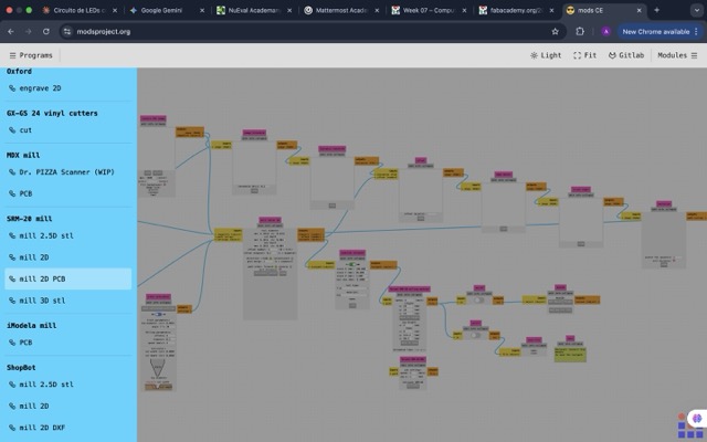
Mods CE
Browser-based toolpath generator. Converts PNG images into CNC instructions.
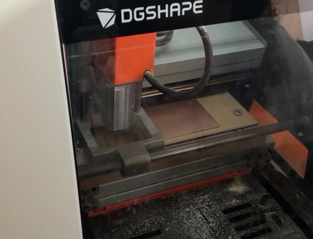
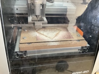
Roland SRM-20
Desktop CNC mill used to cut copper traces on FR1 boards.
File Export
Gerber Export & PNG Conversion
To prepare files for the CNC machine, I exported the design as Gerber files from KiCad's Plot dialog. Then I converted them to high-resolution PNG images using Gerber2png from Fab Lab Kerala — because Mods CE reads PNG, not Gerber.
- 1 KiCad PCB editor → File → Plot
- 2 Select F.Cu and Edge.Cuts layers. Format: Gerber. Click Plot.
- 3 File → Fabrication Outputs → Generate Drill Files. Keep defaults, click Generate.
- 4 Go to gerber2png.fablabkerala.in and upload the Gerber files.
- 5 Download Top Trace PNG and Outline PNG separately.
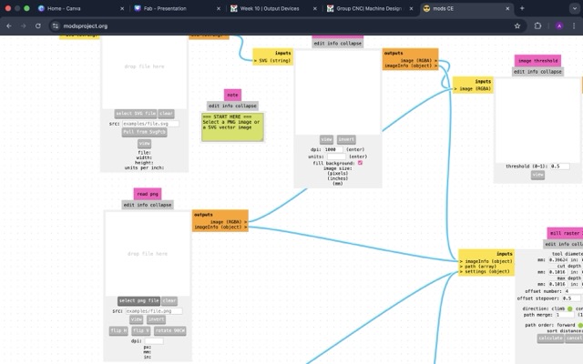
Why PNG and not Gerber directly?
Mods CE reads bitmap images to determine where to mill. A black pixel means "keep copper", a white pixel means "mill away". This is why we convert Gerber → PNG before generating the CNC toolpath. The resolution of the PNG directly affects trace quality.
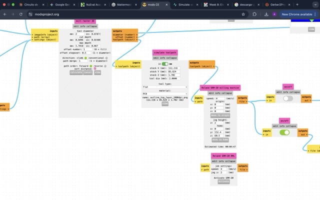
Mods CE Setup
CNC Parameters in Mods CE
Mods CE is the browser-based toolpath generator for the Roland SRM-20. I configured three separate operations with different tools and parameters for traces, drills, and the board outline.
| OPERATION | TOOL SIZE | SPEED | DEPTH |
|---|---|---|---|
| Traces (engraving) | 0.4 mm V-bit | 2 mm/s | 0.1 mm |
| Drills | 0.8 mm flat | 0.5 mm/s | Through board |
| Board outline | 2 mm flat end | 1 mm/s | Through board |
▸ Step by Step: Mods CE Configuration
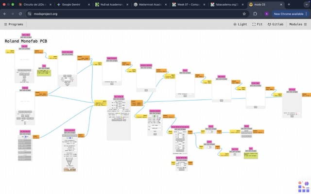
01. Open Mods CE
Go to modsproject.org → Programs → Roland SRM-20 → mill 2D PCB.
02. Load Trace PNG
Click "select png file" and upload the Top Trace image. Set tool diameter to 0.4 mm.
03. Set Parameters
Set speed to 2 mm/s, depth 0.1 mm, origins X/Y to 0. Preview the toolpath simulation.
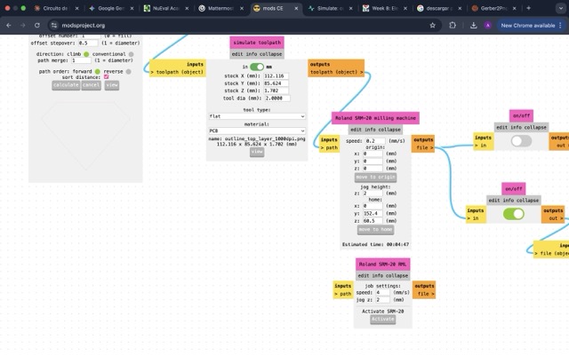
04. Download RML File
Click "calculate" then "save". The .rml file will be sent to the Roland SRM-20 via VPanel.
05. Configure Outline
Repeat the process for Edge.Cuts PNG. Use 2 mm flat tool, set depth to cut all the way through.
PCB Manufacturing
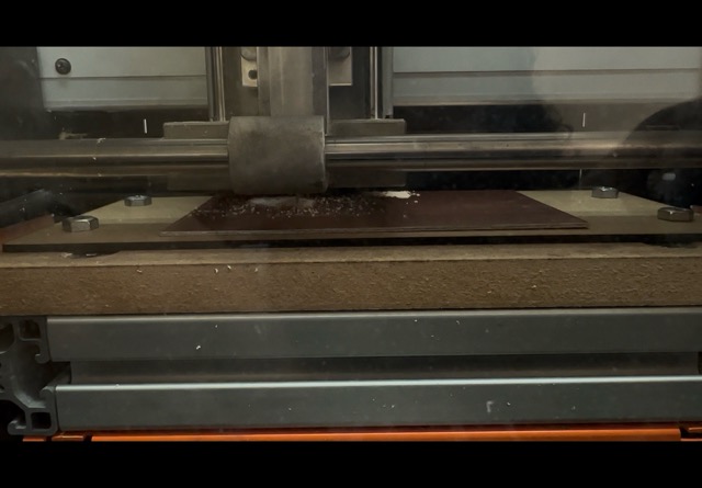
Milling with the Roland SRM-20
The order of operations is critical: drill holes first, then engrave traces, and cut the outline last. This sequence prevents the board from shifting after it's been freed from the base material — which would ruin the alignment.
▸ Step by Step: Roland SRM-20 Setup
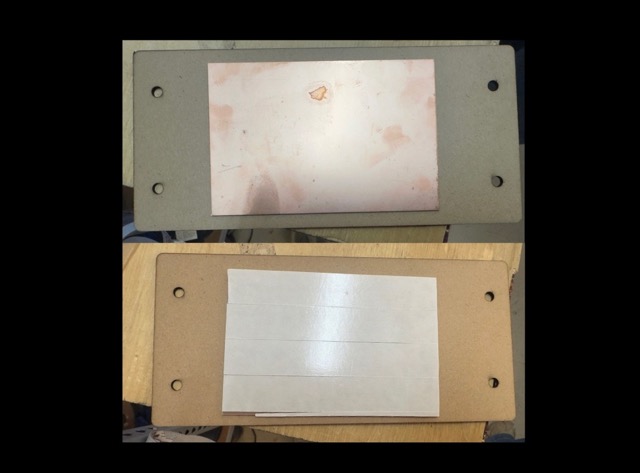
01. Fix the Copper Board
Apply double-sided tape to the back of the FR1 copper board and press firmly onto the MDF sacrificial layer.
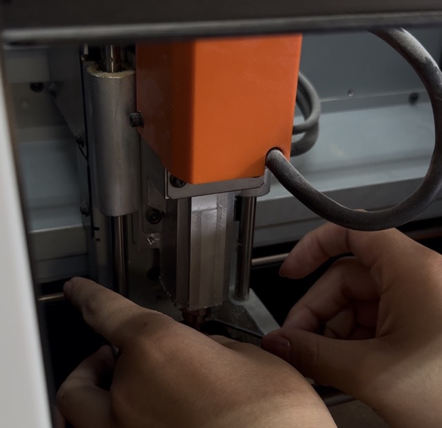
02. Install Drill Bit
Insert the 0.8 mm bit into the collet. Tighten with the wrench — secure but don't overtighten.
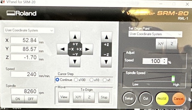
03. Set XY Origin
Use VPanel to jog the spindle to the board corner. Click "Set X/Y Origin" to define the work origin.
04. Calibrate Z Axis
Slowly lower the tool until it barely touches the copper surface. Set Z origin. Raise tool before running the file.
05. Mill Traces
Switch to 0.4 mm V-bit, re-zero Z, and run the trace toolpath. Monitor the machine at all times.
06. Cut Board Outline
Switch to 2 mm flat end mill, re-zero Z, and run the outline file. The board is free after this step.
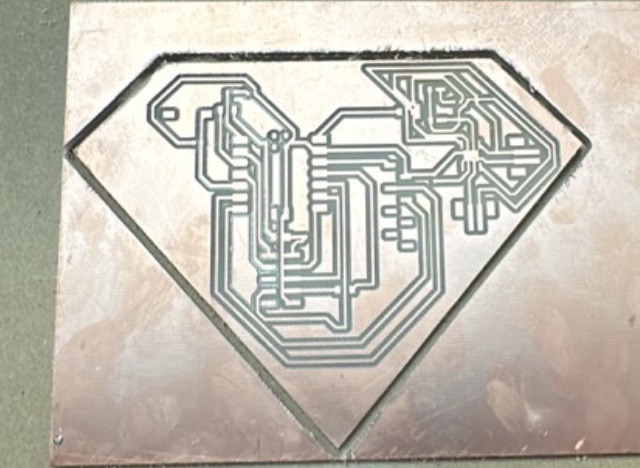
Results — Milled PCB
Component Soldering
Soldering Process
I recommend soldering from the smallest components to the largest to avoid blocking your working area. SMD resistors and LEDs go first, then connectors, and the microcontroller last.
I applied soldering paste to the pads with a toothpick before using the iron and solder wire. My iron temperature was set to 270°C — slightly below the typical 290–300°C range since it was my first time soldering SMD components. Better to go slow.
Tip: Continuity Test Before Powering Up
After soldering all components, use a multimeter in continuity mode (the beep symbol). Touch one probe to a trace and the other to an adjacent trace — if it beeps, you have an accidental short circuit to fix before connecting USB. This step saves a lot of debugging time and protects your microcontroller.
Board Testing
Programming with Arduino IDE
I connected the finished board to my laptop via USB-C. To program it, I added the RP2040 board package to Arduino IDE and ran two simple tests to verify the LEDs and button worked correctly.
- 1 Open Arduino IDE → File → Preferences
- 2 Paste this URL in "Additional Boards Manager URLs":
https://github.com/earlephilhower/arduino-pico/releases/download/global/package_rp2040_index.json
- 3 Open Board Manager → Search "Raspberry Pi Pico/RP2040" → Install
- 4 Tools → Board → XIAO RP2040
- 5 Select the correct port and upload your sketch
▸ Test 1: Button Controls LEDs
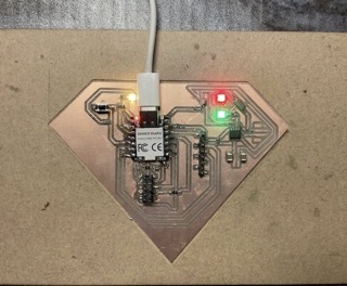
Button press → LEDs on
Pressing the button turns all LEDs on. Releasing turns them off. Validates the pull-up resistor and button wiring.
// Test 2: Button → LEDs
const int button = D3;
const int led1 = D0;
const int led2 = D1;
const int led3 = D2;

void setup() {
  pinMode(button, INPUT_PULLUP);
  pinMode(led1, OUTPUT);
  pinMode(led2, OUTPUT);
  pinMode(led3, OUTPUT);
}

void loop() {
  int state = digitalRead(button);

  if (state == LOW) {
    digitalWrite(led1, HIGH);
    digitalWrite(led2, HIGH);
    digitalWrite(led3, HIGH);
  } else {
    digitalWrite(led1, LOW);
    digitalWrite(led2, LOW);
    digitalWrite(led3, LOW);
  }
}
Downloadables
Here you can find the KiCad project, Gerber files, PNG images, and Arduino sketches from this week.
⬇ Download Project Files