Main Software
KiCad
Fab Academy 2026
Designing, fabricating and integrating the electronic system for a CNC machine using custom PCBs and ESP32-based control.
KiCad
ESP32, motor drivers, AMS1117 regulators, electric terminal block and pin headers.
Design and organize the electronic system for the CNC machine.
During this assignment, our team designed and built a CNC machine that integrates mechanical structure, electronic control and automation.
The machine was first tested manually to validate the movement system and later integrated with electronics and programming for automation.
This project helped us better understand how mechanical, electronic and software systems interact inside a complete machine workflow.
For this week, I was mainly responsible for designing and organizing the electronics implemented in the CNC machine.
Initially, I designed a single PCB that combined both the logic and power sections into one board.
However, after routing and organizing the components, I realized that the design became too crowded and difficult to manage.
Because of this, I decided to separate the electronics into two independent PCBs.
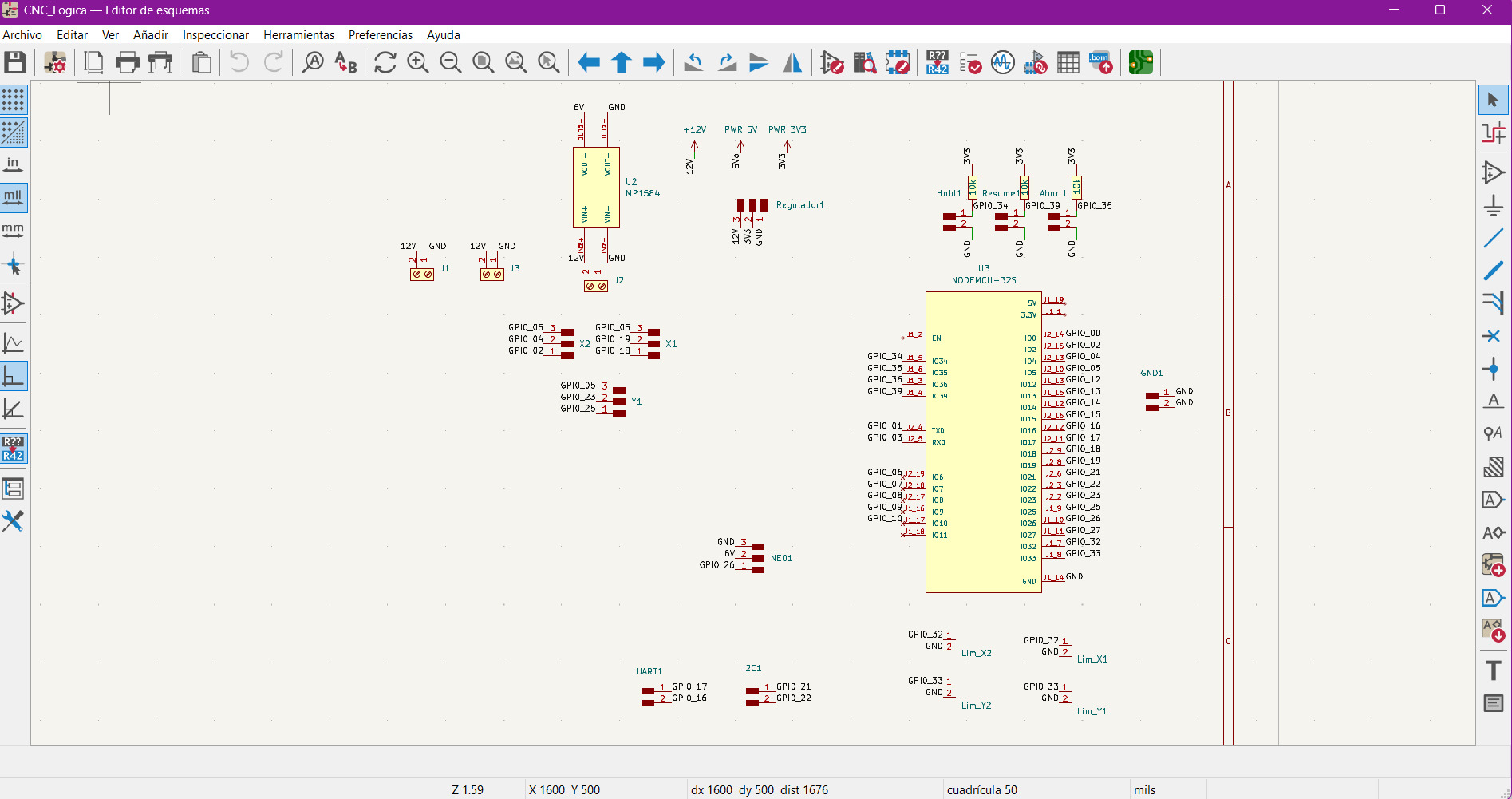
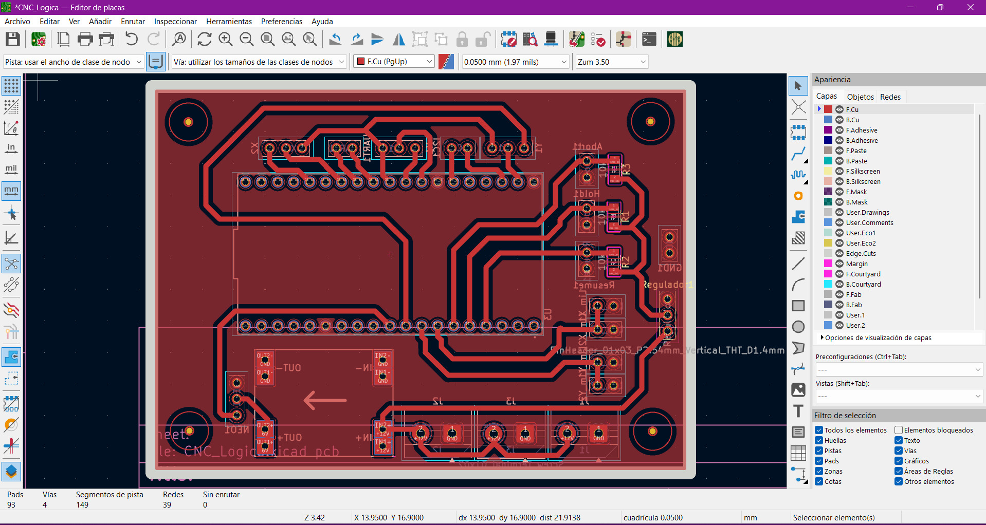
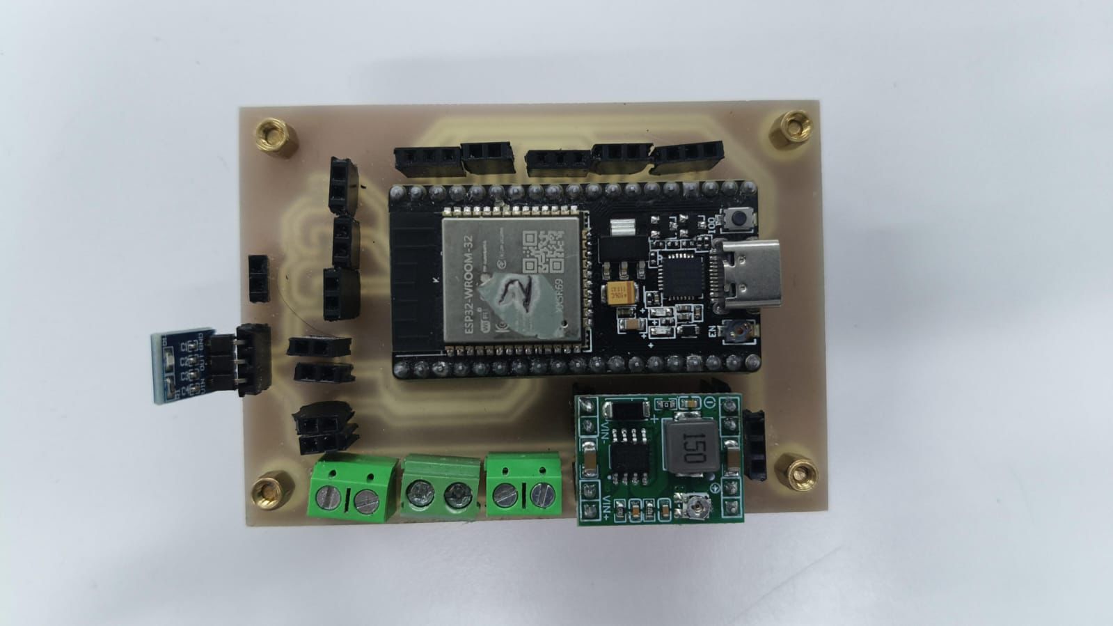
The first PCB was dedicated only to the logic section of the machine, first it was intended for a completly different machine, but then we decided to change the goal. All this is explained in the group assignment, so I will not go into details here.
This board included the ESP32, pin outputs, voltage regulation and terminal blocks for easier external connections.
Separating the logic circuitry from the power stage made the PCB much cleaner and easier to organize inside KiCad.
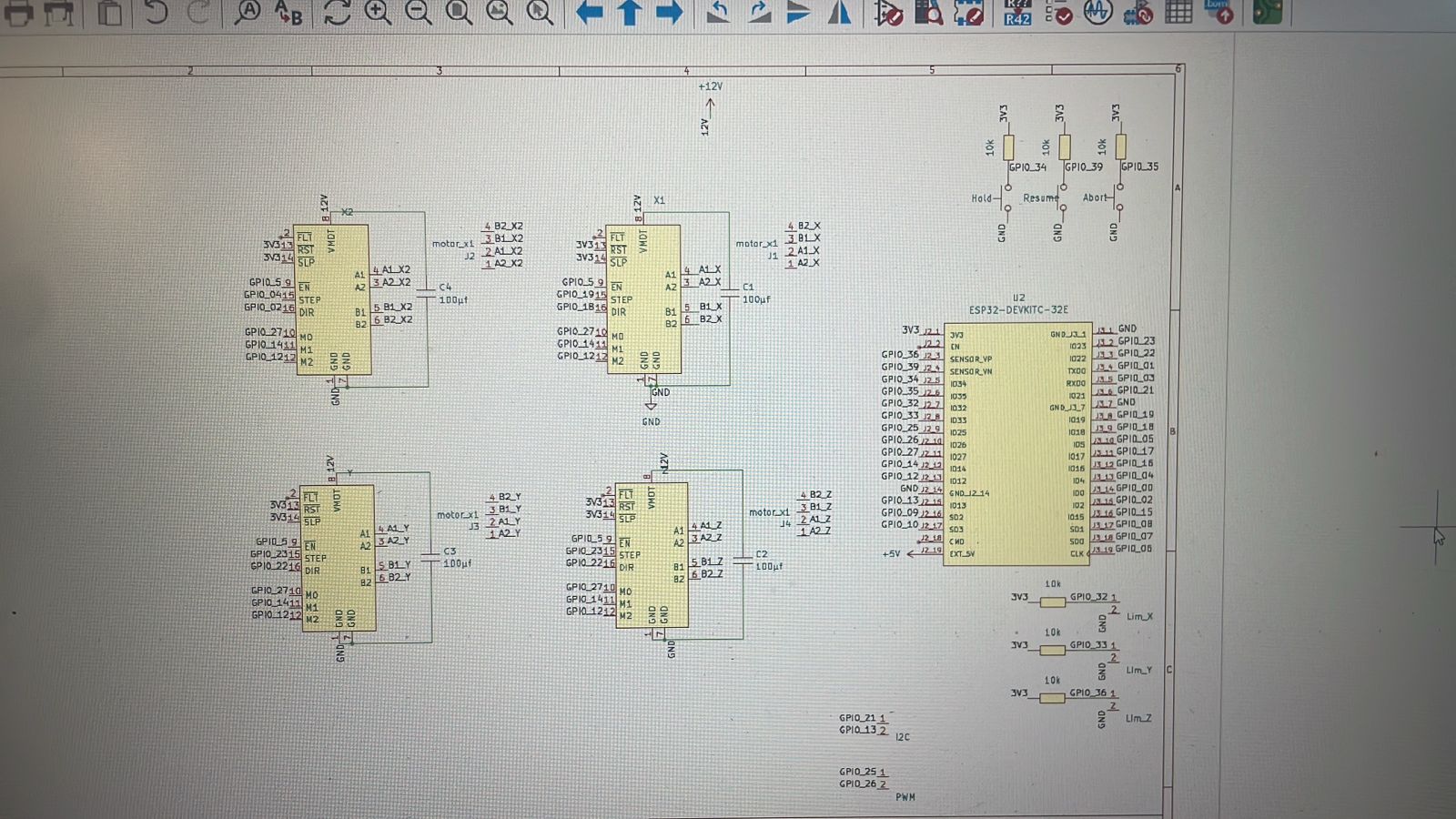
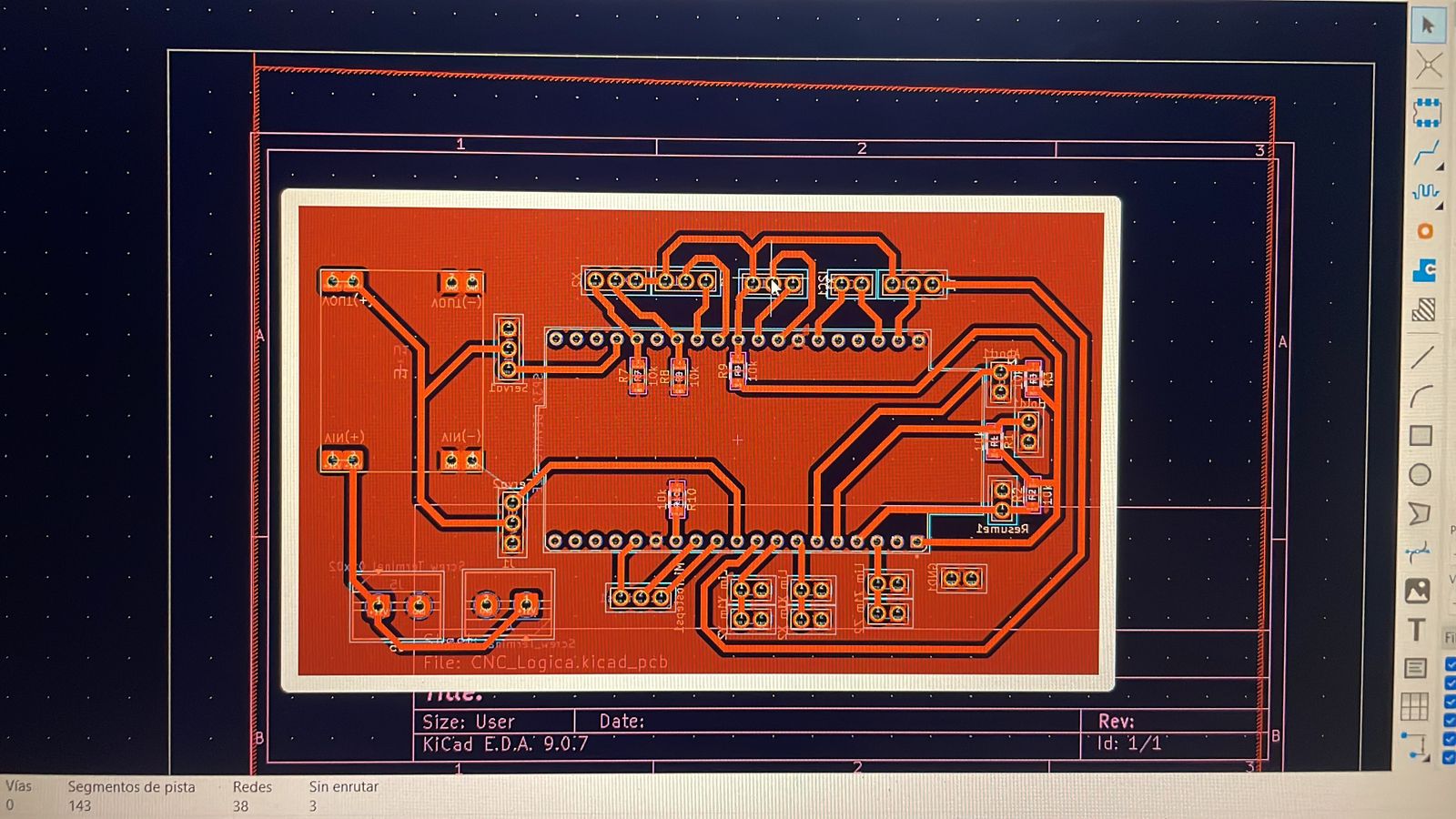
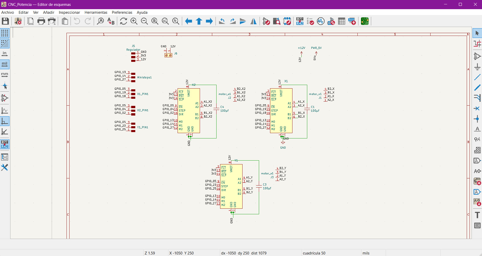
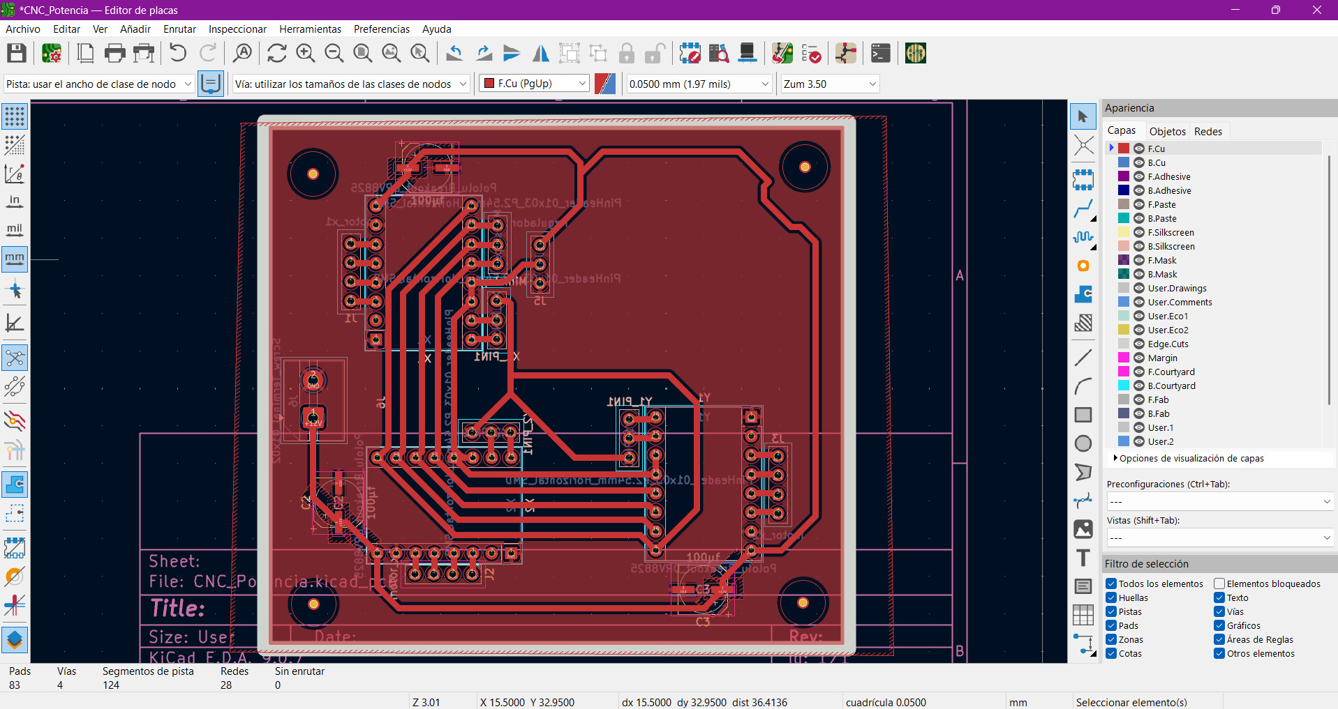
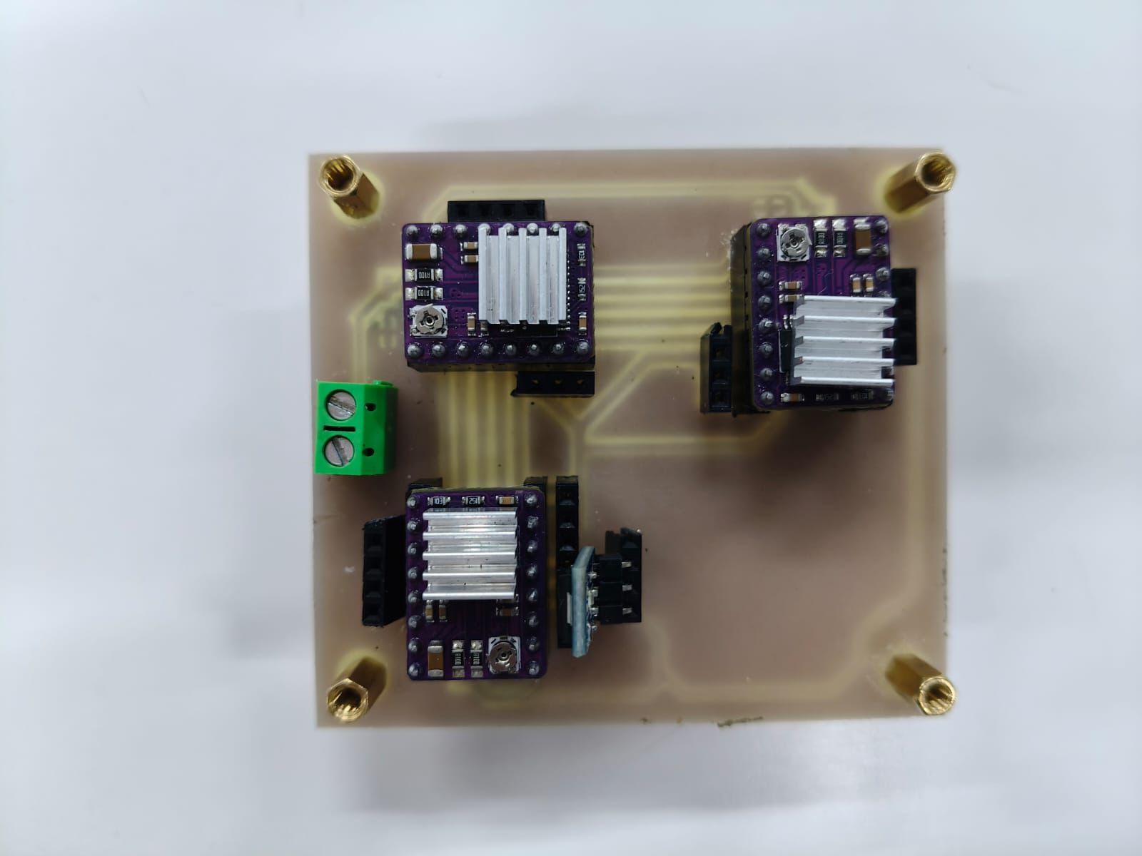
The second PCB was designed specifically for the power stage of the CNC system.
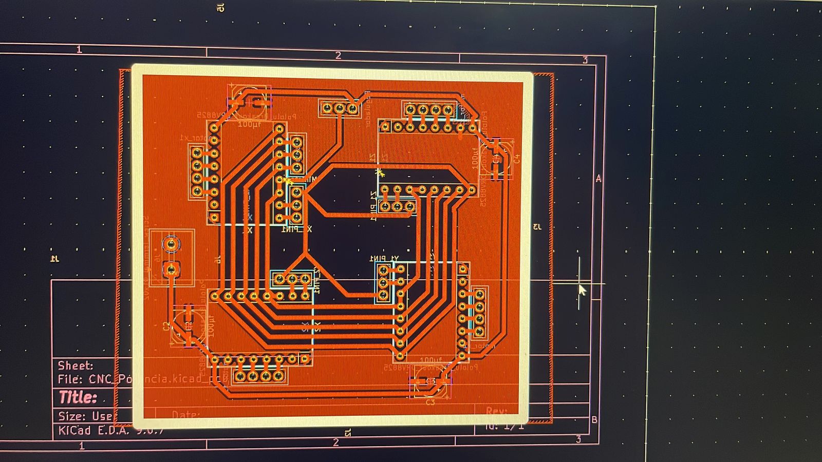
This board included the motor drivers, an AMS1117 voltage regulator module and multiple pin headers for external connections.
Dividing the electronics into two boards simplified both the routing process and future debugging tasks.
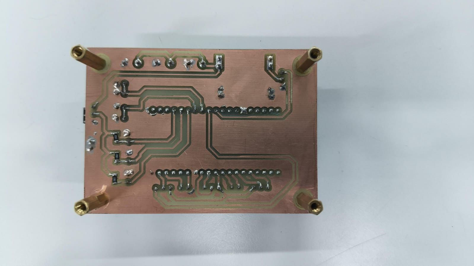
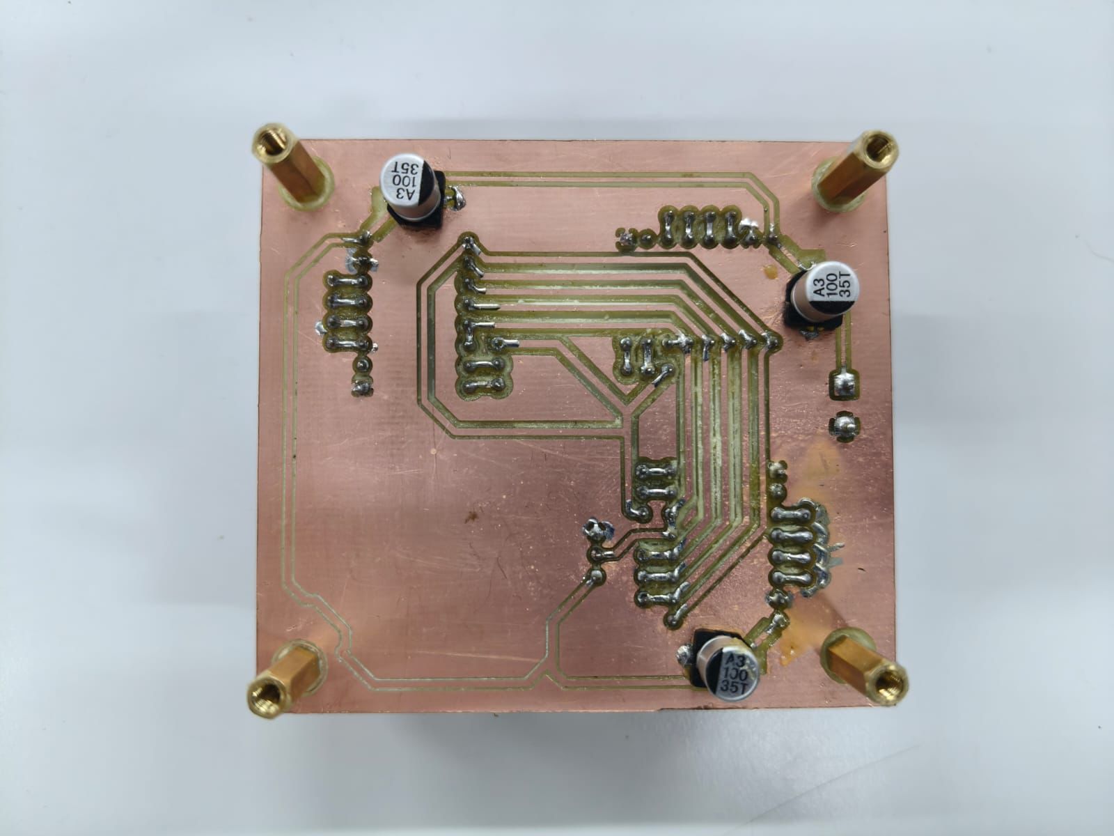
After organizing the PCB layouts, I soldered all the components and tested each board individually.
Testing each PCB separately made it easier to identify possible issues and confirm that the boards were working correctly before integrating them into the CNC machine.
Separating logic and power systems greatly improves PCB organization and debugging.
Machine design requires coordination between electronics, mechanics and programming.
Testing each subsystem independently reduces integration problems later.