12. Mechanical, Machine Design Group Assignement
How it started...
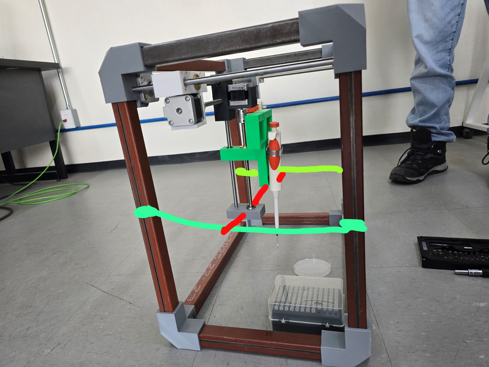
So, for this assignement our teacher Aristarco proposed some ideas and we decided to give one a shot: an automated pipette that draws with microliter drops. He shared the following references:
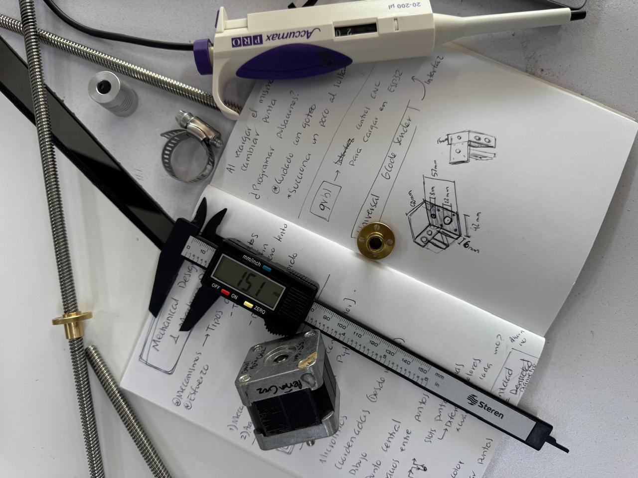
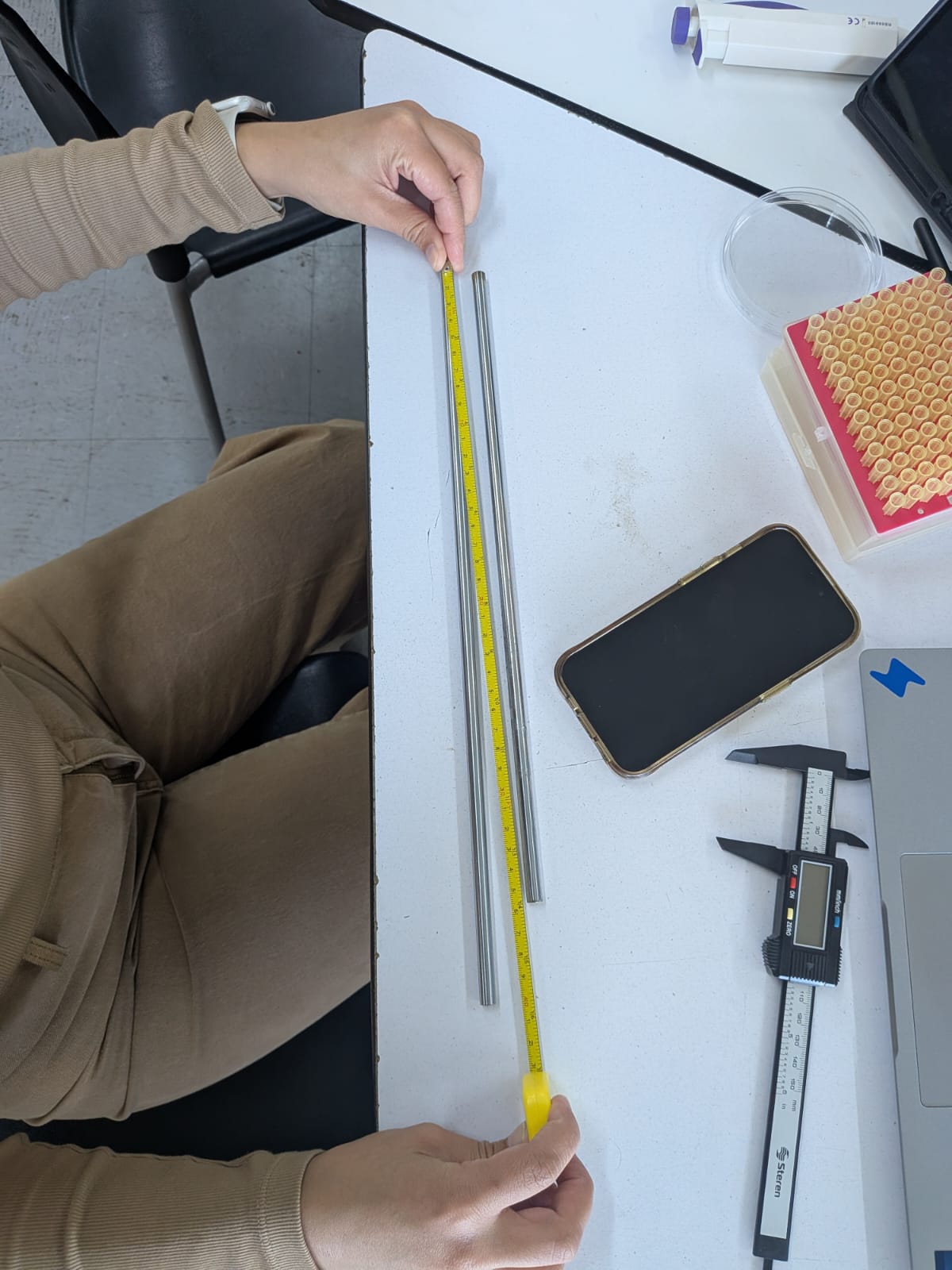
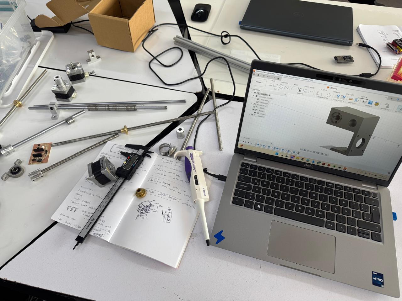
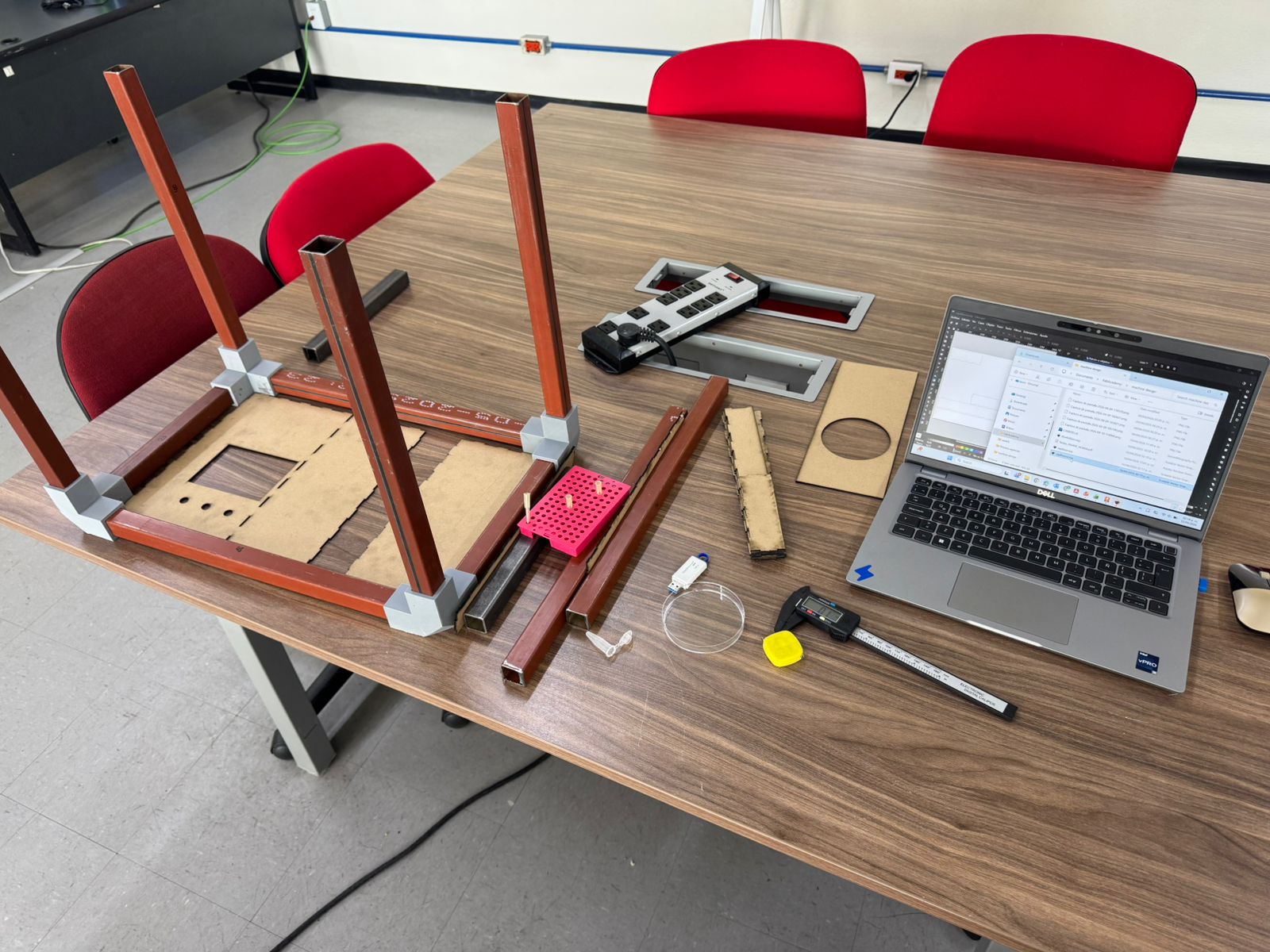
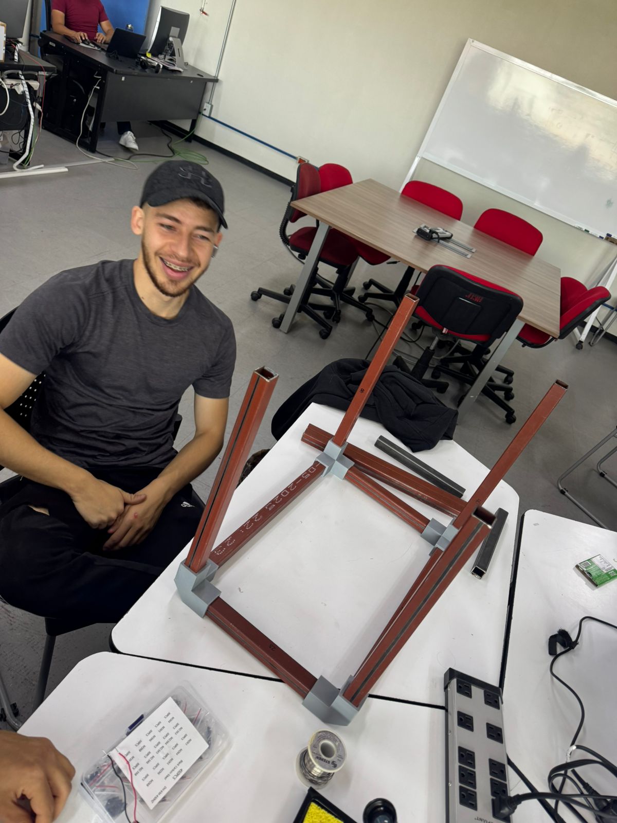
With this in mind, we gathered our materials measured them and started designing or machine.
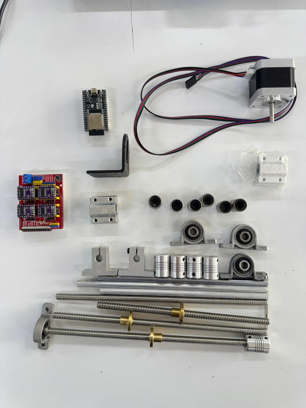
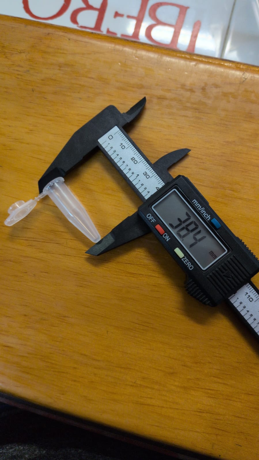

Our inventory:
| Machine part | Material | Description | Quantity |
|---|---|---|---|
| Structure | Aluminum bar | Various measurements | 12 |
| Structure | Vertex unions | Bar union only. *3D print | 4 |
| Structure | Vertex unions | With motor and bar holder. *3D print | 2 |
| Structure | Vertex unions | With bearing and bar holder. *3D print | 2 |
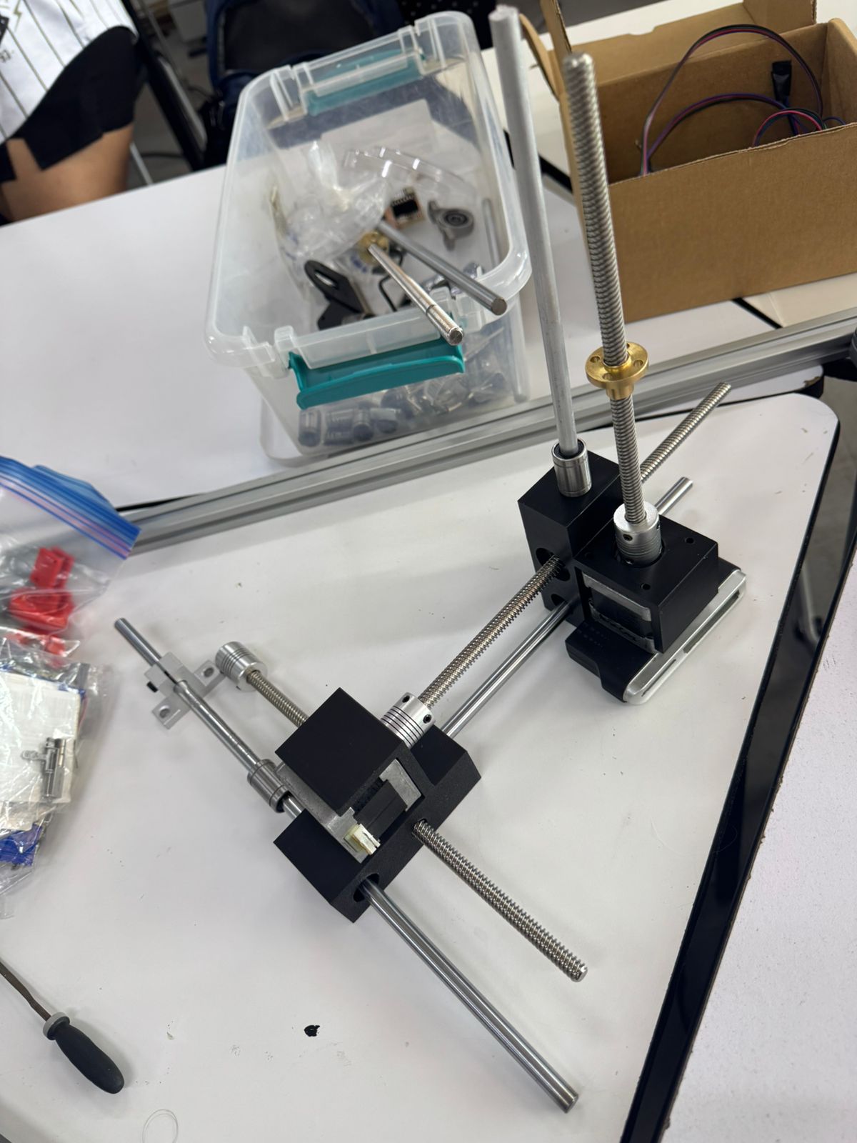
| Y axis | Endless screw | 8mm and 300mm | 2 |
| Y axis | Aluminum bar | 8mm and 300mm | 2 |
| Y axis | Bearing | 8mm inner diameter | 2 |
| Y axis | Couplet | 8mm and 5mm | 2 |
| Y axis | Endless screw gear | 8mm | 2 |
| Y axis | Cilindrical bearing | 8mm | 2 |
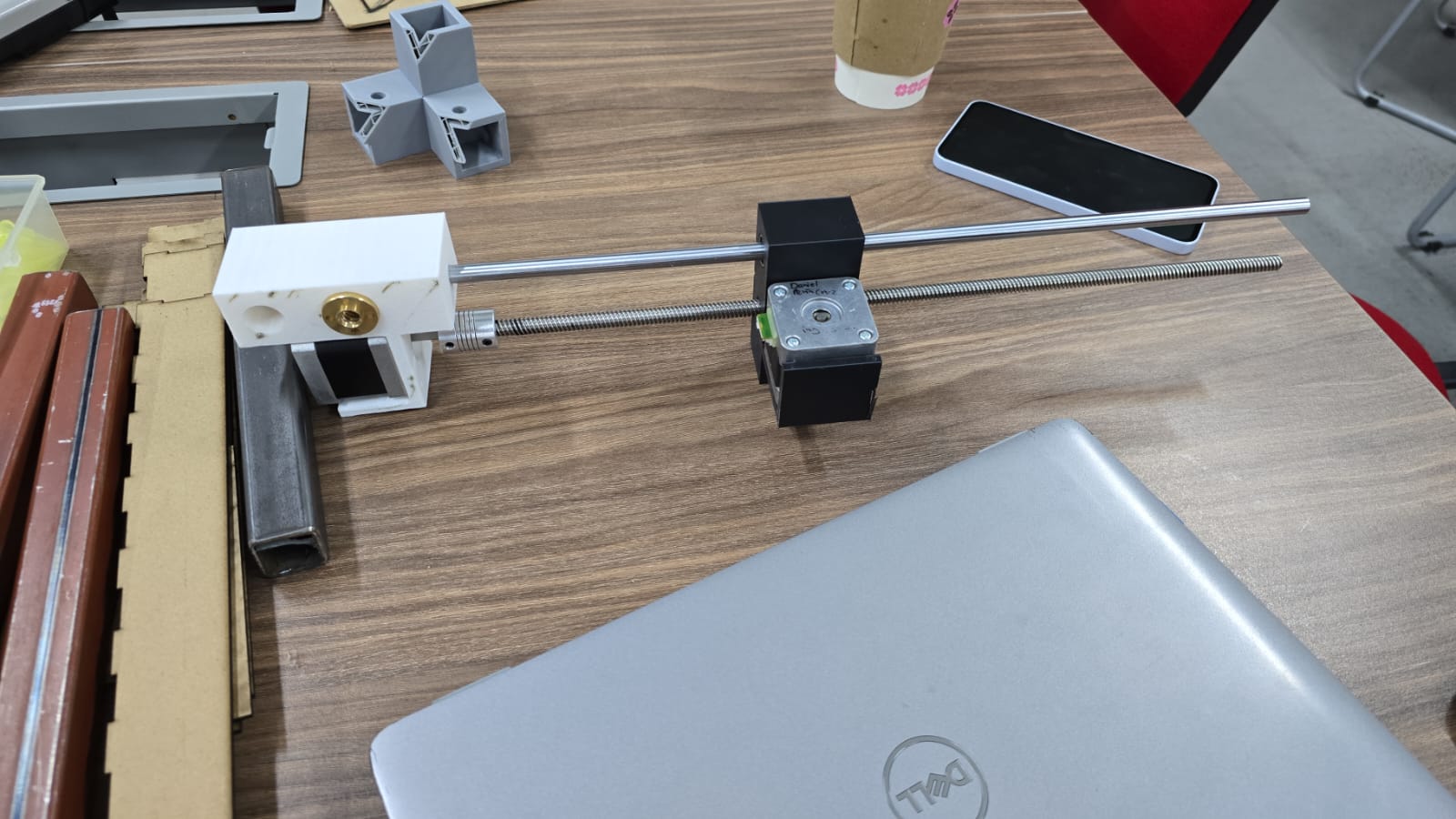
| X axis | Endless screw | 8mm and 400mm | 1 |
| X axis | Aluminum bar | 8mm and 400mm | 1 |
| X axis | Endless screw gear | 8mm | 1 |
| X axis | Motor car | 3D designed and printed | 1 |
| X axis | Stop car | 3D designed and printed | 1 |
| X axis | Bearing | 8mm inner | 1 |
| X axis | Couplet | 8mm and 5mm | 1 |
| X axis | Cilindrical bearing | 8mm | 1 |
| Z axis | Motor car | 3D designed and printed | 1 |
| Z axis | Endless screw | 8mm and 200mm | 1 |
| Z axis | Endless screw gear | 8mm | 1 |
| Z axis | Aluminum bar | 8mm and 200mm | 1 |
| Z axis | Bearing | 8mm inner | 1 |
| Z axis | Stop | 3D designed and printed | 1 | Z axis | Couplet | 8mm and 5mm | 1 | Z axis | Pipette | microliters | 1 | Z axis | Clamps | For pipette | 2 |
| Base | Acrilic Boxes | 3mm acrilic, various box sizes. *Laser cut | 2 |
| Base | Pipette serynges box. | Given by instructors | 1 |
| Base | Agar gel circular container | Given by instructors | 1 |
| Base | Sample containers | Given by instructors | 3 |
| Electronics | Microcontroler | ESP32 D | 1 |
| Electronics | Stepper motor | Nema 17 | 4 |
| Electronics | Stepper motor driver | DRV8825 | 4 |
| Electronics | H bridge | 4 | |
| Electronics | Copper sheets | 2 | |
| Electronics | Push buttons | 3 | |
| Electronics | Power source | 15V and 5amp | 1 |
| Electronics | Data, power and connection cables | Many |
3D printing
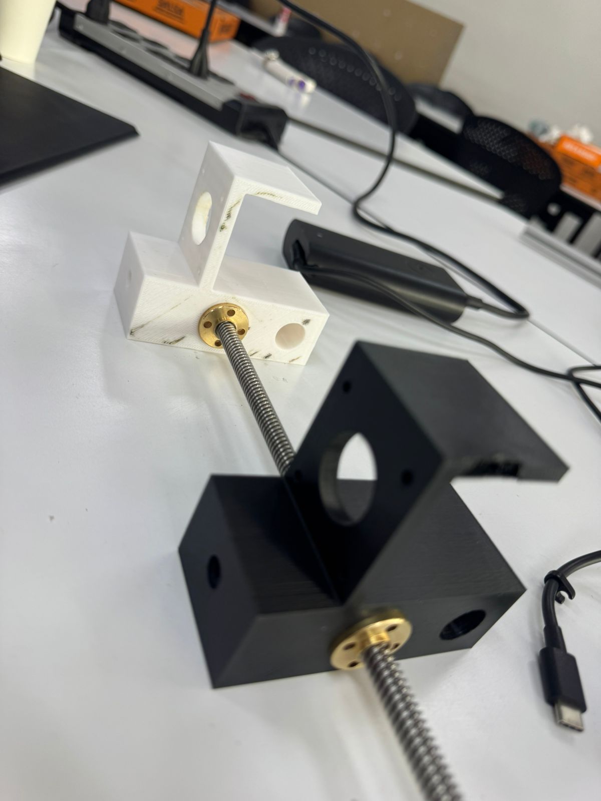
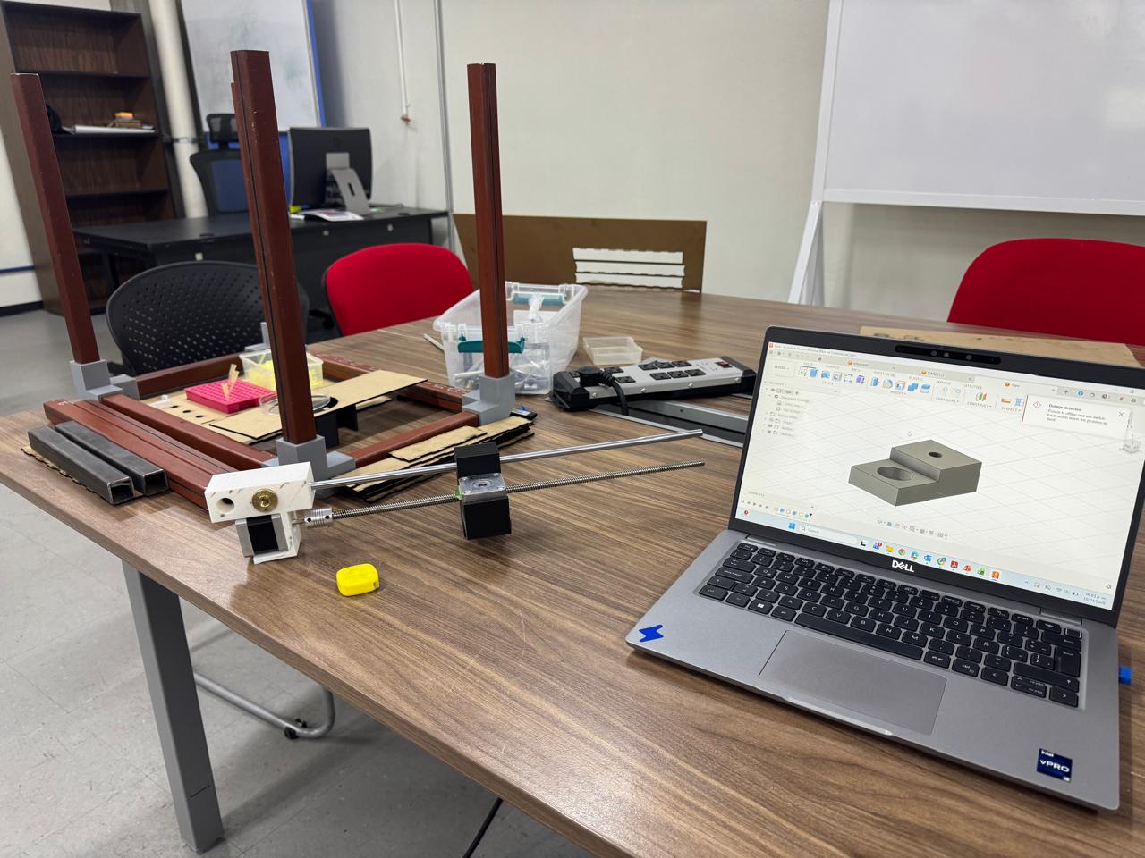
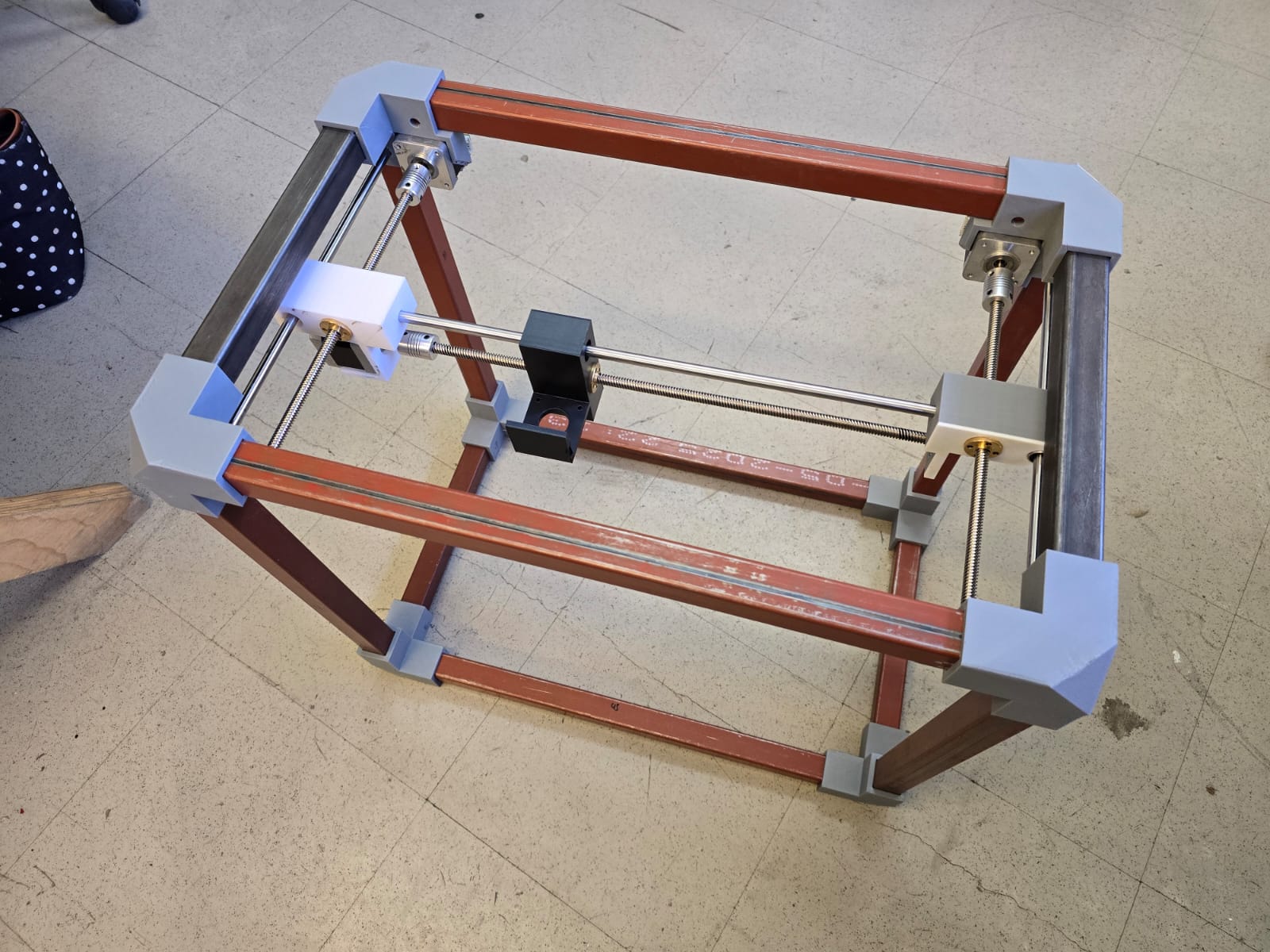
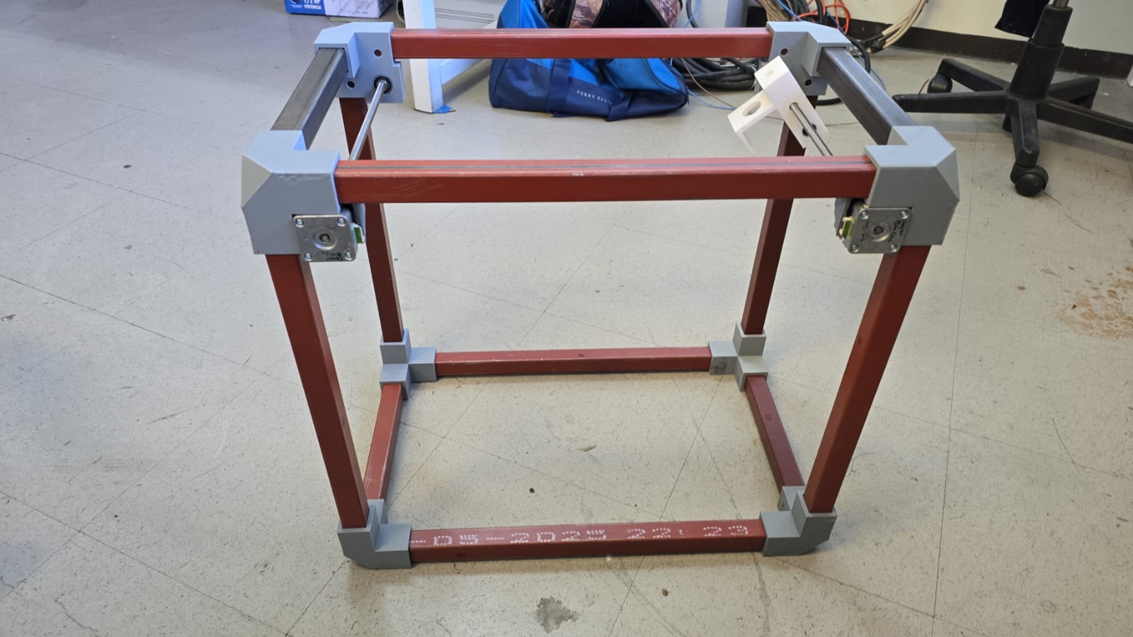
With all materials on the table and measurements noted, we created a 3D model of what we thought the machine would look like. Along with the existing materials, we started designing the missing pieces we would have to print:
- Vertex unions
- Axis cars
- Vertex with motor holders
- Vertex with bearings
- Stoper X axis
- Stoper Z axis
- Pipette holder

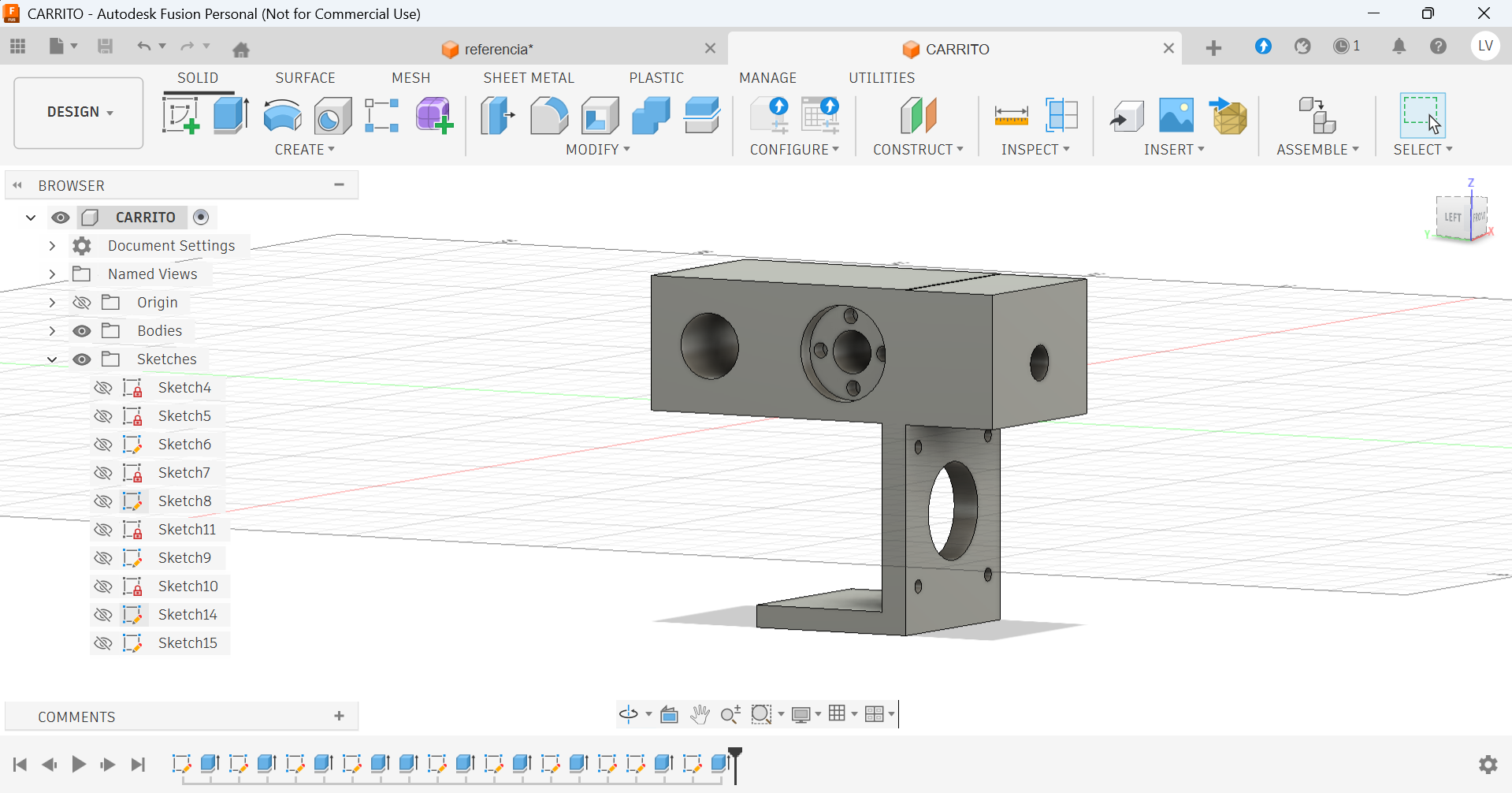
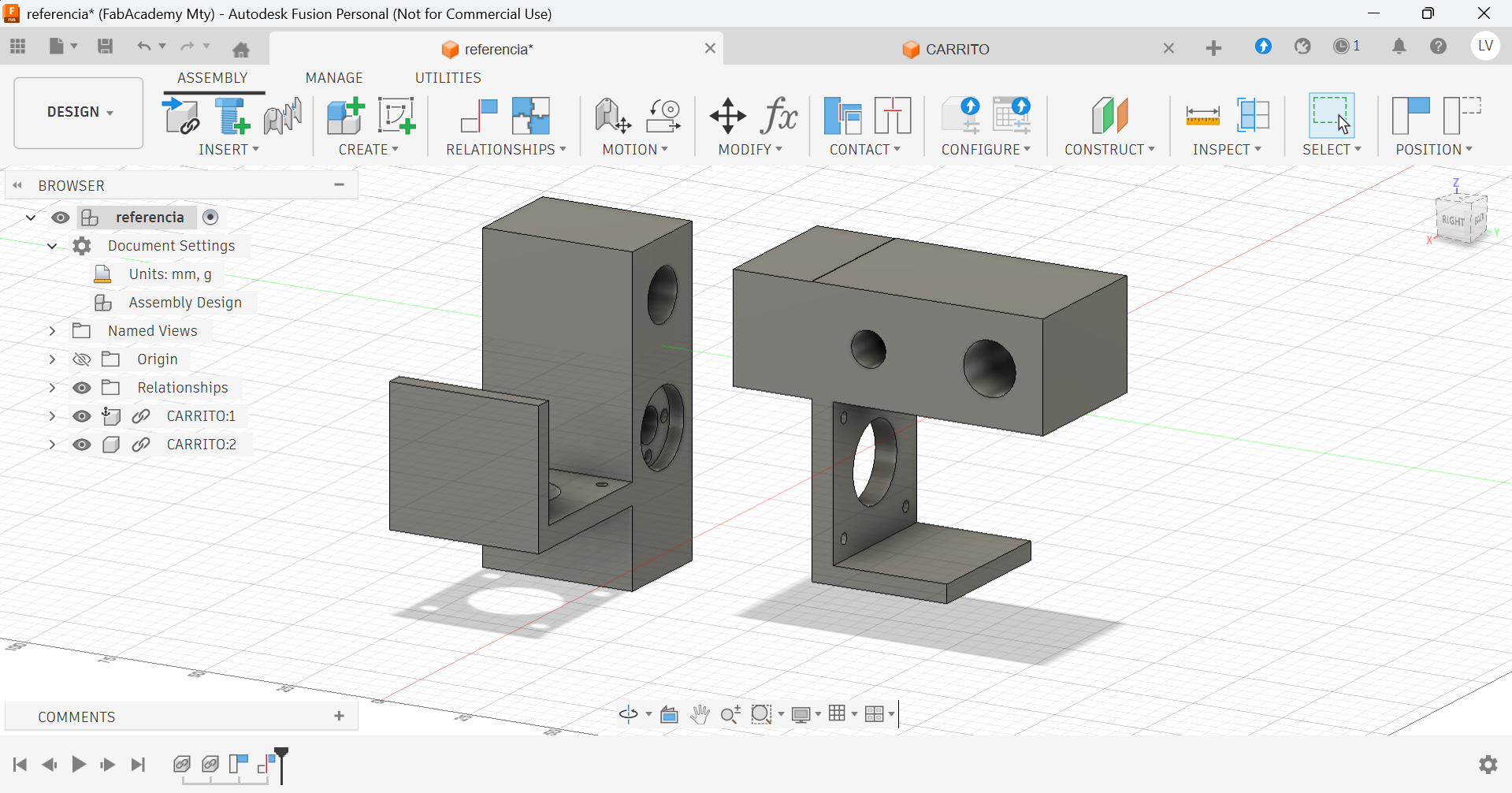
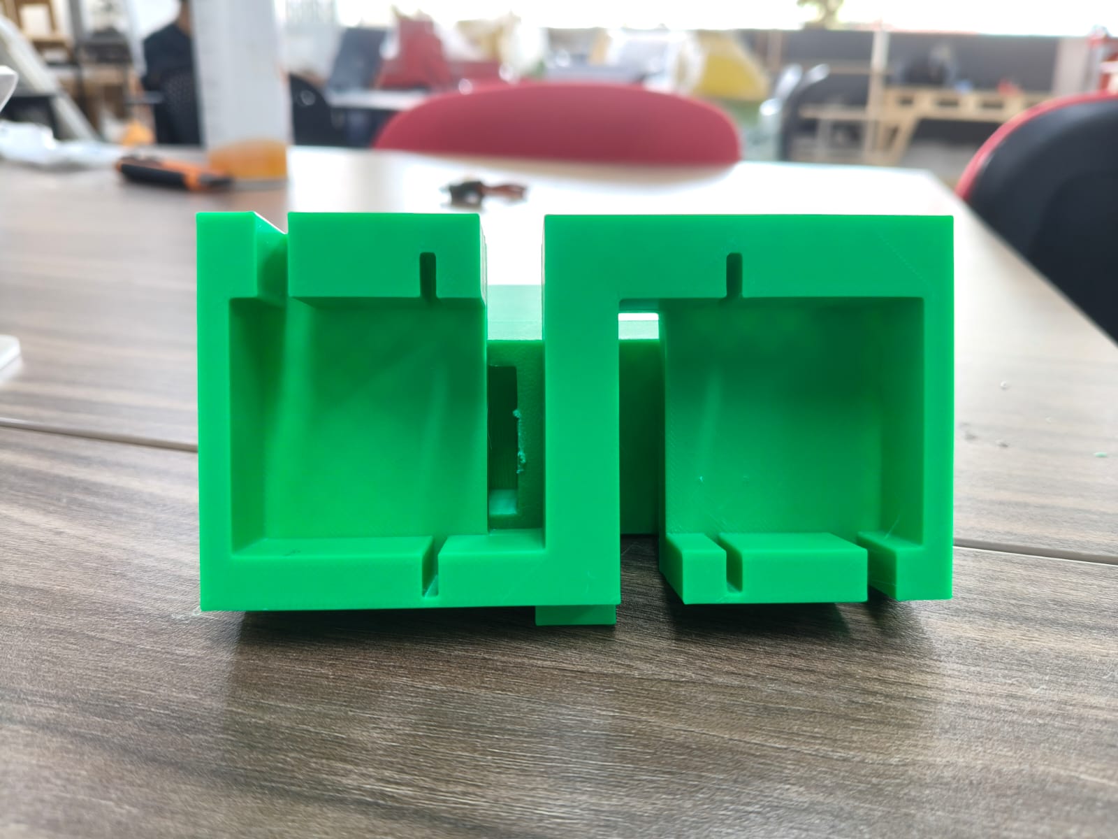
*Some pieces had to be printed, tested, modified and printed again. (Like the motor cars)
Laser cutting
We also had to design a base for the pipette syringes, samples, agar gel canvas and trash. We planned on producing it on acrilic, but teste with MDF first:
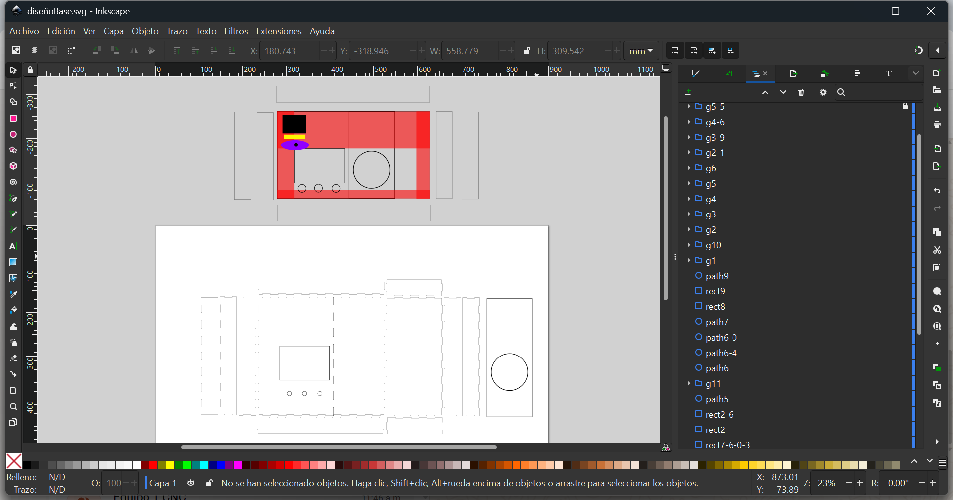
*A very important consideration for designing this base was the working area. The mechanical design and structure had to be definitive to see where the pipette would really be able to move, and therefore, where we could place the things it would interact with.
To make sure the wroking area, sizes and holes were correct, we cut out a test on MDF with the laser cutter:
We noticed some mistakes and felt glad it was only a test. This helped us gather information and allowed us to see how important it was to test the mechanics and electronics before moving forward.
Electronics
To work faster, we decided to divide and conqueer: writing code, testing hardware and designing our PCB was all done at the same time by different members of the team.
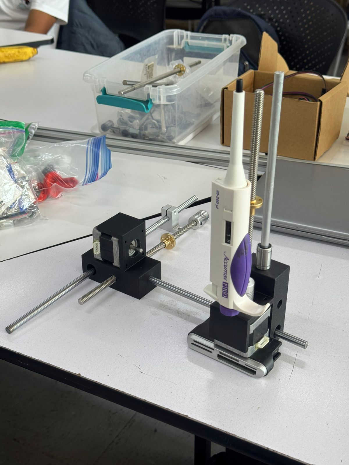
Hardware testing
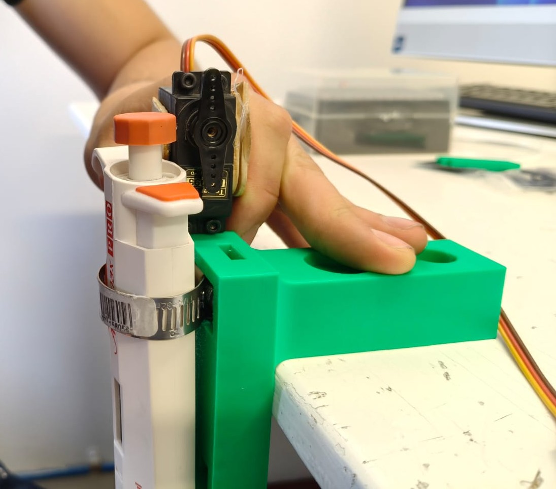
This piston actuator was our first option for pushing our pipette's buttons. This action would absorb or release the liquid to create our points:
Test code 1
Test code 2
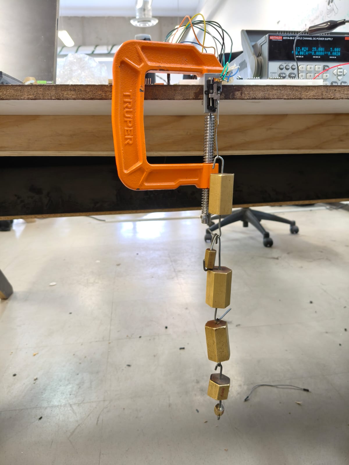
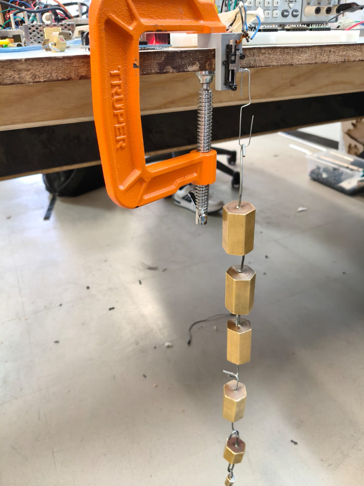
After realizing the piston actuator did not have enough strength to push the pipette's buttons, we tried and succeded with a servo motor using this code:
Each stepper motor was also tested using this code:
*We also added start, pause and resume buttons to control the sistem.
PCB design and production
Both schematic and PCB were designed in KiCad with all components:
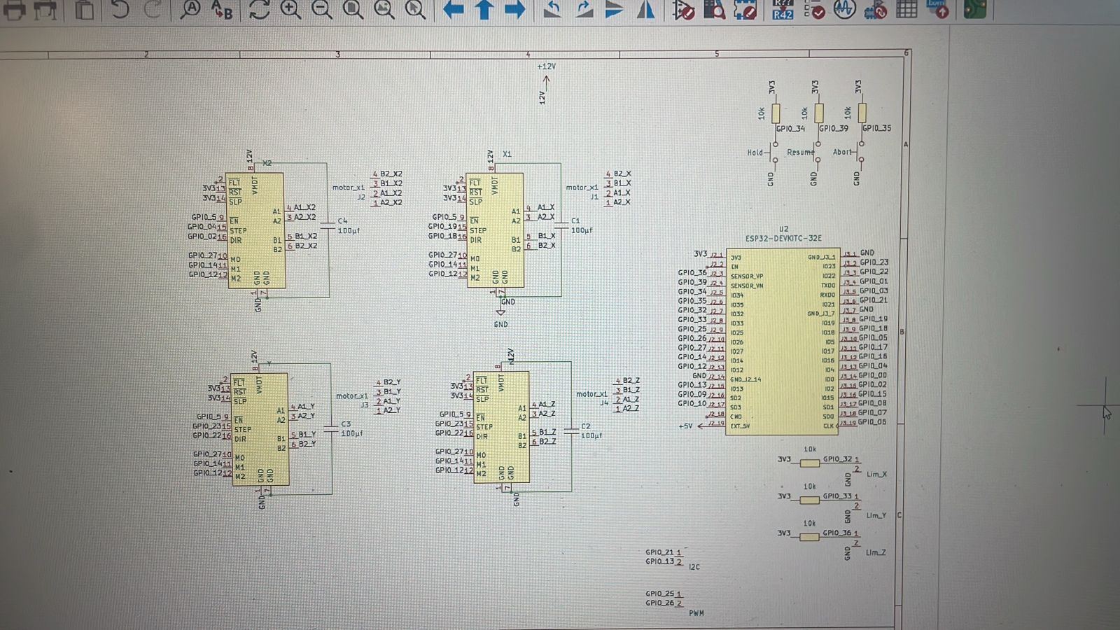
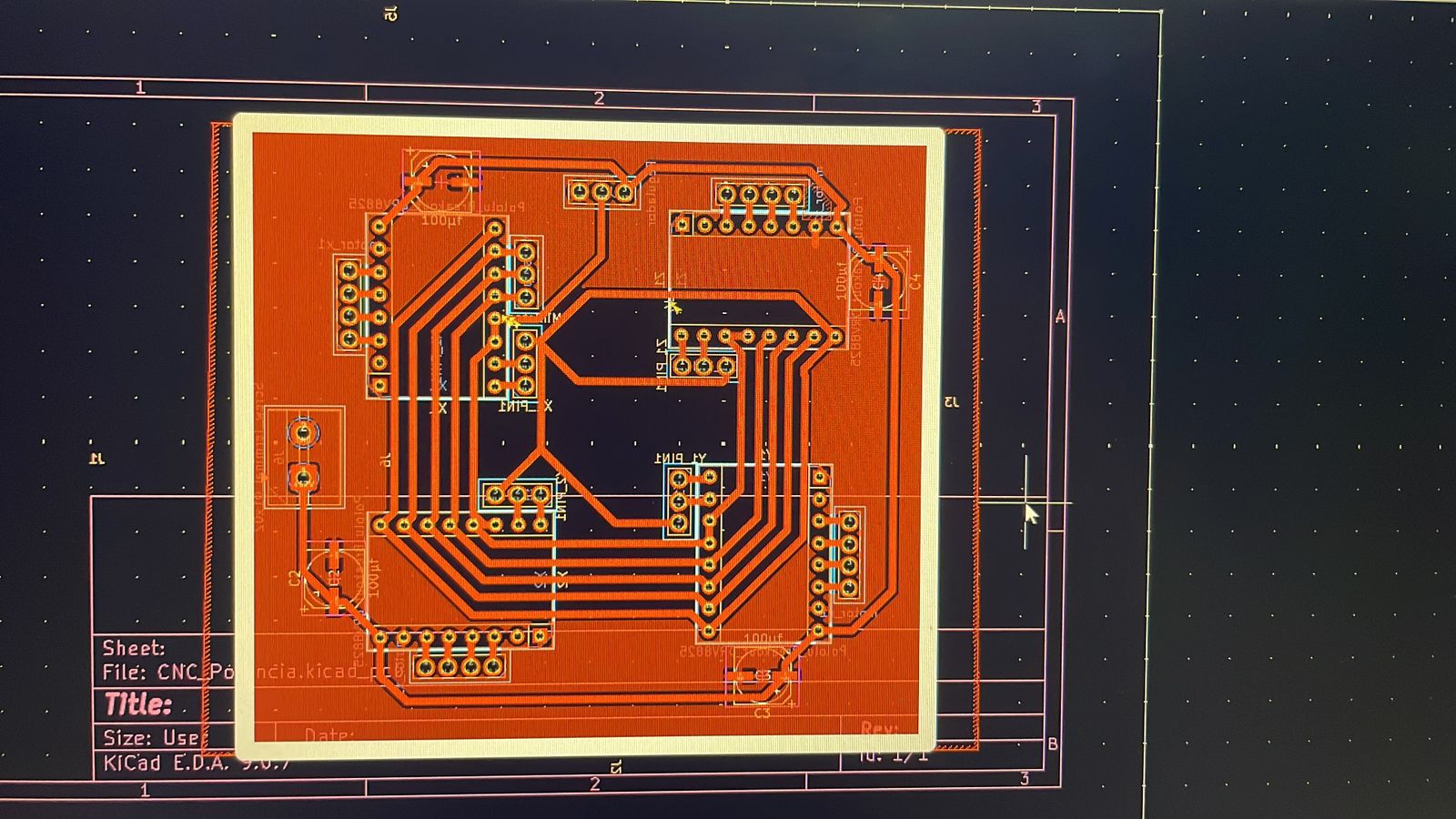
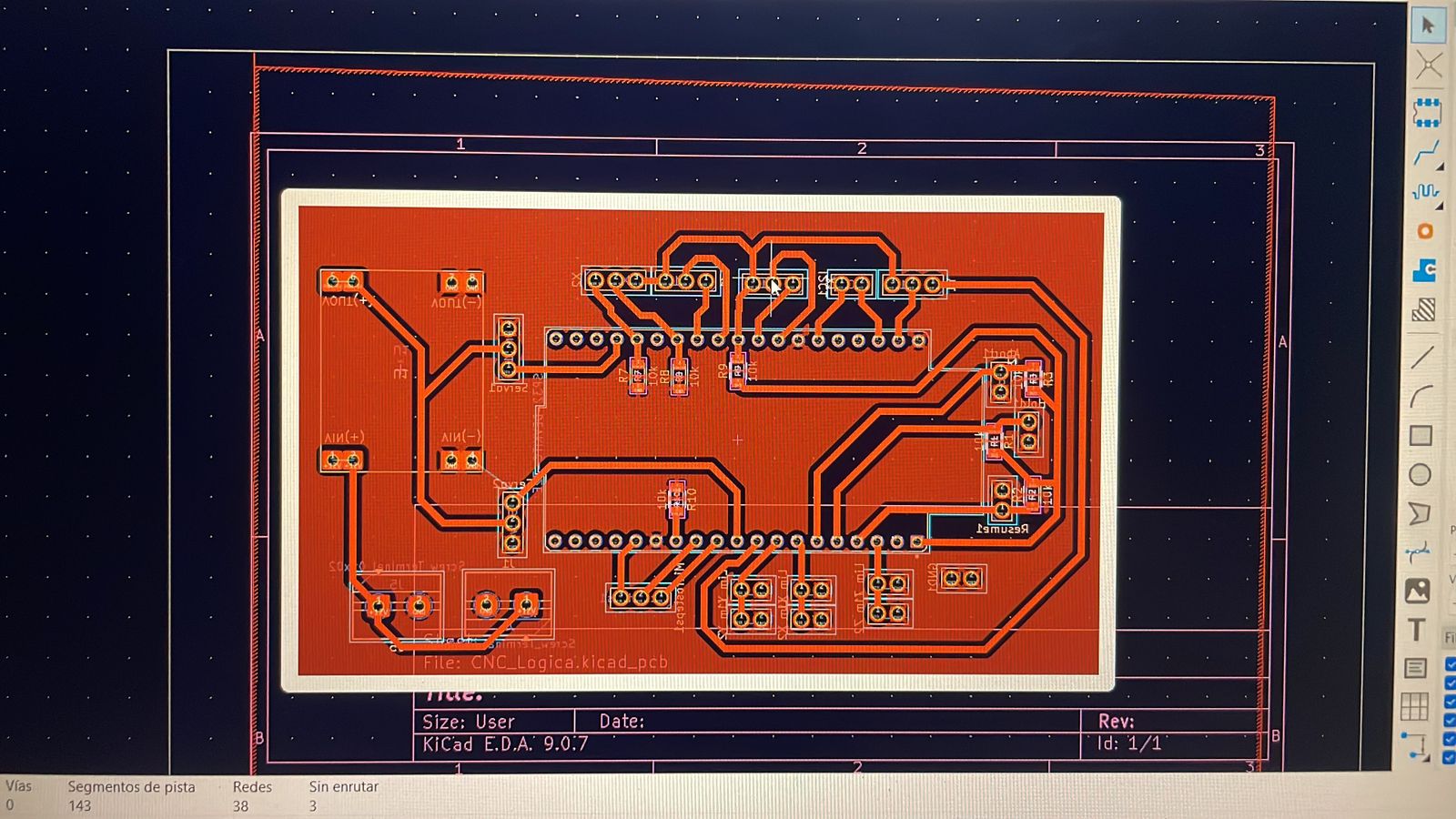
The processed result looked like this:
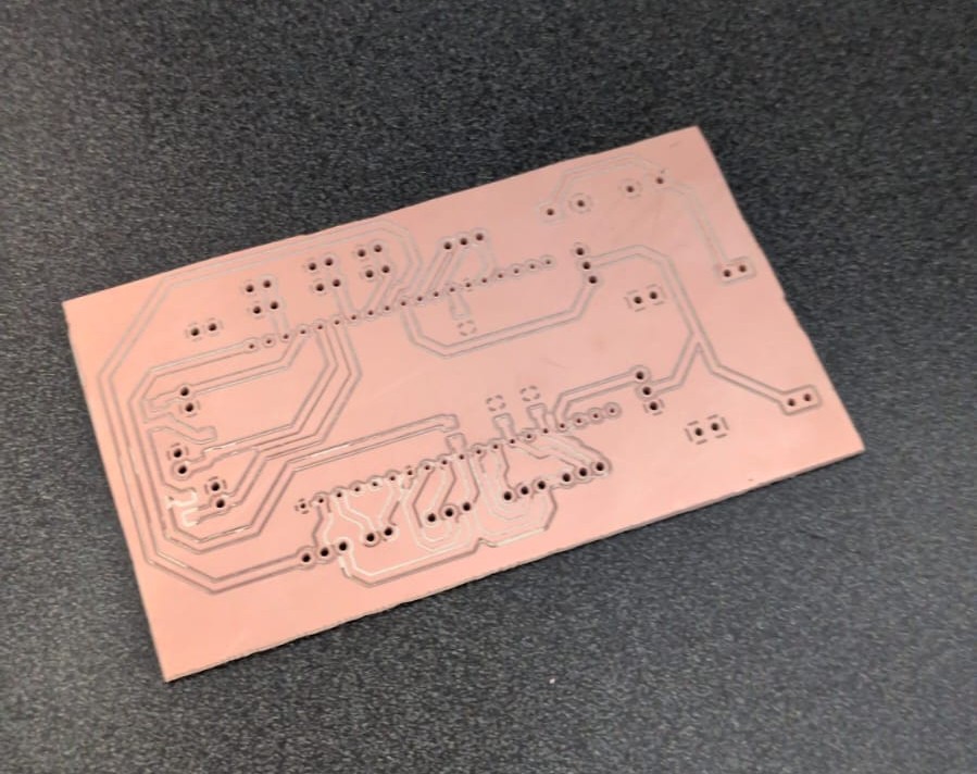
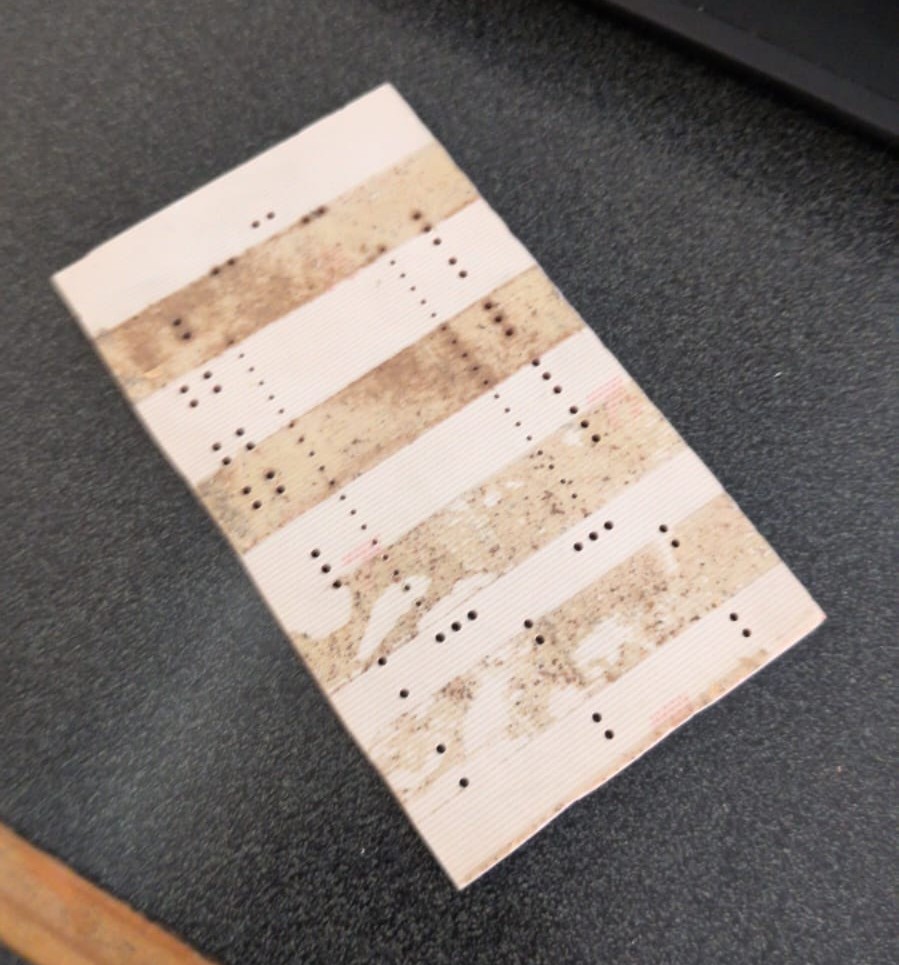
*All documents can be found here.
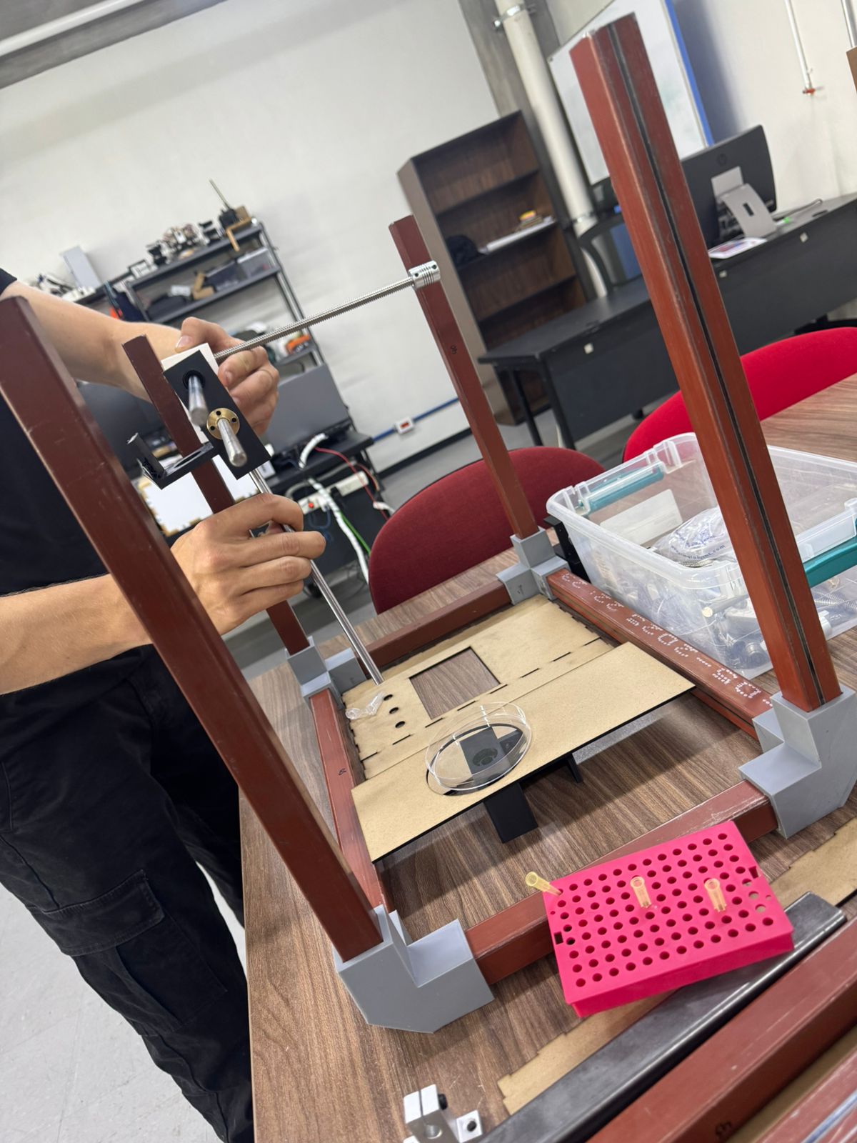
Assembly
After testing all individual parts and components, it was time to put this machine together.
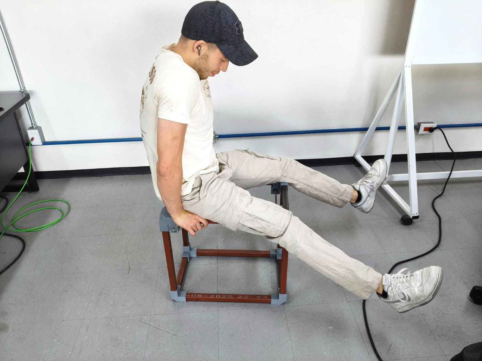
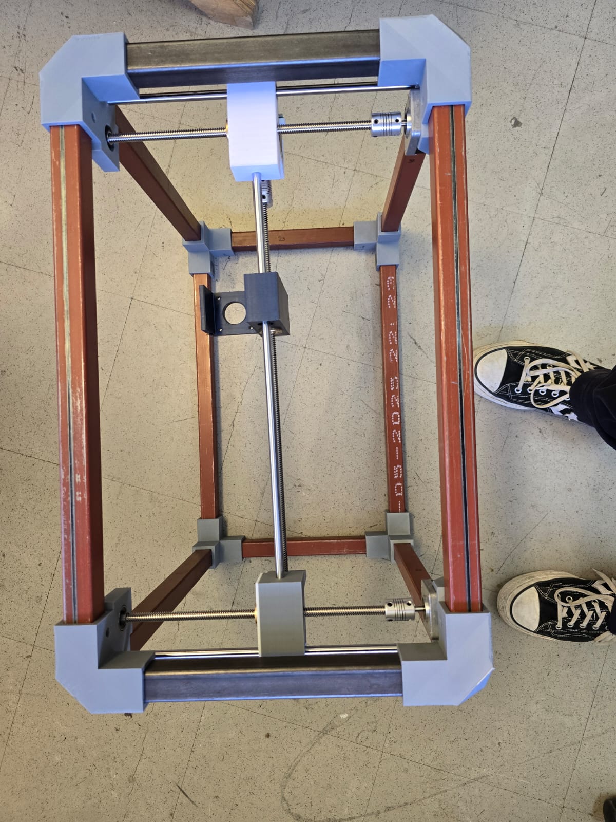
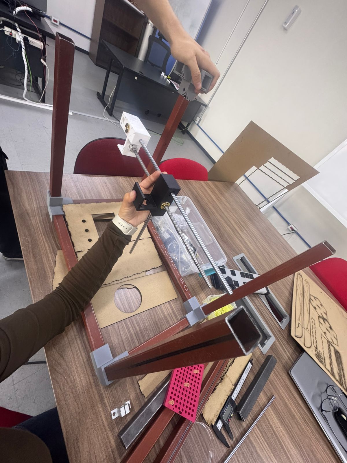
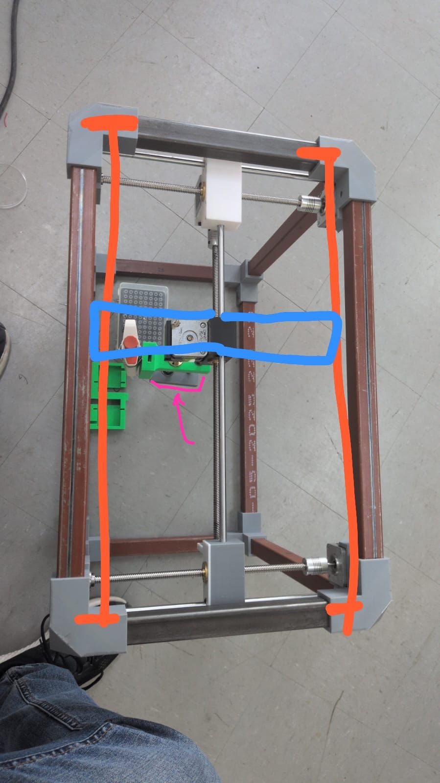
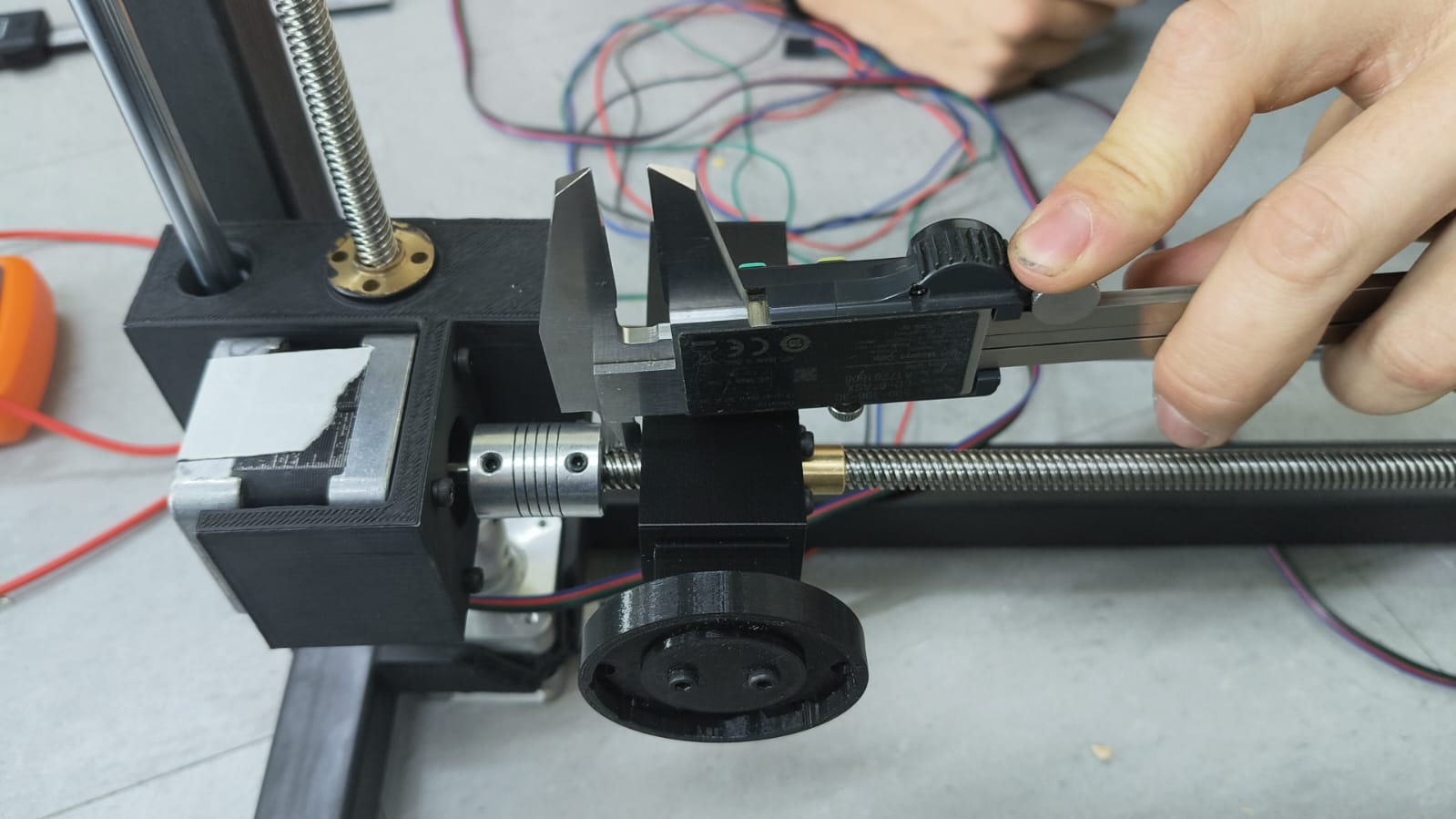
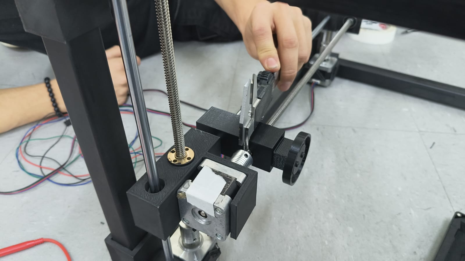
Mechanical test
With just manually moving the endless screws of the different axis in our system, we detected a MAJOR flaw: the pipette was swinging to much with every move.
This was a CRITICAL discovery, because it meant probably changing out system's position, printing new pieces or moving things around until we obtained the precission we needed.
Change of plans...
After some discussion with all team members, we came to the conclusion that changing the scope of the machine's purpose was best. The small amount of time left, work needed and material availability led us to this decision.
Once we had our minds set and our new objective clear, we got hands on at full speed.
Our new objective:
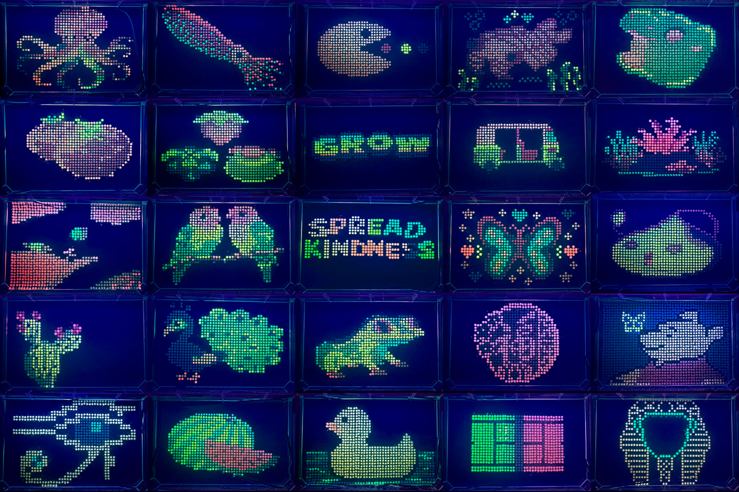
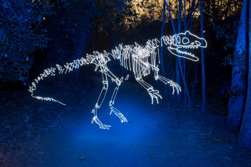
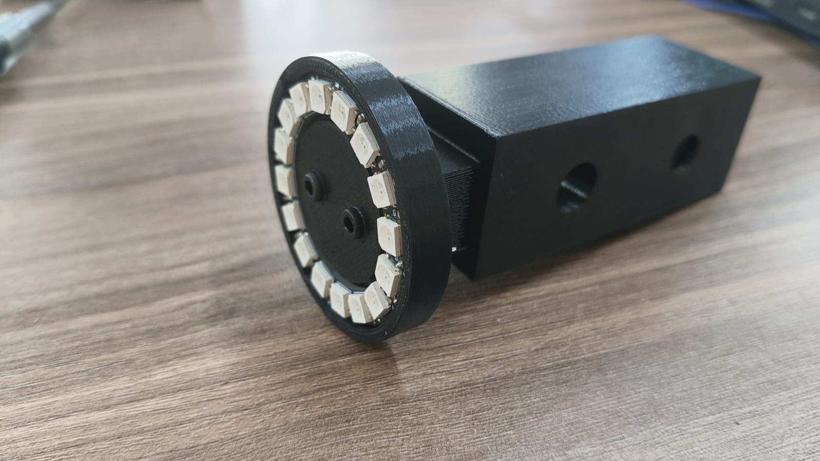
Making the best of our current working X & Y axis structure to change the pipette's (z) axis so that it holds a neopixel ring that can be recorded on a black background to make automated drawings. Something like this:
To make this possible, some things had to be removed and others added...
Remove:
- Z axis (motor, driver, endless screw, aluminum bar, etc.)
- Acrilic Base
- Pipette
- Samples
- Agar gel base
- Pipette serynges
- ESP32 D
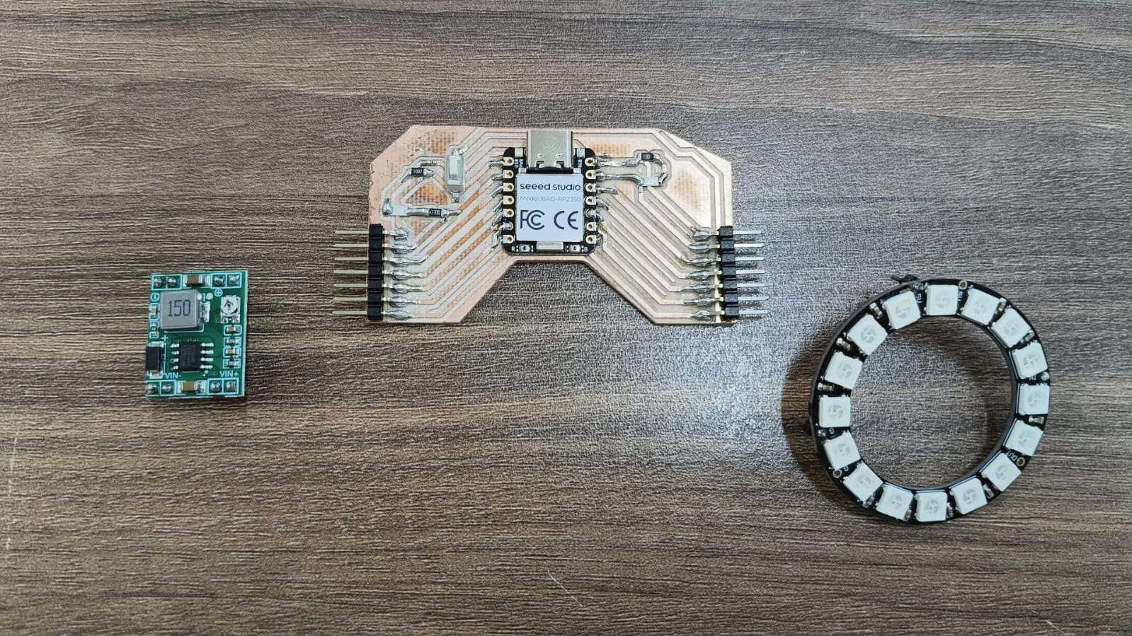
Add:
- Neopixel
- XIAO-RP2350
- ESP32 WROOM 32
- Buck MP1584
- Camera
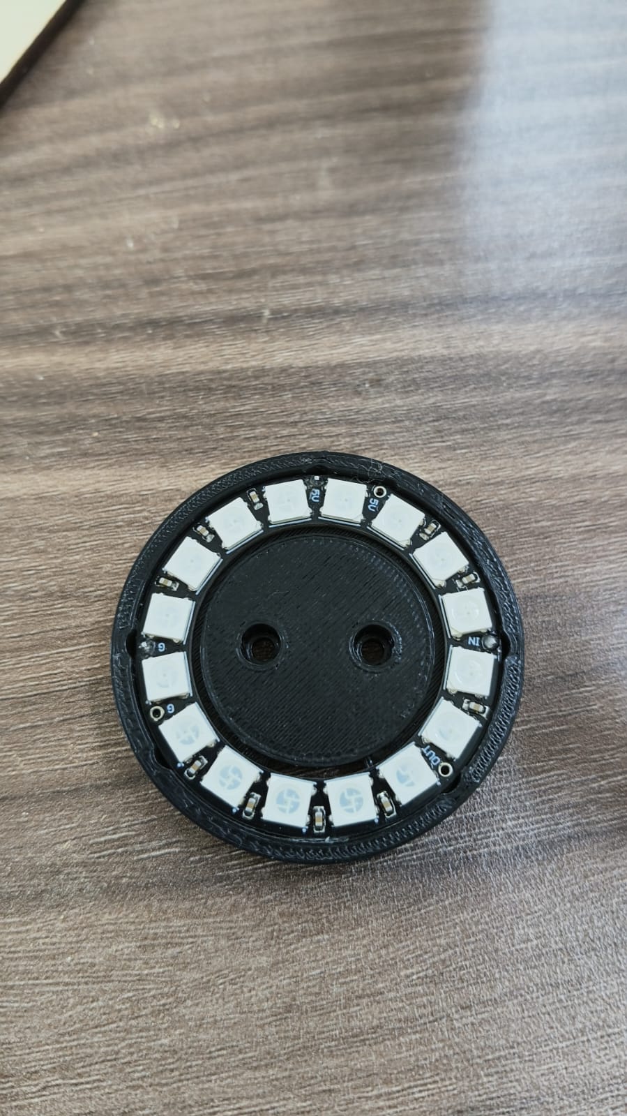
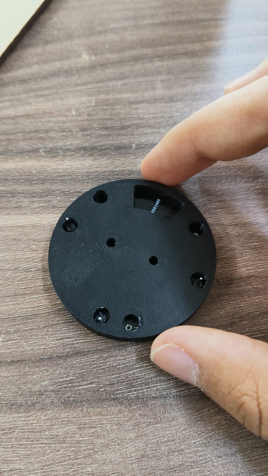
- Neopixel mount (3D designed and printed)
- Neopixel car(3D designed and printed)
- New PCB (Find all KiCad files here.)
The new materials we addded and printed:
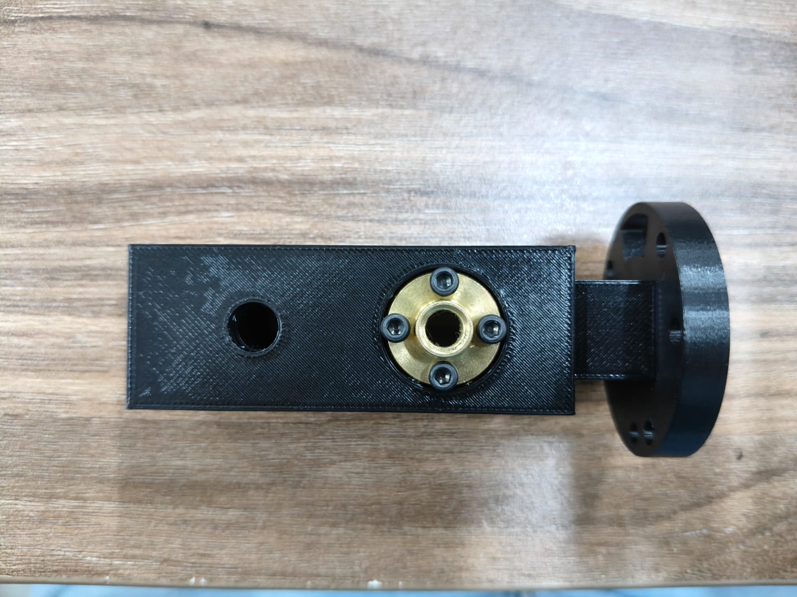
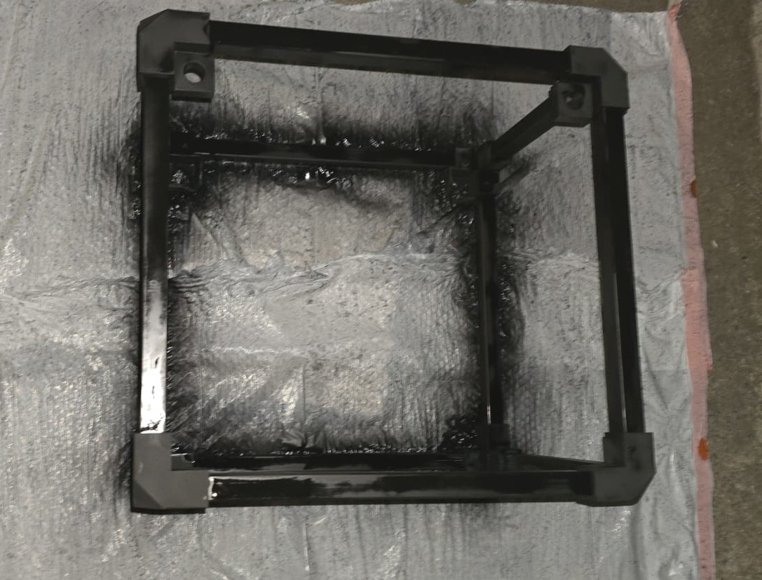
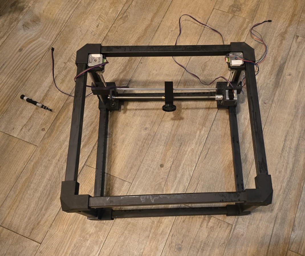
About the structure...
We had to disassemble everything, paint the structure black, remove previous Z axis elemnts and add our new newPixel ring mount on it's new car:
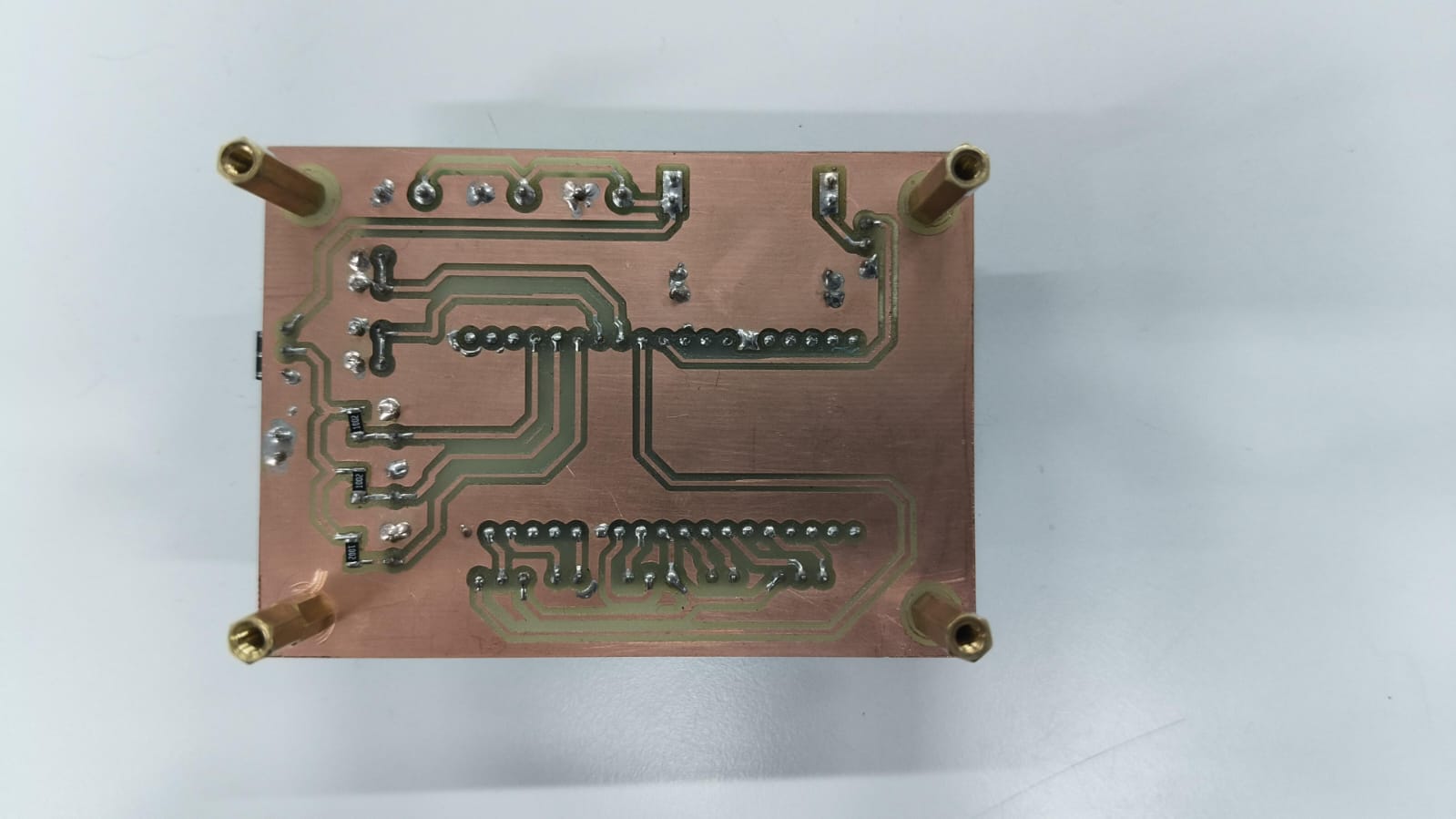
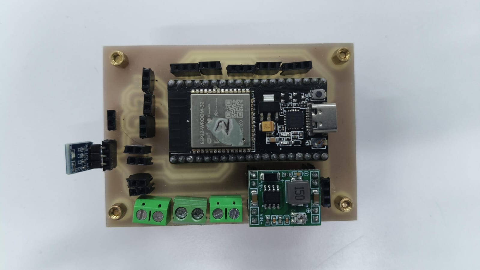
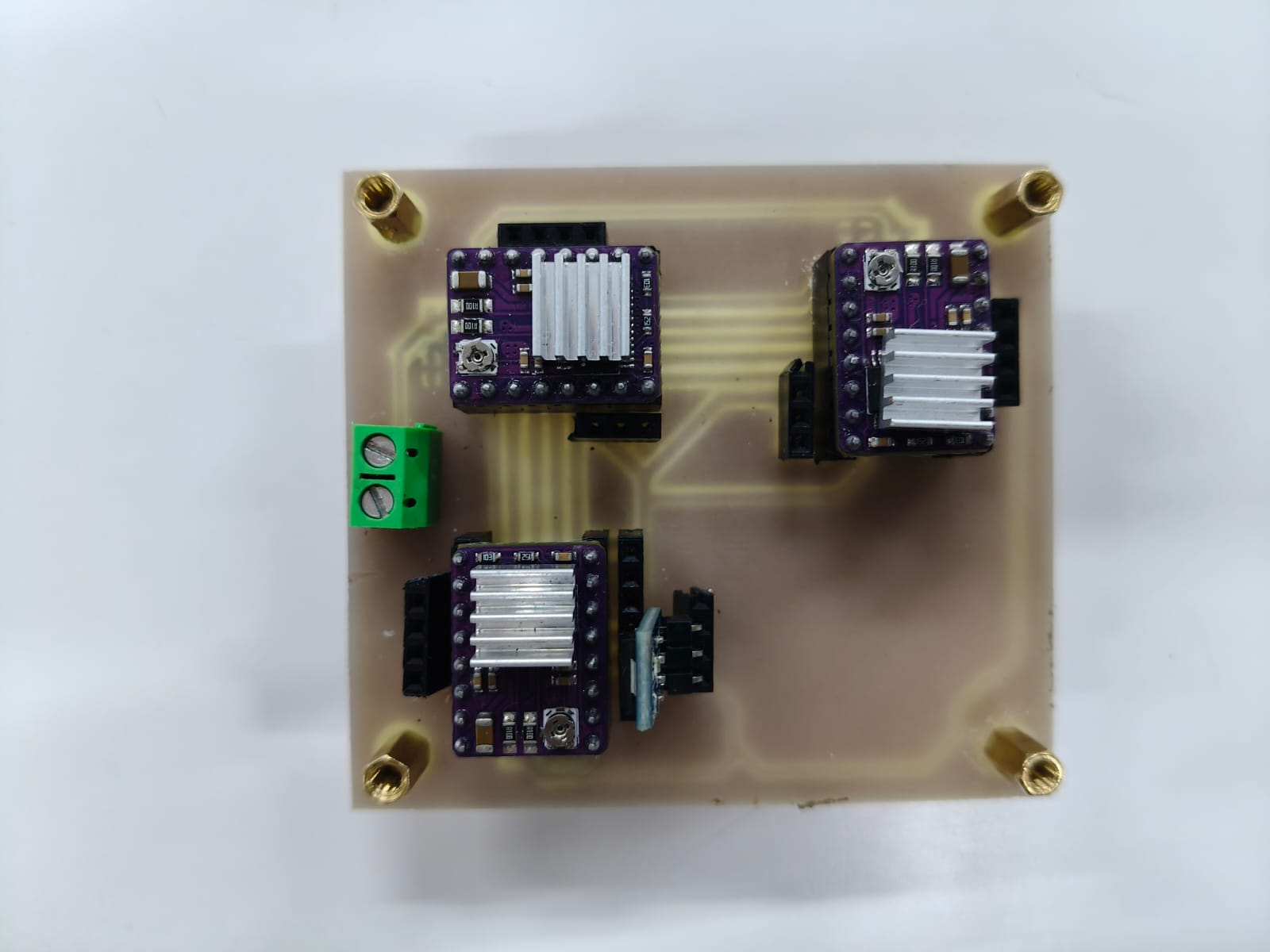
About the PCBs...
This is how they turned out:
The axis controler PCB:
The motor drivers PCB:
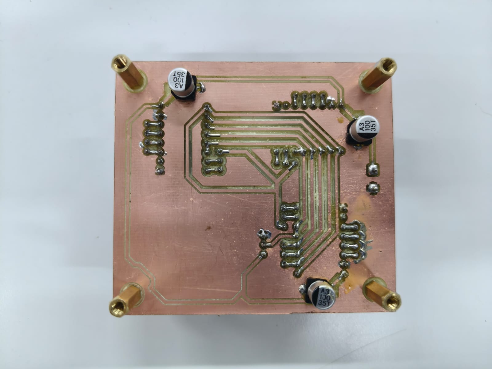
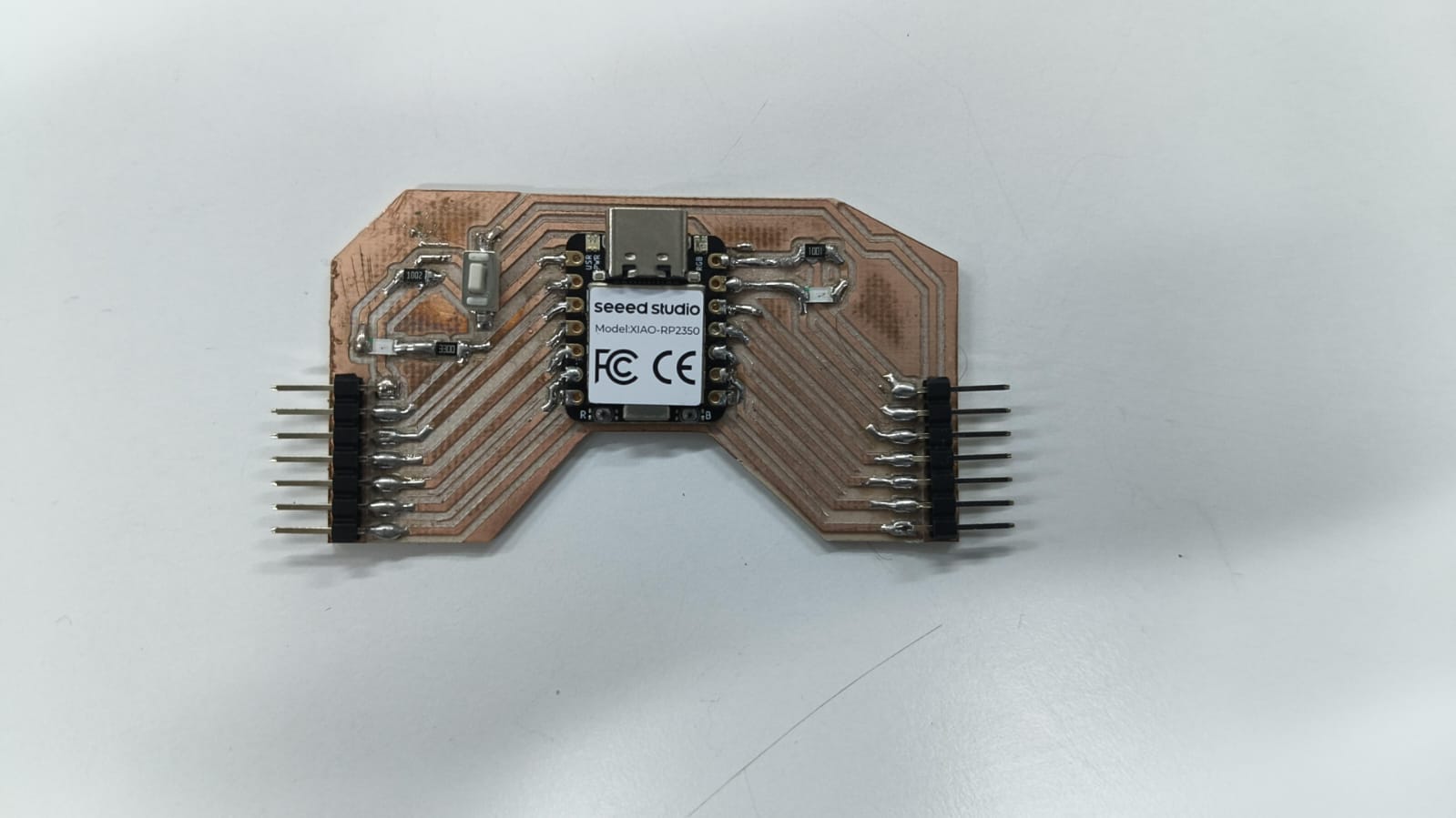
The neopixel controler PCB:
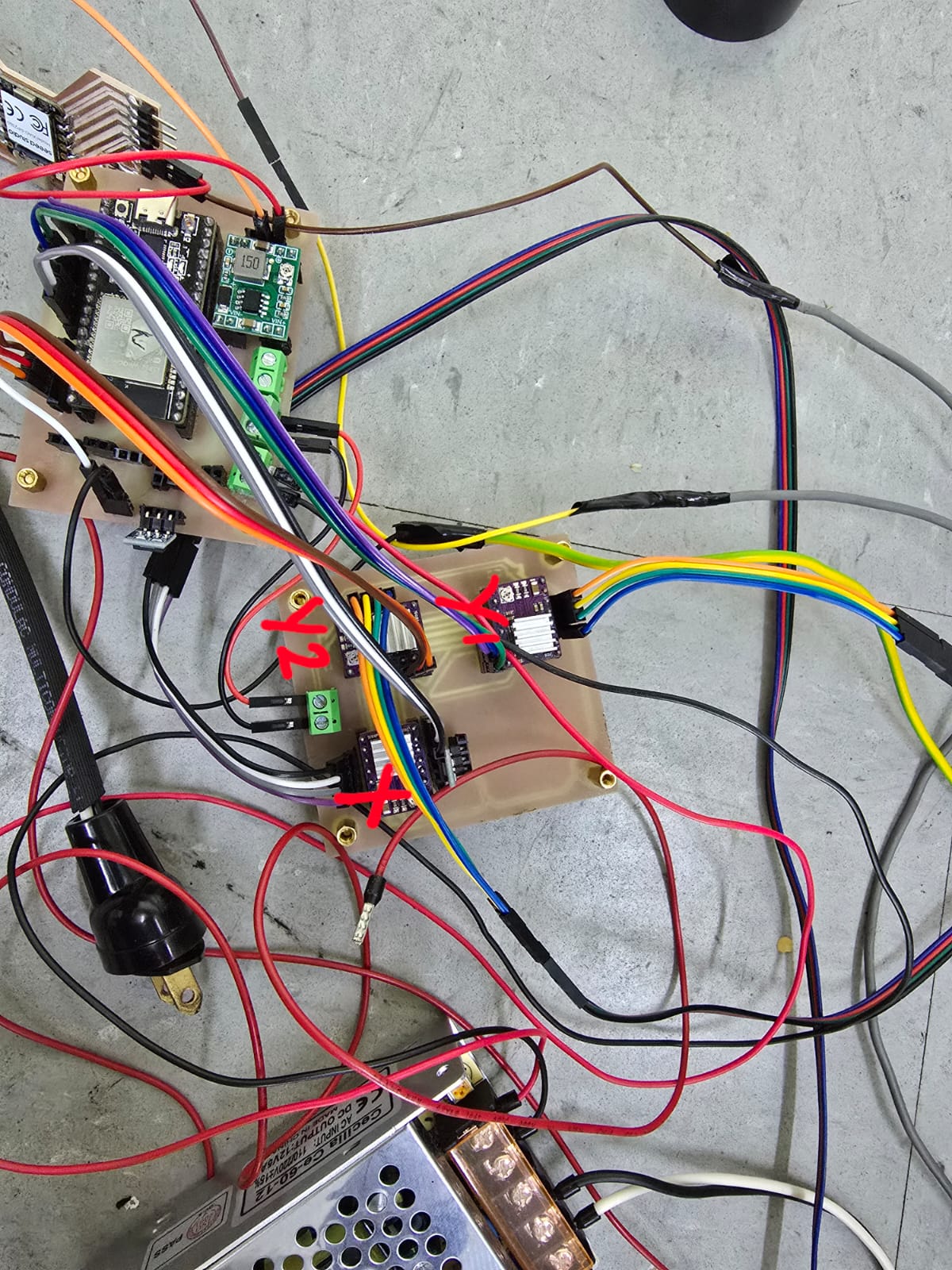
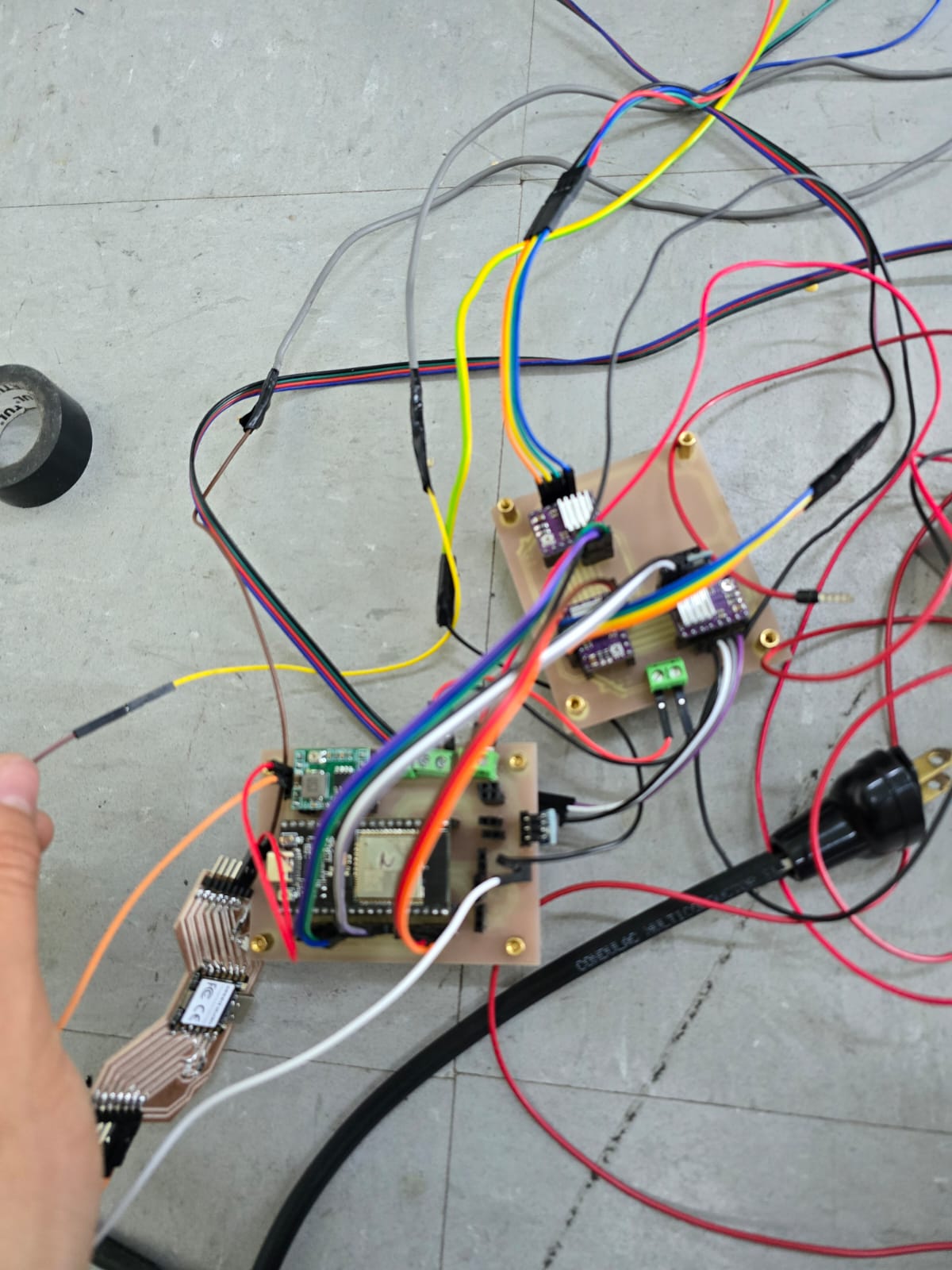
And this is how connections looked:
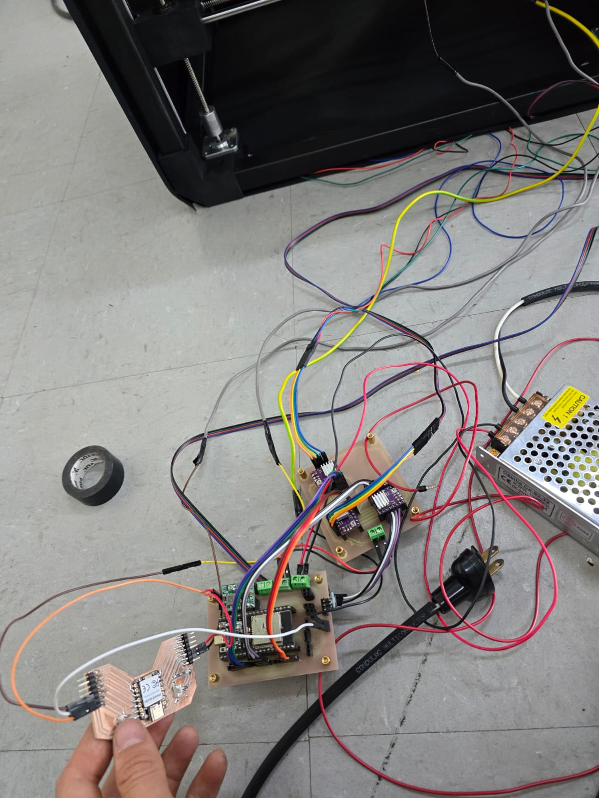
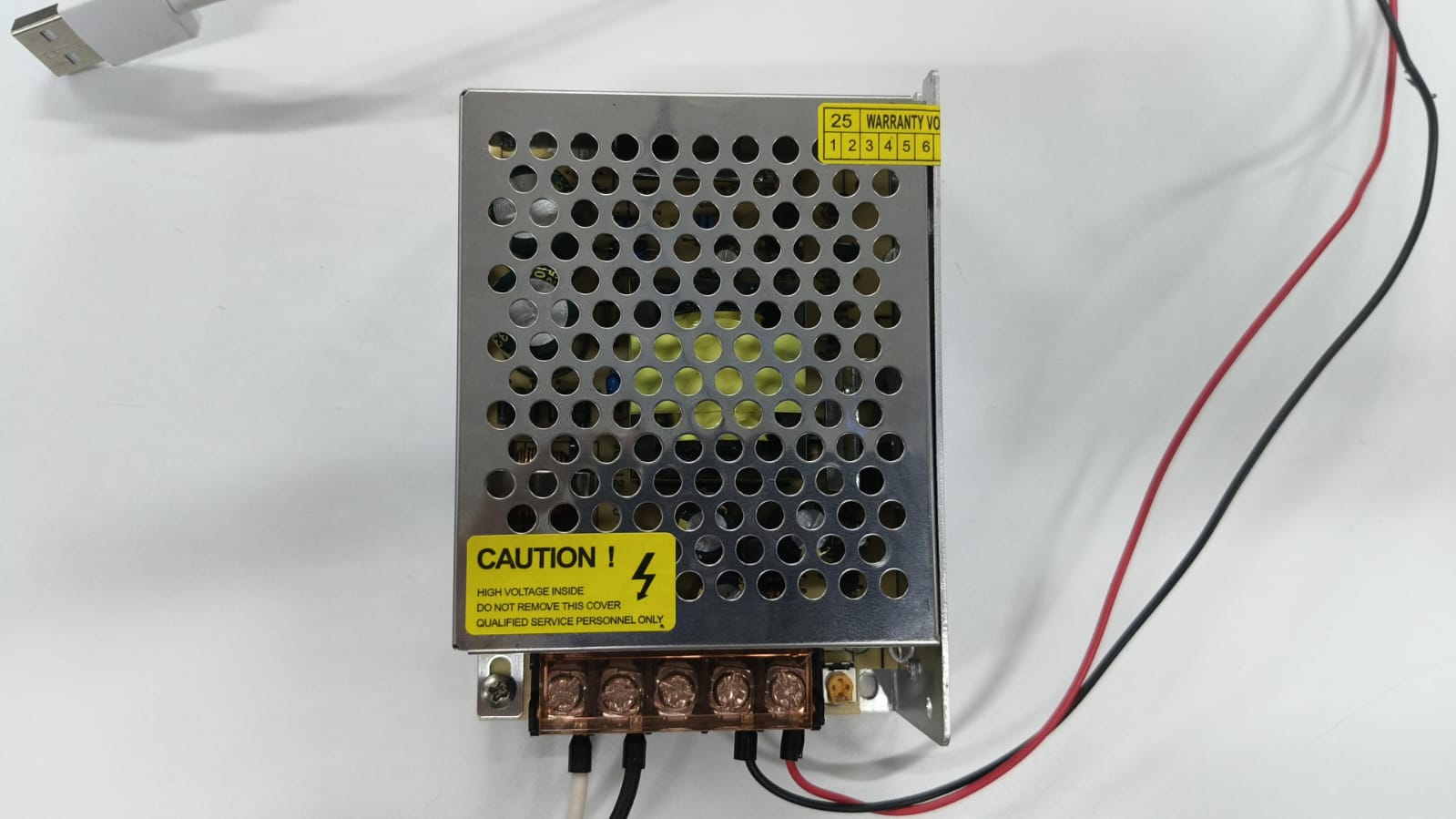
Oh, and this is the 12V and 5amp power source we used:
Testing
Of course, some tests had to be carried out before actually mounting the neoPixel:
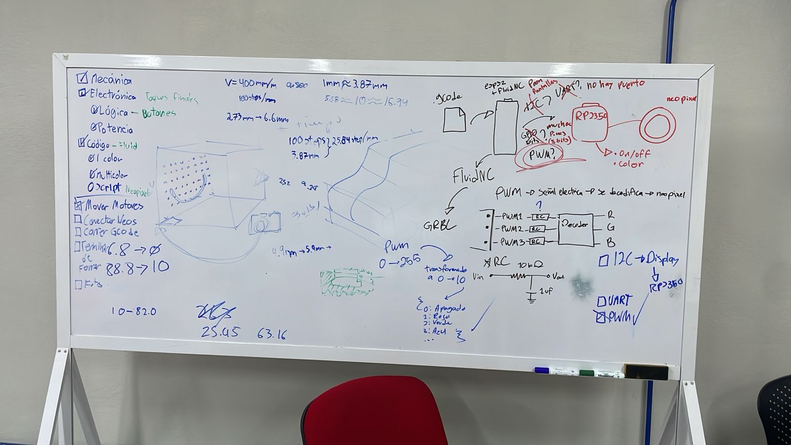
The logic used to control the neopixel was carefully planned, as we decided to use PWM communication between the XIAO and the ESP32. (After trying with I2C and not succeeding)
We also tested the 2 Y axis motors being controled by the same driver, found some soldering errors that made the twitch and fixed that:
Final touches
Once we knew everything was working, the time came to put it all together and run the final tests.
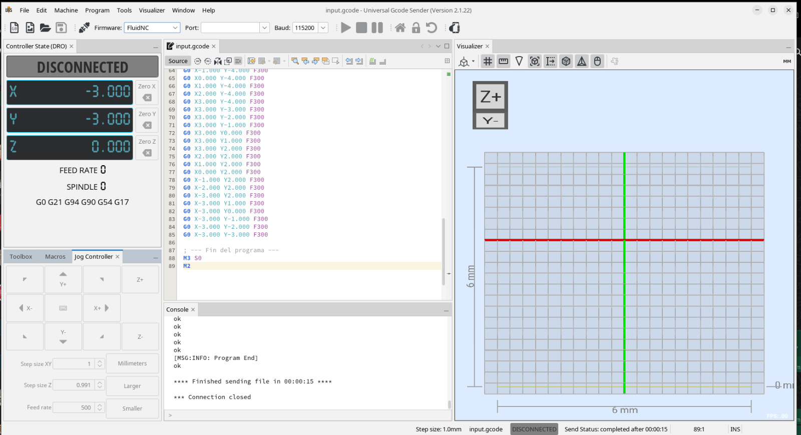
For this, we prepared a universal CNC interface and used FluidNC to control all axis: Download confuguration here.
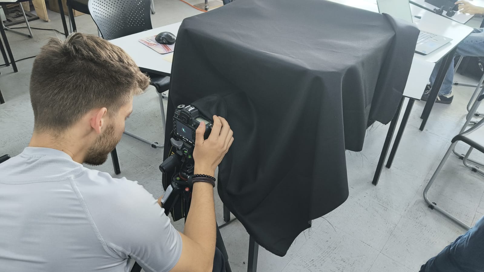
We also covered everything with a black fabric and set up our camera:
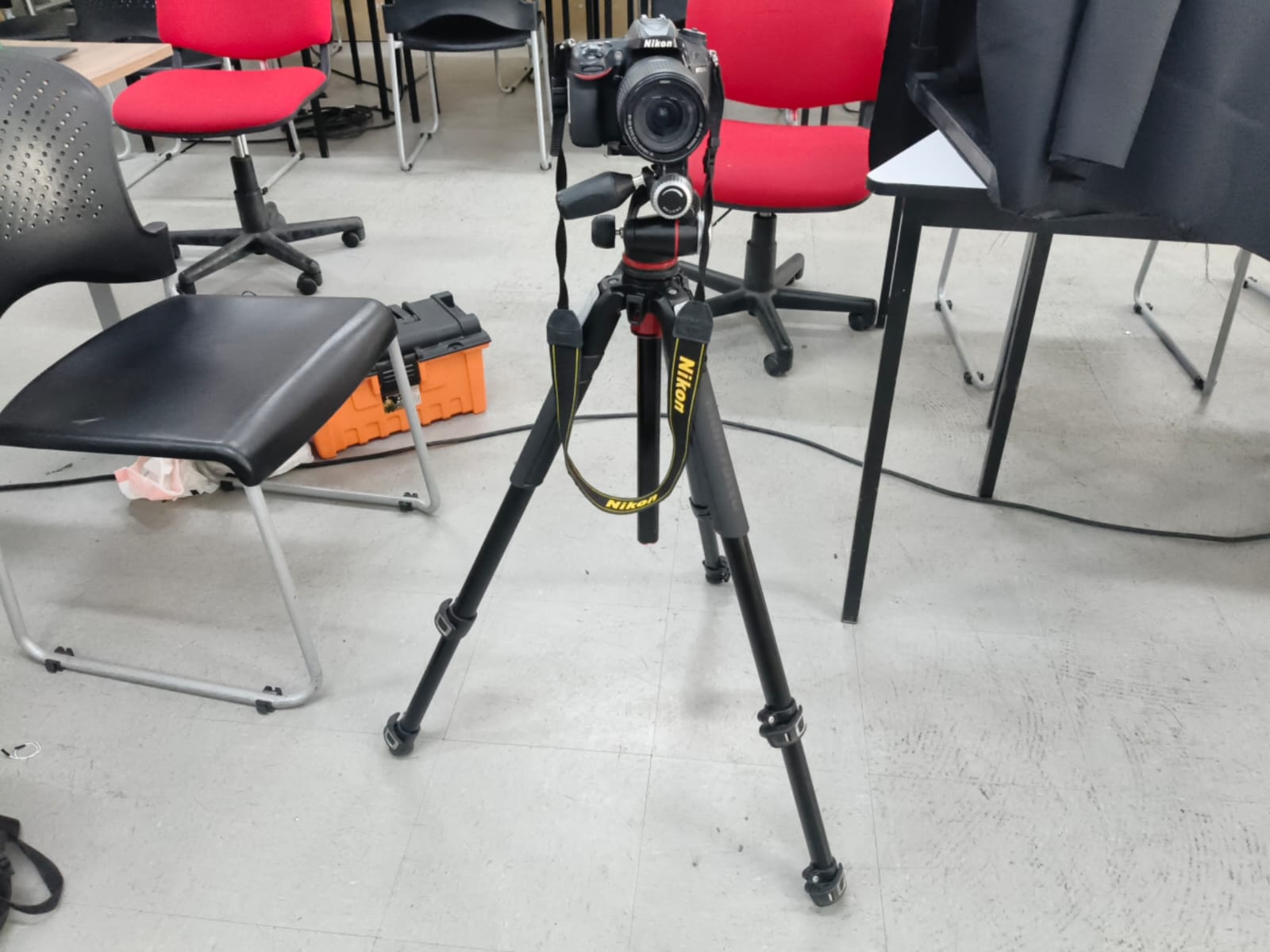
Our machine:
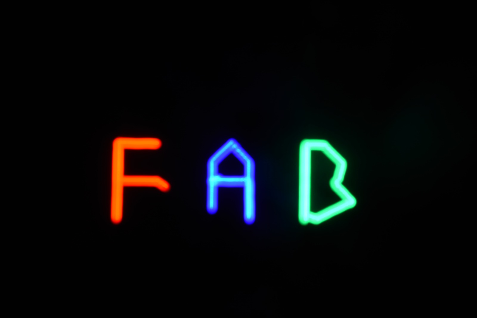
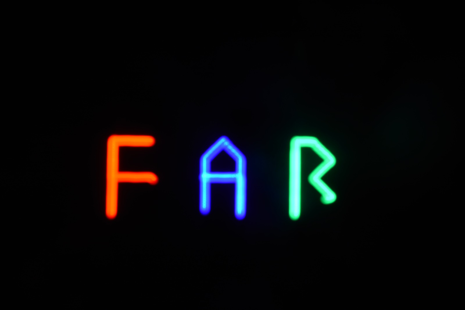
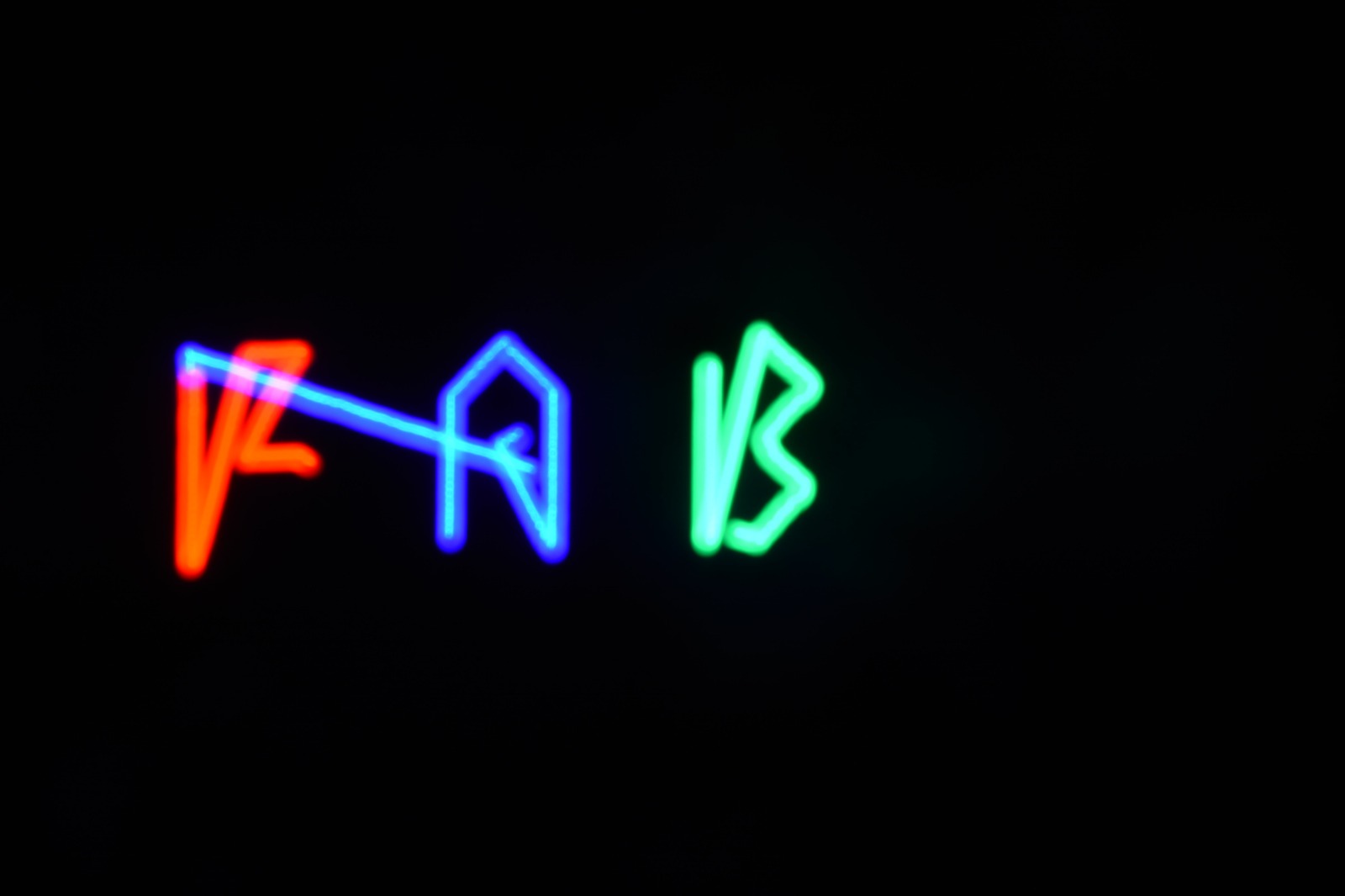
Finally, we were able to generate gcodes with This python code. and load them to the machine for it to draw with the light.
These are come of the codes we generated:
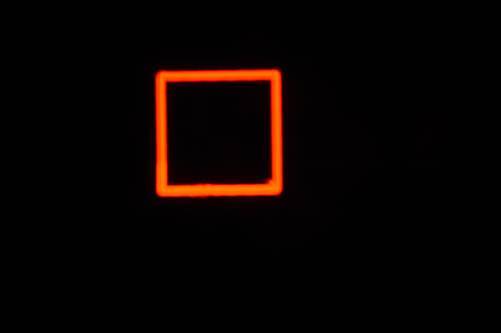
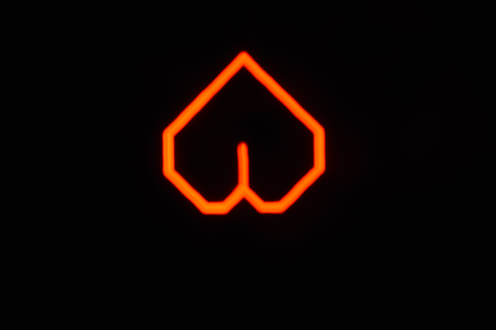
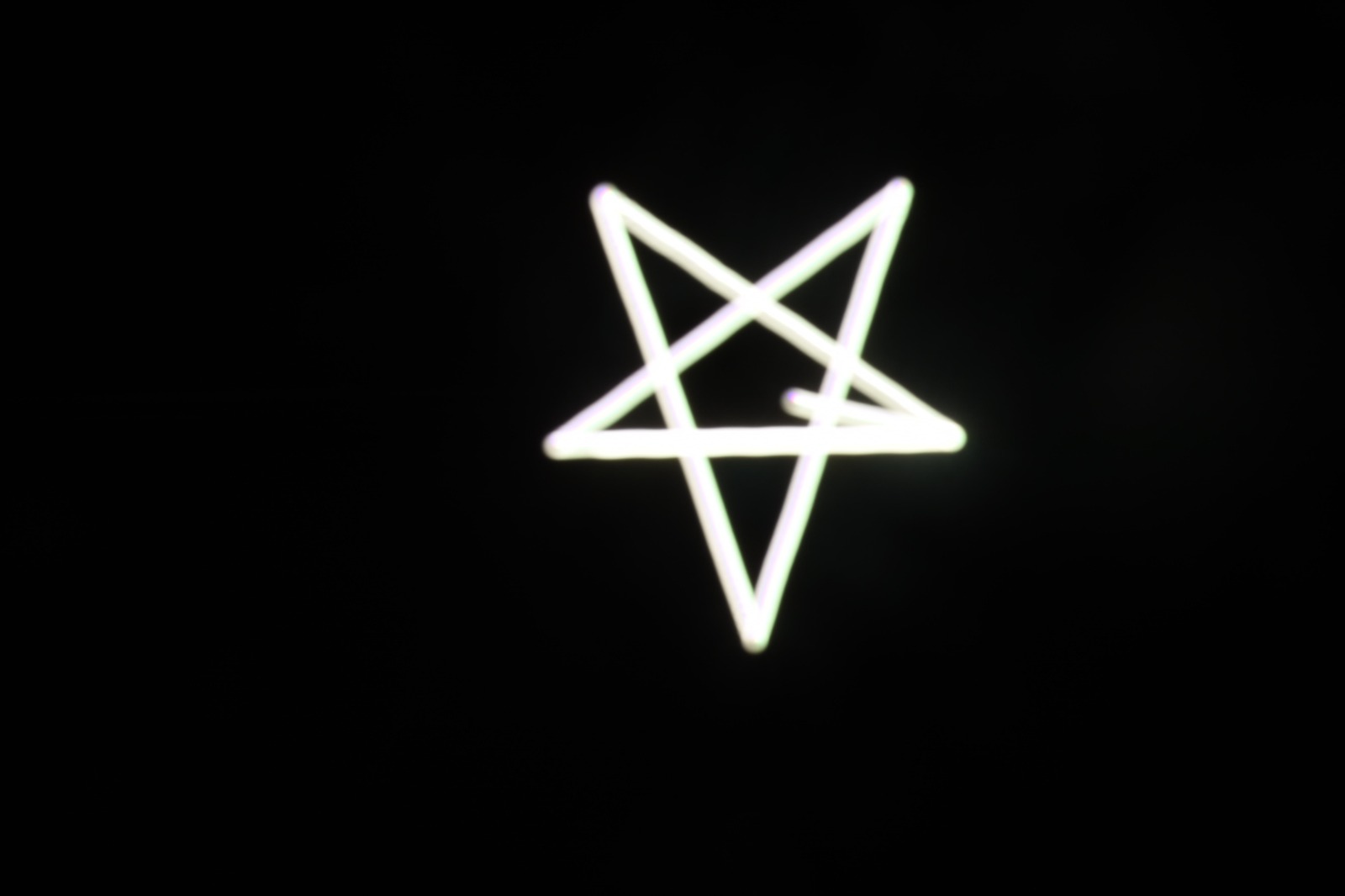
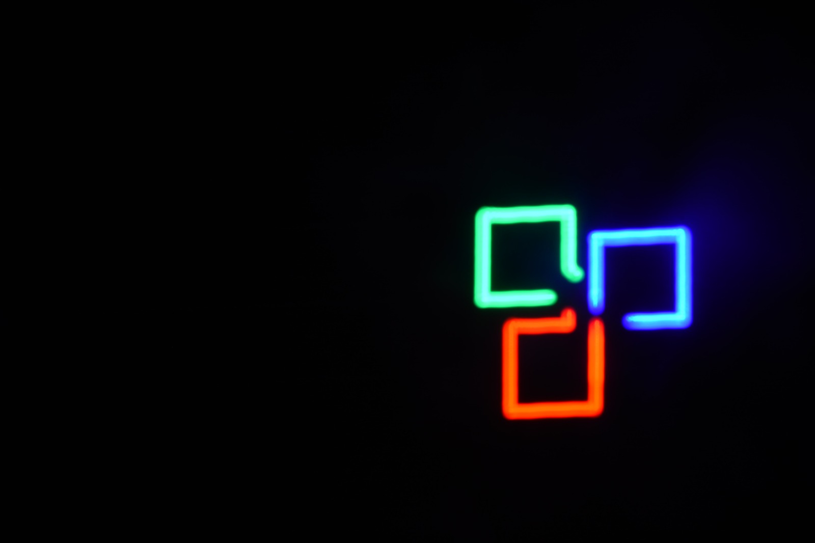
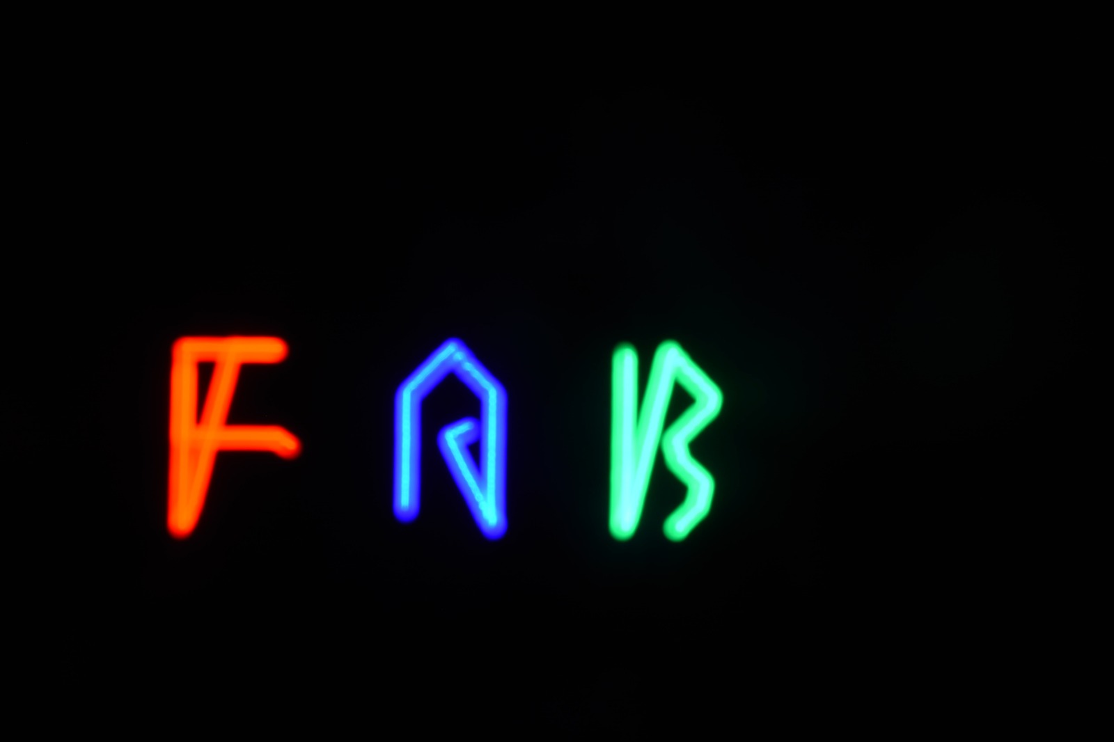
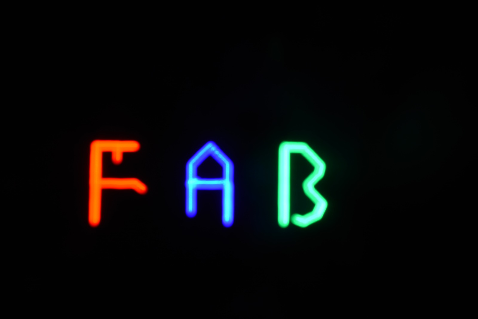
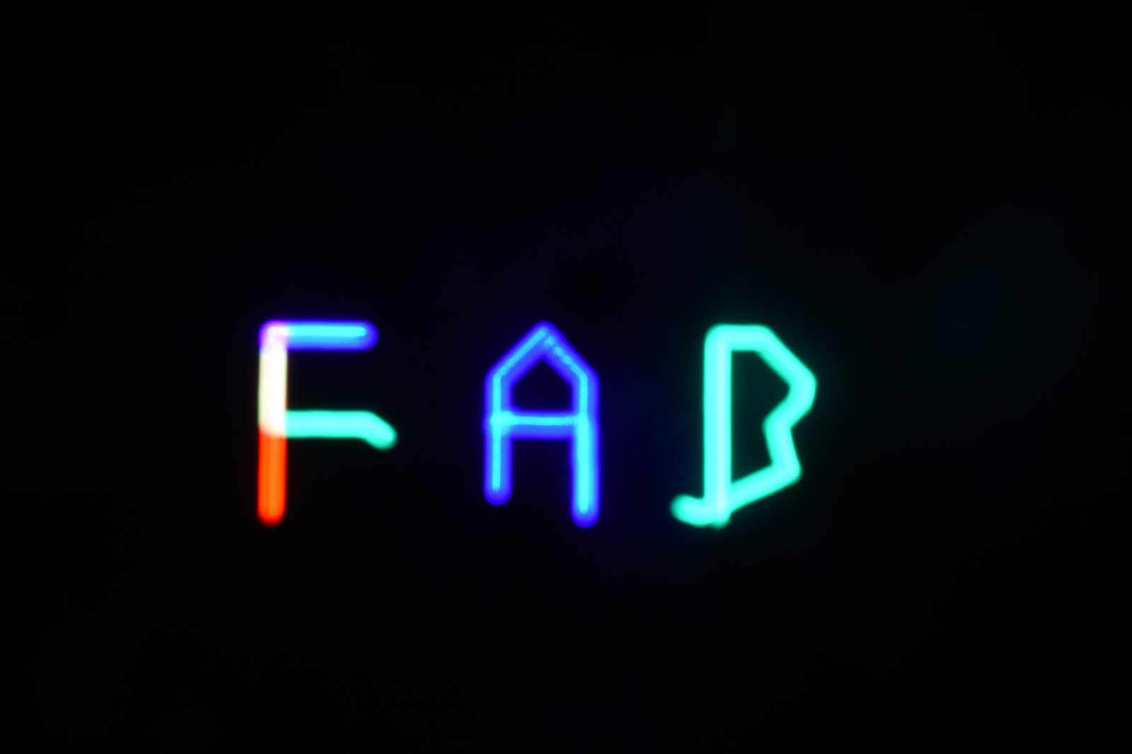
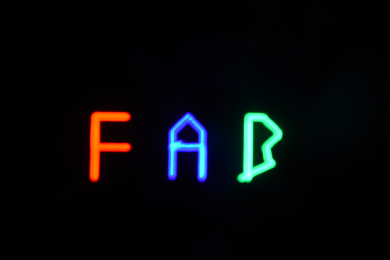
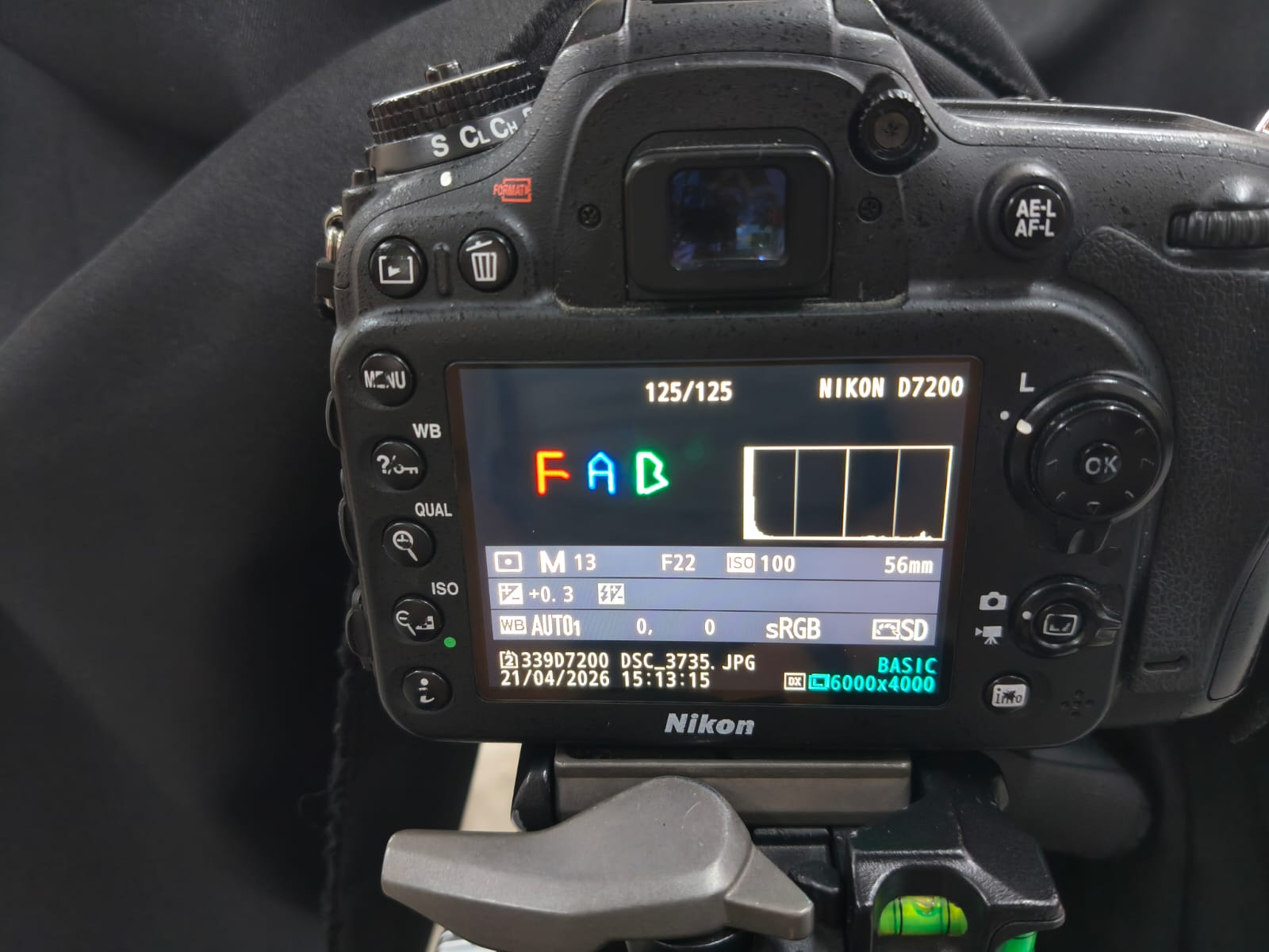
And here are the results:
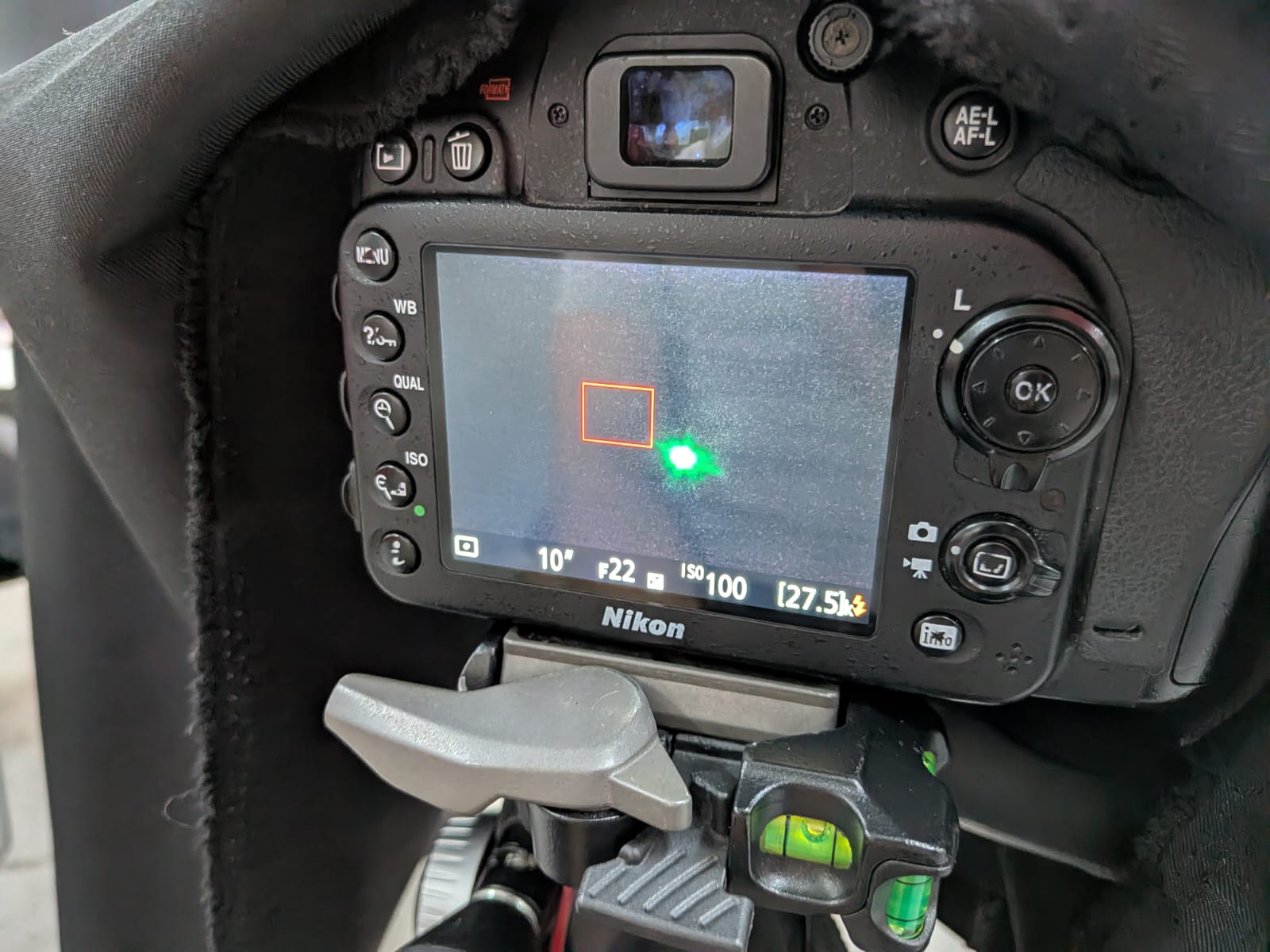
First shots with a phone:
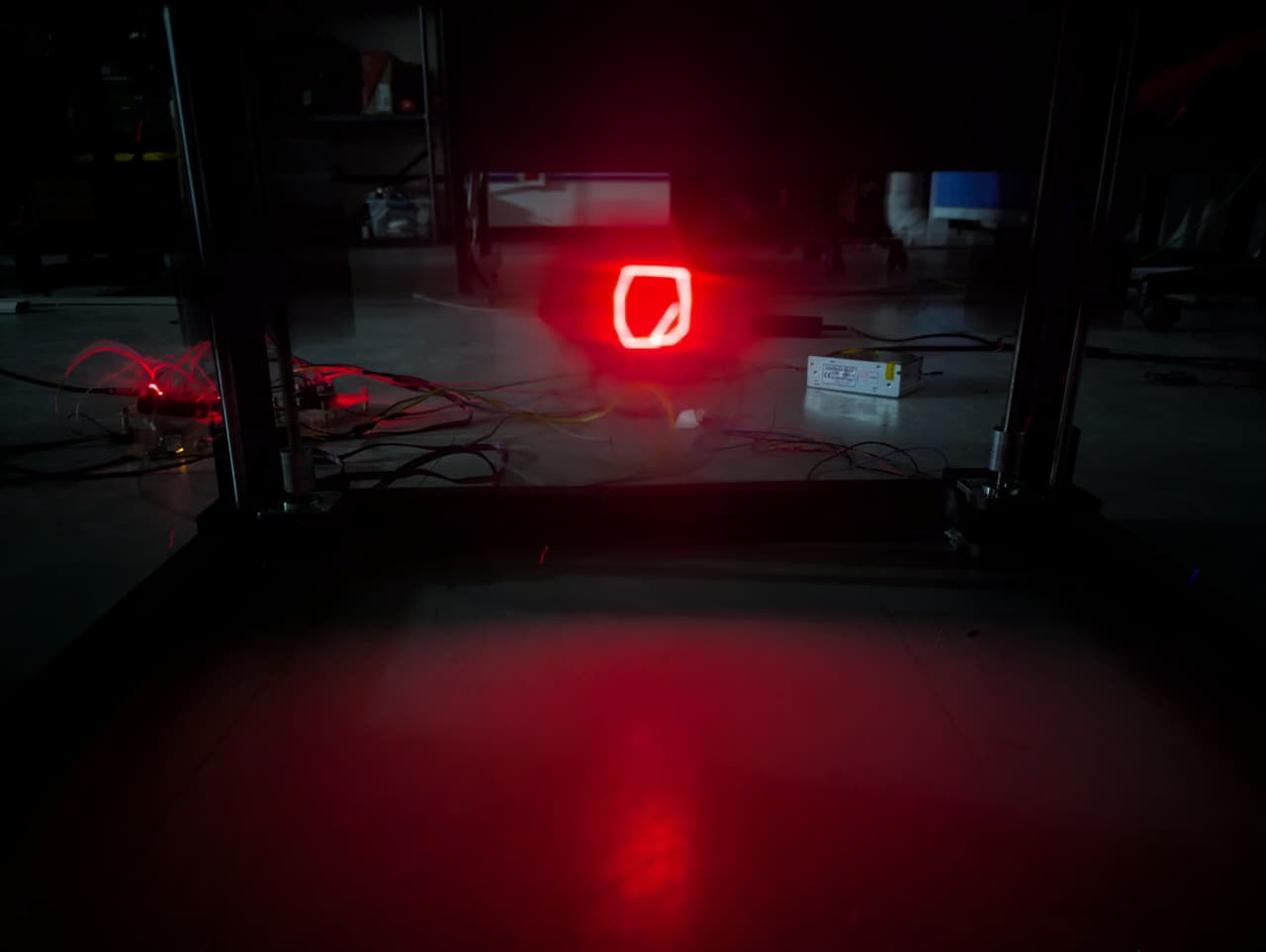
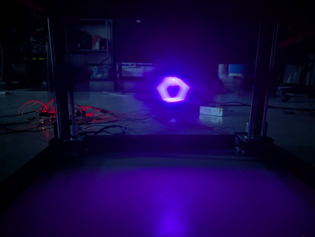
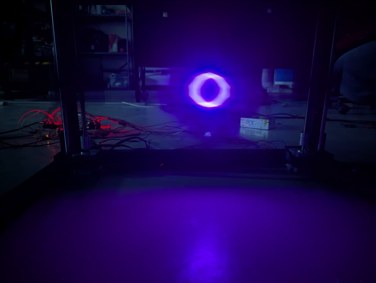
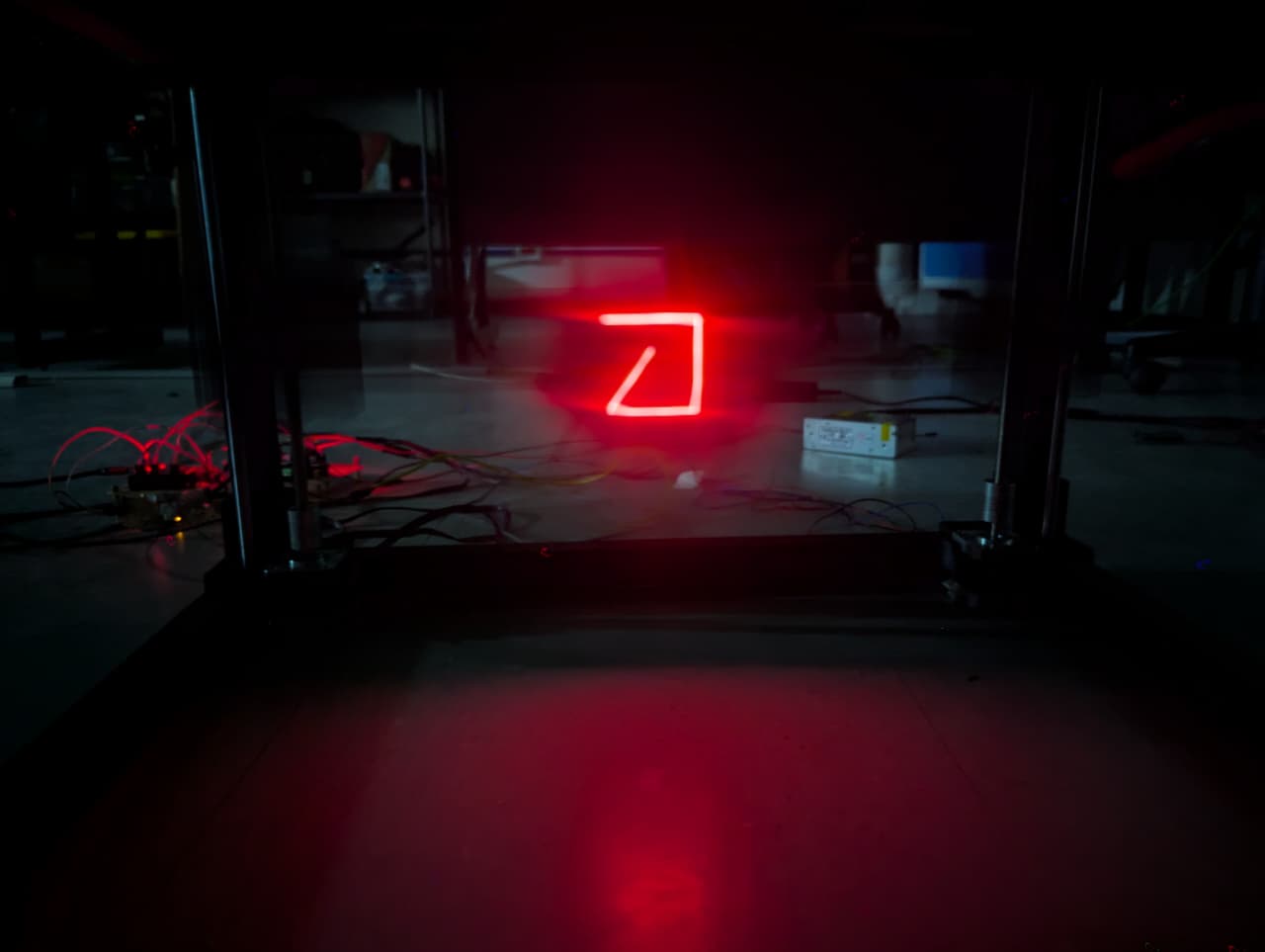
Pro camera shots: