Main Protocol
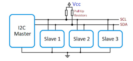
I2C communication
Fab Academy 2026
Exploring communication protocols and integrating biometric sensors using I2C communication.
I2C communication
ESP32-C6 and MAX30102
Establish communication between embedded devices and sensors.
During the group assignment we explored different communication protocols commonly used in embedded systems and IoT projects.
We analyzed how each protocol works, its advantages, limitations and possible applications depending on the project requirements.
Understanding these protocols helped me decide which communication method was the most suitable for my wearable biometric project.
Different communication protocols offer different advantages depending on speed, distance, power consumption and system complexity.
During this week I researched and tested several common protocols used in embedded systems and IoT applications.
Connect the two boards like this:
Wire.h.Wire.begin(SDA_PIN, SCL_PIN, frequency).Wire.beginTransmission(address) and Wire.write(...).Wire.endTransmission().Wire.requestFrom(...).Wire.read().Wire.h.Wire.onReceive(...).Wire.onRequest(...).Wire.begin(address, SDA_PIN, SCL_PIN, frequency).I2C is recommended in situations where you need to connect multiple low-speed devices using only two wires (SDA and SCL). It is especially useful in embedded systems where pin availability is limited.
I2C is not ideal for high-speed or long-distance communication. In those cases, protocols like SPI or UART may be more suitable.
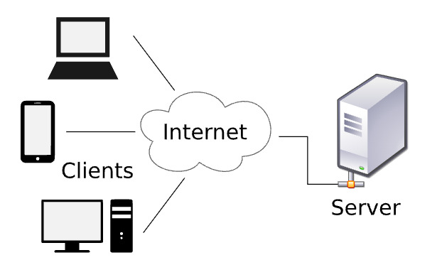
WiFi.h and WebServer.h.WiFi.begin(...).WebServer object.server.on(...).server.begin().server.handleClient() inside the main loop.Two boards can communicate through HTTP when both are connected to the same Wi-Fi network and one board knows the IP address of the other.
In this setup:
GET /sensor or GET /led/on to Board A.Wi-Fi with HTTP is recommended when you need wireless communication between devices that are already connected to the same network or have access to a router or hotspot.
Wi-Fi HTTP is not ideal for low-power applications or real-time critical systems, since it has higher latency and power consumption compared to simpler communication protocols.
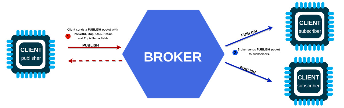
WiFi.h and PubSubClient.h.MQTT over Wi-Fi is recommended for lightweight, efficient, and scalable communication between embedded devices and servers, especially in IoT systems.
MQTT is not ideal for direct device-to-device communication without a broker, or for applications that require complex request-response logic like HTTP.
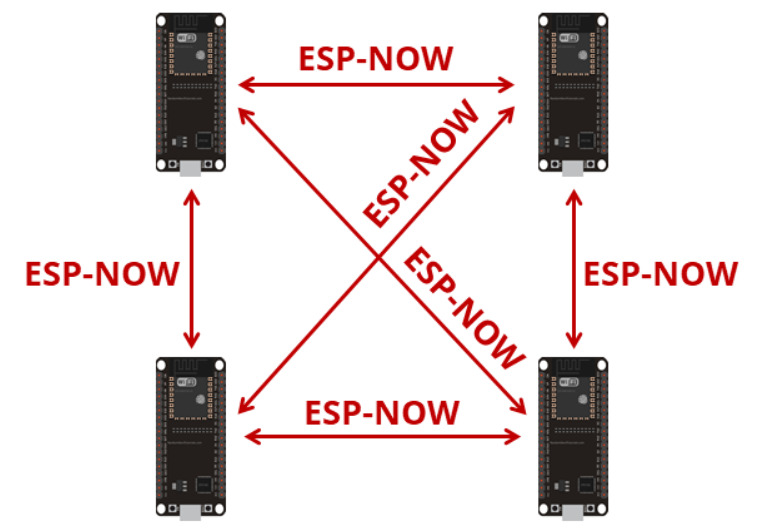
Each receiver has a unique MAC address. The sender must know the receiver’s MAC address in order to communicate with it.
A simple way to find it is to upload the following temporary sketch to the receiver board once:
#include <WiFi.h>

            void setup() {
            Serial.begin(115200);
            WiFi.mode(WIFI_STA);
            Serial.println(WiFi.macAddress());
            }

            void loop() {
            }
After uploading, open the Serial Monitor to read and copy the MAC address. Then, place that MAC address in the sender code.
WiFi.h and esp_now.h.WIFI_STA.esp_now_send(...).WiFi.h and esp_now.h.WIFI_STA.ESP-NOW is recommended for fast, low-power, and direct communication between ESP devices without the need for a Wi-Fi router or internet connection.
ESP-NOW is not suitable for large data transfers, internet-based communication, or systems that require standard IP networking and web integration.

BLE is recommended for short-range, low-power wireless communication between embedded devices, smartphones, and tablets.
BLE is not suitable for high data-rate applications, long-range communication, or continuous streaming of large datasets.
Study different communication protocols and compare their characteristics.
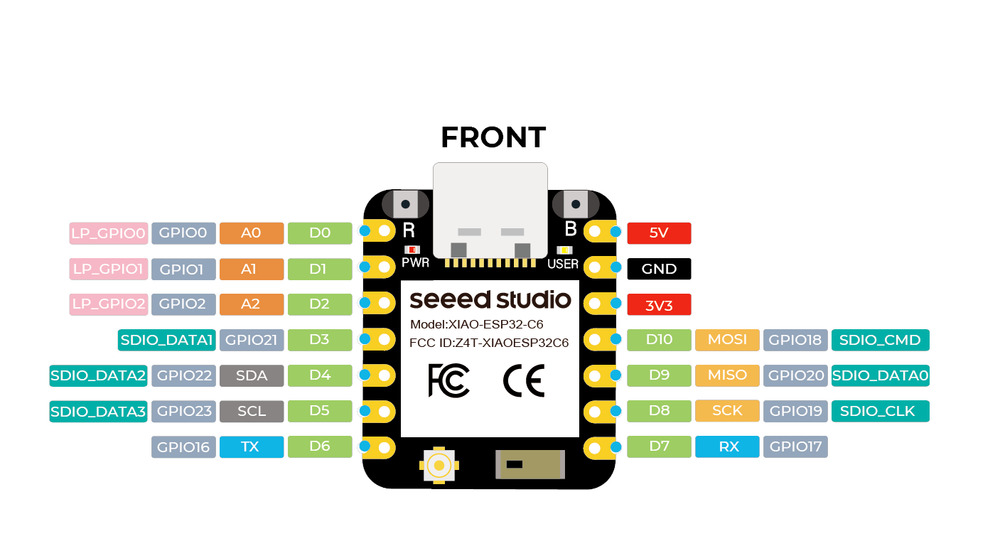
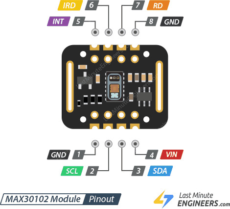
Connect the MAX30102 sensor to the ESP32-C6 using I2C communication.
Validate stable communication and biometric data acquisition.
Since the MAX30102 sensor communicates using SDA and SCL pins and the ESP32-C6 board is physically close to the sensor, I2C communication was the best option for this project.
I2C simplifies wiring, reduces the number of required pins and provides stable communication between embedded devices.
These are the pinouts used for the connection:
The code initializes the MAX30102 sensor using I2C communication and continuously processes biometric heart rate data.
The program also filters noise, calculates BPM averages and activates physical outputs depending on heart rate variations.
#include <Wire.h>
#include "MAX30105.h"
#include "heartRate.h"

MAX30105 particleSensor;

const int LED_PIN = D1;
const int MOTOR_PIN = D2;

const byte RATE_SIZE = 12;

byte rates[RATE_SIZE];

byte rateSpot = 0;

long lastBeat = 0;

float beatsPerMinute;

int beatAvg;

bool baseEstablecida = false;

int muestrasCalibracion = 0;

const int TOTAL_MUESTRAS_CAL = 20;

float sumaCalibracion = 0;

float pulsoBase = 0;

int altosConsecutivos = 0;

const int MINIMO_PULSOS_ALTO = 3;

bool alertaActiva = false;

void setup() {

  Serial.begin(115200);

  delay(1000);

  pinMode(LED_PIN, OUTPUT);

  pinMode(MOTOR_PIN, OUTPUT);

  digitalWrite(LED_PIN, LOW);

  digitalWrite(MOTOR_PIN, LOW);

  Wire.begin(22, 23);

  if (!particleSensor.begin(Wire, I2C_SPEED_FAST)) {

    Serial.println("MAX30102 no encontrado");

    while (1);

  }

  byte ledBrightness = 60;

  byte sampleAverage = 1;

  byte ledMode = 2;

  int sampleRate = 200;

  int pulseWidth = 411;

  int adcRange = 4096;

  particleSensor.setup(
    ledBrightness,
    sampleAverage,
    ledMode,
    sampleRate,
    pulseWidth,
    adcRange
  );

}

void loop() {

  long irValue = particleSensor.getIR();

  if (irValue < 50000) {

    digitalWrite(LED_PIN, LOW);

    digitalWrite(MOTOR_PIN, LOW);

    delay(500);

    return;

  }

  if (checkForBeat(irValue) == true) {

    long delta = millis() - lastBeat;

    lastBeat = millis();

    beatsPerMinute = 60 / (delta / 1000.0);

    if (beatsPerMinute < 140 &&
        beatsPerMinute > 40) {

      rates[rateSpot++] =
      (byte)beatsPerMinute;

      rateSpot %= RATE_SIZE;

      int sum = 0;

      for (byte x = 0; x < RATE_SIZE; x++) {

        sum += rates[x];

      }

      beatAvg = sum / RATE_SIZE;

      if (!baseEstablecida) {

        sumaCalibracion += beatsPerMinute;

        muestrasCalibracion++;

        if (muestrasCalibracion >=
            TOTAL_MUESTRAS_CAL) {

          pulsoBase =
          sumaCalibracion /
          TOTAL_MUESTRAS_CAL;

          baseEstablecida = true;

        }

      }

      else {

        float dif =
        beatAvg - pulsoBase;

        if (dif >= 4.0) {

          altosConsecutivos++;

          if (altosConsecutivos >=
              MINIMO_PULSOS_ALTO)

            alertaActiva = true;

        }

        else {

          altosConsecutivos = 0;

          alertaActiva = false;

        }

        if (alertaActiva) {

          digitalWrite(LED_PIN, HIGH);

          digitalWrite(MOTOR_PIN, HIGH);

        }

        else {

          digitalWrite(LED_PIN, LOW);

          digitalWrite(MOTOR_PIN, LOW);

        }

      }

    }

  }

}
Initializes I2C communication and prepares the MAX30102 sensor for biometric readings.
Uses averaging and filtering methods to reduce noise and stabilize BPM measurements.
Establishes a baseline heart rate before entering monitoring mode.
Activates the LED and vibration motor when BPM exceeds the baseline threshold.
During testing I monitored the BPM values through the Serial Monitor to validate stable communication and heart rate detection.
Wrist movement still generates false BPM peaks during measurements.
Noisy readings can still affect the baseline BPM calculation.
The infrared readings are highly sensitive to pressure and movement.
Incorrect wiring or unstable connections can interrupt I2C communication.
This week is directly related to my wearable biometric project because communication between the sensor and the microcontroller is essential for real-time monitoring.
I2C communication allows stable biometric data transfer while keeping the wearable system compact and efficient.
In future iterations I may integrate BLE or ESP-NOW to send biometric information wirelessly to external devices.
Stable communication is critical for reliable biometric sensing.
I2C simplifies the internal wiring of the wearable system.
Wireless communication protocols could expand the project capabilities.