Main Devices
LED and vibration motor
Fab Academy 2026
Interfacing physical output devices such as LEDs and vibration motors with biometric heart rate data.
LED and vibration motor
MAX30102 heart rate sensor
Trigger physical feedback depending on heart rate variations.
During the group assignment we learned how to measure the power consumption of output devices using different electronic tools.
We applied concepts such as Ohm’s Law and Joule’s Law to better understand voltage, current and power relationships.
We also used instruments like a multimeter, USB tester and clamp ammeter to compare measurements in real situations.
This assignment helped me better understand how output devices behave electrically and how important current consumption is when designing embedded systems.
Microcontrollers can control different output devices such as LEDs, buzzers, motors, relays and displays.
These devices allow the system to interact with the physical world by producing light, sound, movement or visual feedback.
The simplest control method uses digital outputs where pins are configured HIGH or LOW to activate devices.
For more advanced control, PWM (Pulse Width Modulation) can regulate intensity or speed depending on the application.
Used to switch devices on and off.
Allows smooth brightness and motor speed control.
Transistors and MOSFETs help control devices that require higher current.
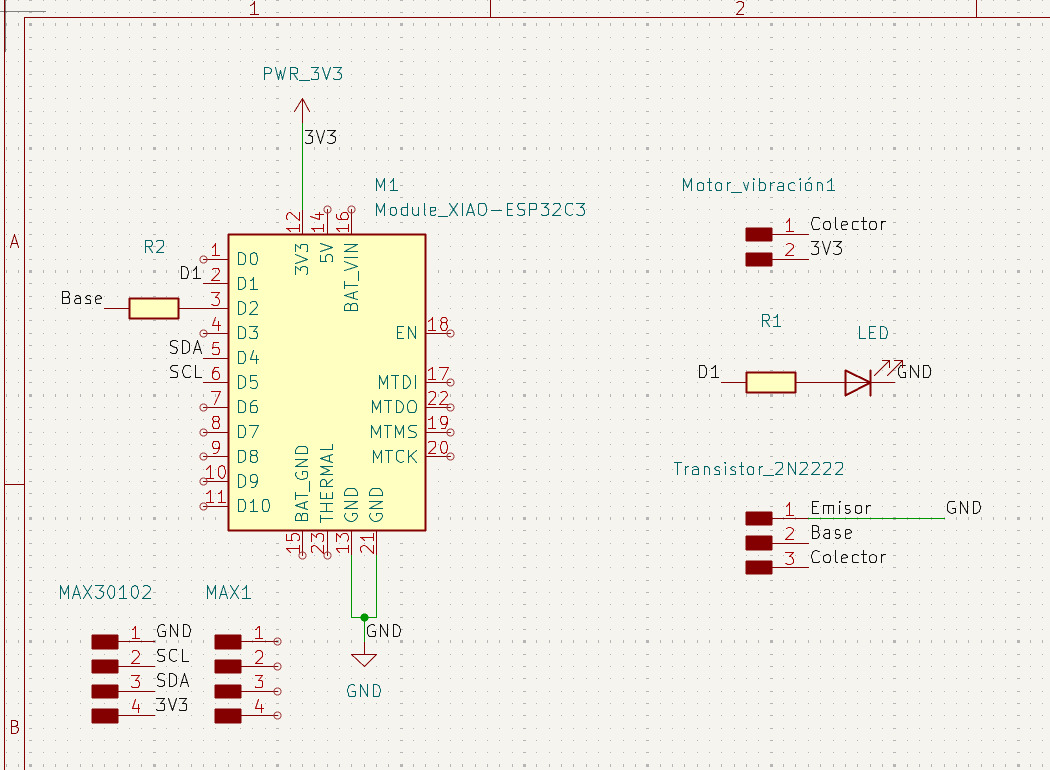
For this week I designed a PCB that includes an LED and a vibration motor connected to my biometric monitoring system.
The idea is that both actuators activate depending on the heart rate signal received from the sensor.
This assignment is important because it represents another step toward the development of my final wearable project.
Provides visual feedback when BPM increases above the threshold.
Generates haptic feedback to alert the user.
Combines biometric sensing with physical response systems.
First, I tested the logic using a protoboard before integrating everything into the PCB.
I monitored the BPM values through the serial monitor to verify that the system correctly detected heart rate changes.
Once the logic worked correctly, I tested the LED and vibration motor activation using the biometric data from the sensor.
Here is the serial monitor during the tests:
Here is a video of the protoboard experiments:
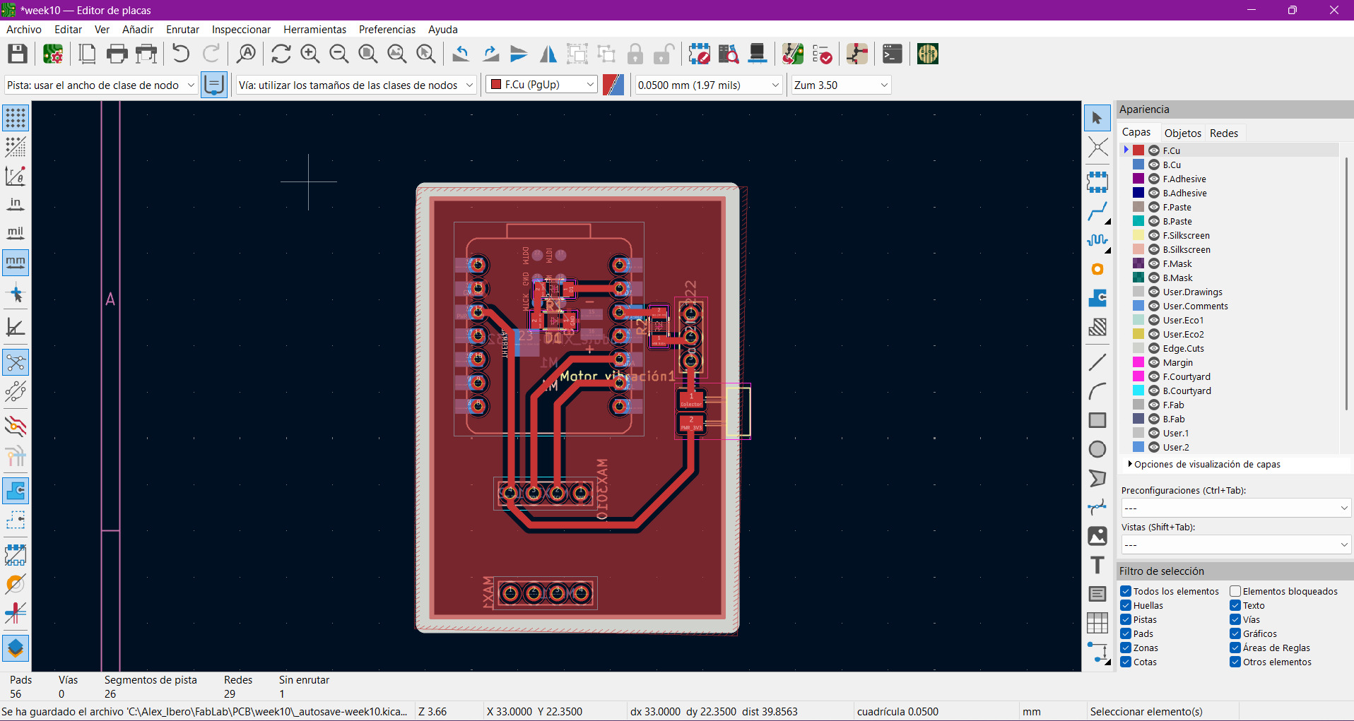
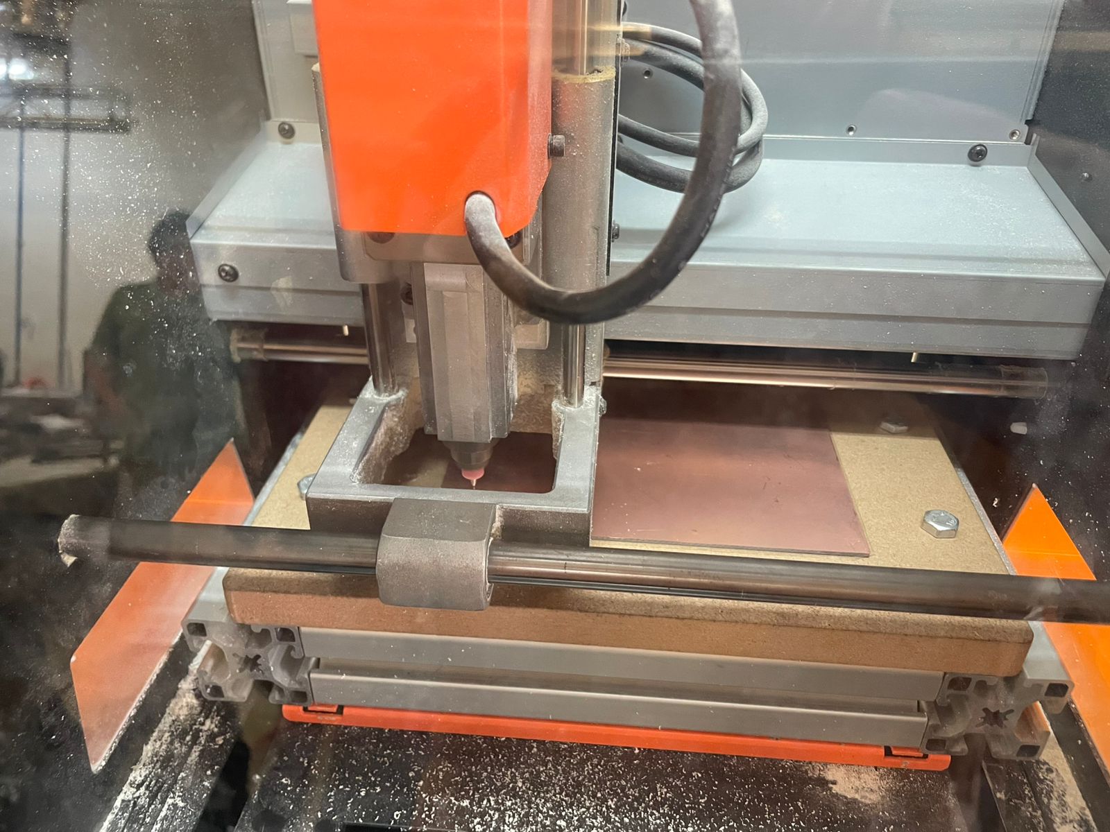
After validating the prototype, I assembled the PCB and tested the physical outputs directly from the board.
The LED and vibration motor successfully reacted to BPM changes detected by the sensor.
Here is a video showing the PCB working:
The code reads heart rate values from the MAX30102 sensor and calculates the BPM average.
During the first seconds, the system performs a calibration stage to establish a baseline heart rate.
If the BPM increases above the baseline threshold for several consecutive beats, the LED and vibration motor activate as alert outputs.
#include <Wire.h>
#include "MAX30105.h"
#include "heartRate.h"

MAX30105 particleSensor;

const int LED_PIN = D1;
const int MOTOR_PIN = D2;

const byte RATE_SIZE = 12;

byte rates[RATE_SIZE];

byte rateSpot = 0;

long lastBeat = 0;

float beatsPerMinute;

int beatAvg;

bool baseEstablecida = false;

int muestrasCalibracion = 0;

const int TOTAL_MUESTRAS_CAL = 20;

float sumaCalibracion = 0;

float pulsoBase = 0;

int altosConsecutivos = 0;

const int MINIMO_PULSOS_ALTO = 3;

bool alertaActiva = false;

void setup() {

  Serial.begin(115200);

  delay(1000);

  pinMode(LED_PIN, OUTPUT);

  pinMode(MOTOR_PIN, OUTPUT);

  digitalWrite(LED_PIN, LOW);

  digitalWrite(MOTOR_PIN, LOW);

  Wire.begin(22, 23);

  if (!particleSensor.begin(Wire, I2C_SPEED_FAST)) {

    Serial.println("MAX30102 no encontrado");

    while (1);

  }

  byte ledBrightness = 60;

  byte sampleAverage = 1;

  byte ledMode = 2;

  int sampleRate = 200;

  int pulseWidth = 411;

  int adcRange = 4096;

  particleSensor.setup(
    ledBrightness,
    sampleAverage,
    ledMode,
    sampleRate,
    pulseWidth,
    adcRange
  );

}

void loop() {

  long irValue = particleSensor.getIR();

  if (irValue < 50000) {

    digitalWrite(LED_PIN, LOW);

    digitalWrite(MOTOR_PIN, LOW);

    delay(500);

    return;

  }

  if (checkForBeat(irValue) == true) {

    long delta = millis() - lastBeat;

    lastBeat = millis();

    beatsPerMinute = 60 / (delta / 1000.0);

    if (beatsPerMinute < 140 &&
        beatsPerMinute > 40) {

      rates[rateSpot++] =
      (byte)beatsPerMinute;

      rateSpot %= RATE_SIZE;

      int sum = 0;

      for (byte x = 0; x < RATE_SIZE; x++) {

        sum += rates[x];

      }

      beatAvg = sum / RATE_SIZE;

      if (!baseEstablecida) {

        sumaCalibracion += beatsPerMinute;

        muestrasCalibracion++;

        if (muestrasCalibracion >=
            TOTAL_MUESTRAS_CAL) {

          pulsoBase =
          sumaCalibracion /
          TOTAL_MUESTRAS_CAL;

          baseEstablecida = true;

        }

      }

      else {

        float dif =
        beatAvg - pulsoBase;

        if (dif >= 4.0) {

          altosConsecutivos++;

          if (altosConsecutivos >=
              MINIMO_PULSOS_ALTO)

            alertaActiva = true;

        }

        else {

          altosConsecutivos = 0;

          alertaActiva = false;

        }

        if (alertaActiva) {

          digitalWrite(LED_PIN, HIGH);

          digitalWrite(MOTOR_PIN, HIGH);

        }

        else {

          digitalWrite(LED_PIN, LOW);

          digitalWrite(MOTOR_PIN, LOW);

        }

      }

    }

  }

}
Wrist movement still generates false BPM peaks during measurements.
Noisy readings can still affect the baseline BPM calculation.
The infrared readings are highly sensitive to pressure and micro-movements.
Some invalid BPM spikes still appear briefly before filtering.
Any instability in heartbeat detection immediately affects the actuators.
This assignment is directly related to my wearable final project because it integrates biometric sensing with physical feedback systems.
The long-term goal is to detect stress or BPM increases and provide calming responses through vibration patterns or visual indicators.
This week helped me better understand how to connect real-world outputs with biometric analysis in embedded systems.
Using vibration motors to communicate physiological states.
LEDs provide immediate status indication.
Improve filtering, miniaturization and wearable integration.