Main Sensors
MAX30102 and AD8232 heart monitor
Fab Academy 2026
Reading biometric data using heart rate sensors and integrating them with a custom microcontroller workflow.
MAX30102 and AD8232 heart monitor
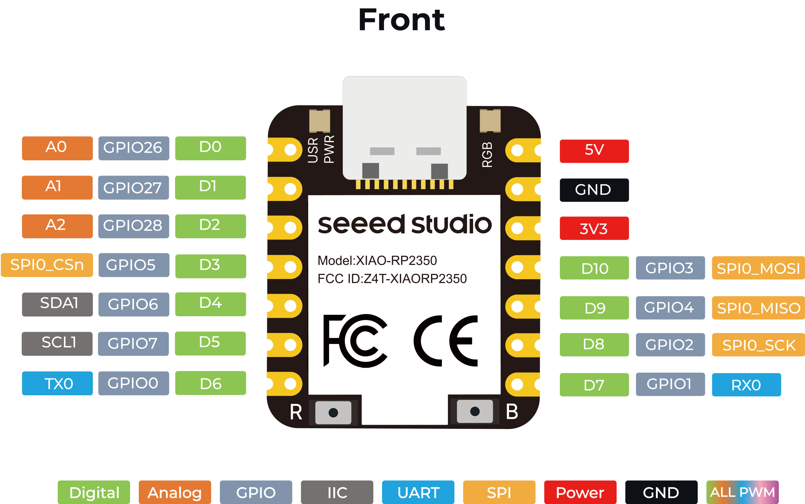
Seeed Studio XIAO RP2350
Read heart rate data and detect BPM changes for my final wearable project.
From the group assignment, I mainly reinforced concepts I had already learned, such as the difference between analog and digital signals.
I also reviewed how I2C communication works, including the roles of SDA and SCL.
One of the most useful parts was using an oscilloscope to visualize real sensor signals, which helped me confirm how these concepts apply in practice.
Overall, this assignment helped me solidify my understanding and gave me more confidence when working with sensors beyond just the code.
First, I wanted to use the MAX30102 because it is a heart rate and pulse oximeter sensor that could be very useful for my final project.
However, I had problems connecting it to my XIAO RP2350.
Even though the hardware connections were correct, the XIAO was unable to detect the sensor through I2C communication.
I will continue experimenting with this sensor because of its potential integration into my wearable device.
If the issue continues, I may need to switch either the sensor or the microcontroller.
After running into issues with the MAX30102, I decided to work with the AD8232 Heart Monitor instead.
This sensor is larger and probably will not fit into my final wearable design, but it still allowed me to learn how ECG signals are captured and processed.
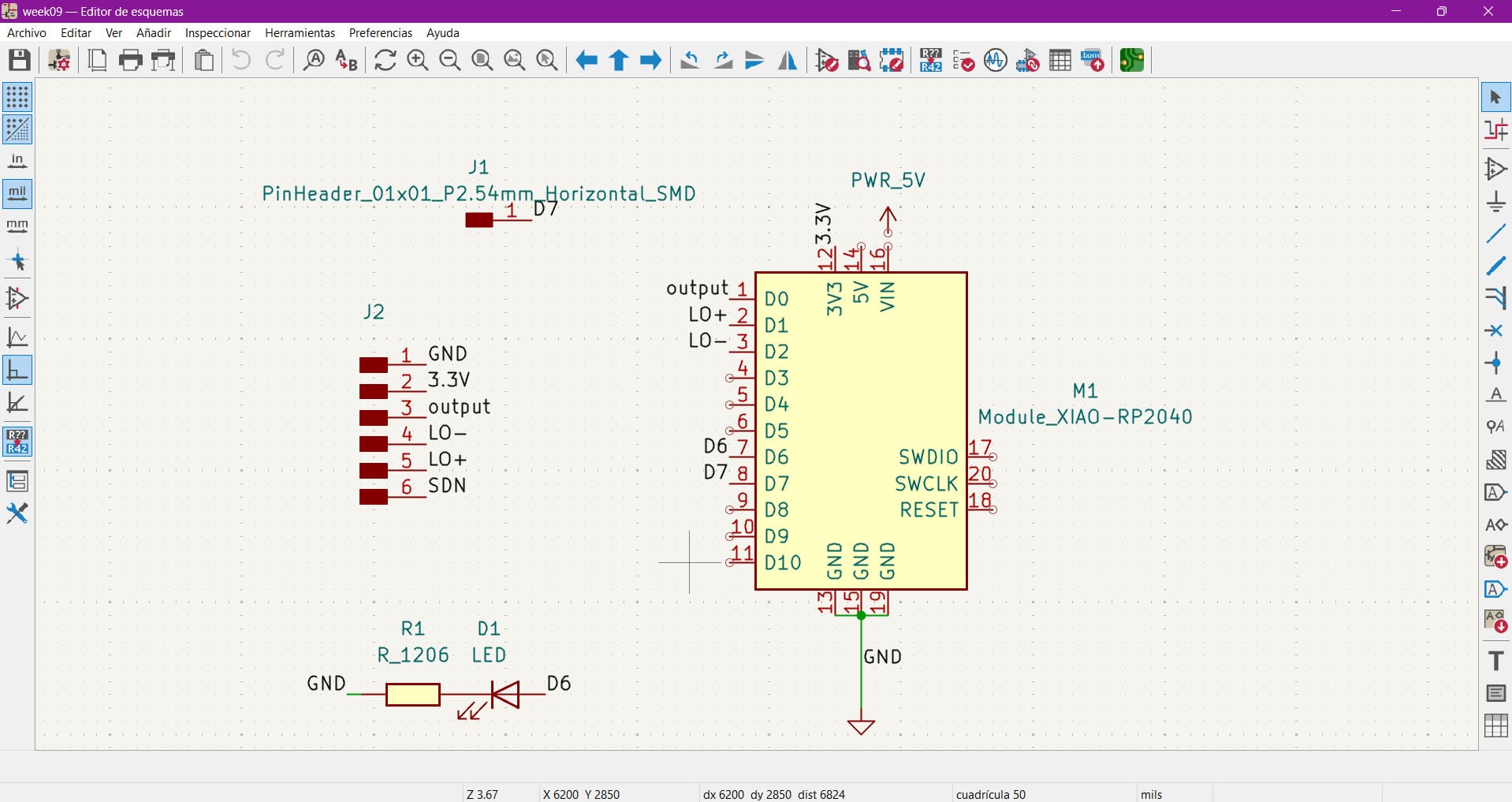
The first step was understanding the pinout and how to correctly wire the module.
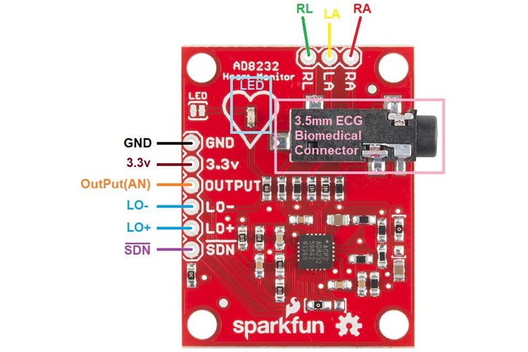
I connected GND to the XIAO ground pin, 3.3V to the 3.3V supply, and the signal output to D0.
The LO+ and LO- pins were connected to digital pins D1 and D2 to detect whether the electrodes were properly attached.
D0 reads the ECG waveform generated by the sensor.
LO+ and LO- detect if the electrodes become disconnected.
Detect heartbeats and monitor BPM changes in real time.
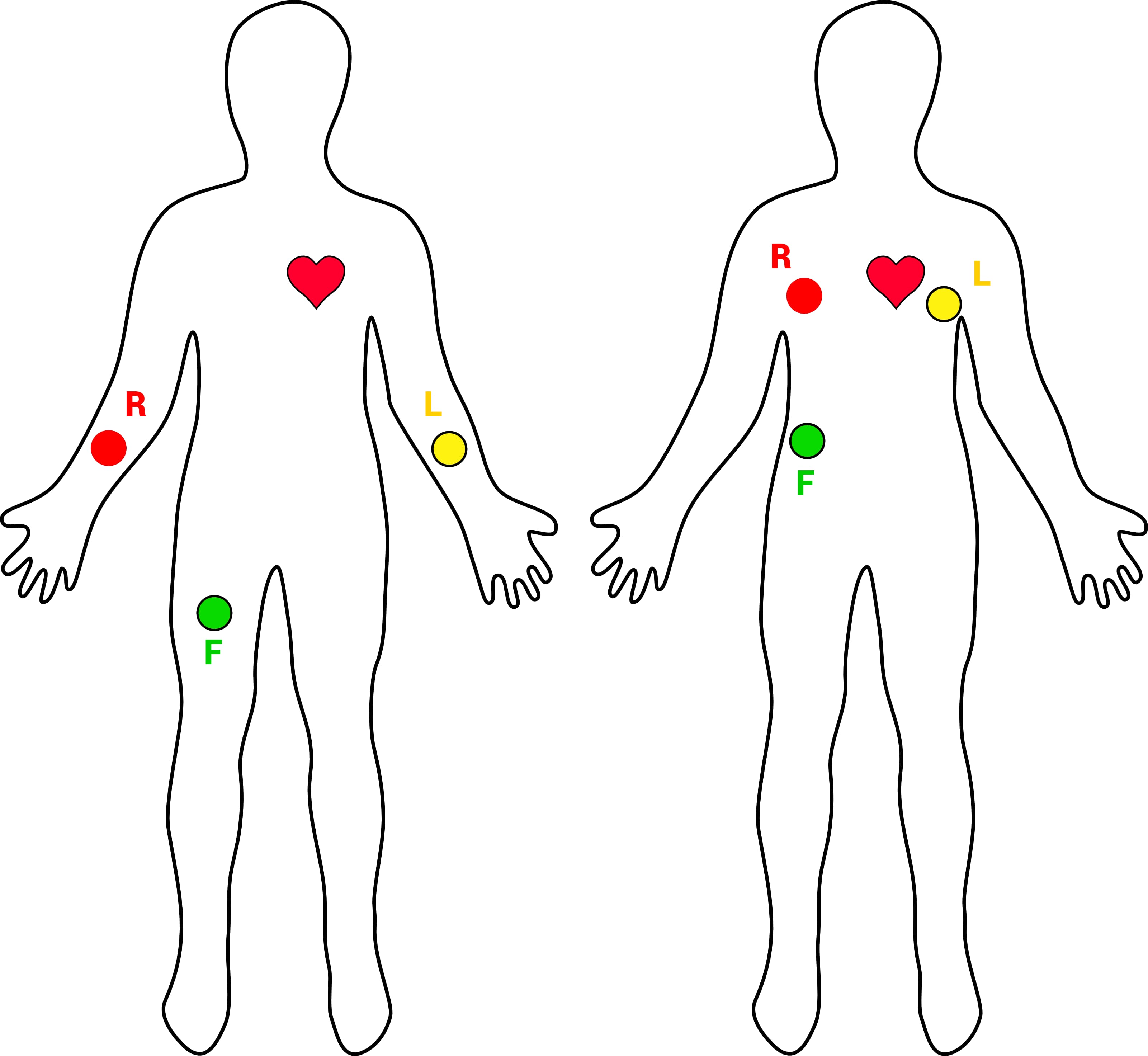
Before testing the circuit, it is important to correctly place the electrodes on the body.
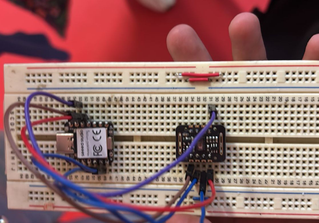
Once everything was connected, I tested the sensor using a protoboard and monitored the ECG signal through the Serial Monitor.
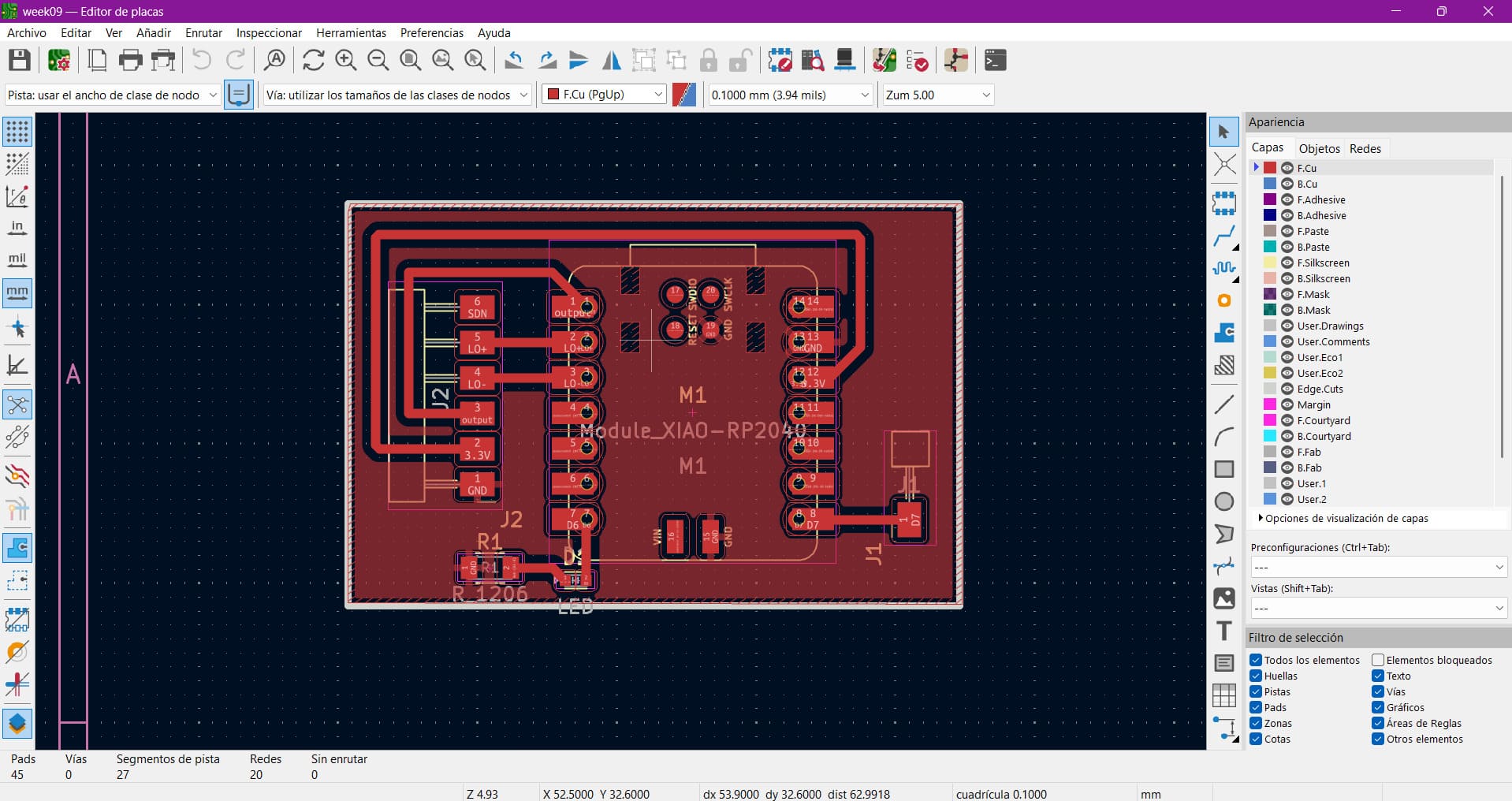
After validating the circuit on the protoboard, I created a simple PCB to make the setup more stable and compact.
Since I did not have pin headers available, I improvised by cutting, stripping and soldering jumper wires directly onto the PCB.
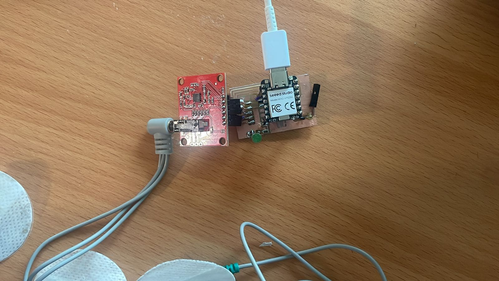
After assembling the PCB, I tested the system again to verify that the sensor and microcontroller still worked correctly.
The code reads the ECG signal, calculates BPM values and detects significant increases relative to a baseline heart rate.
If the BPM rises above the defined threshold, an LED starts blinking as an alert indicator.
#include <avr/io.h>

const int ECG_PIN = A0;
const int LO_MAS = 2;
const int LO_MENOS = 3;
const int LED_PIN = D6;

int threshold = 550;

bool lastBeat = false;

unsigned long lastBeatTime = 0;

int bpmArray[5] = {0,0,0,0,0};

int bpmIndex = 0;

int baselineBPM = 75;

int aumento = 10;

bool alerta = false;

unsigned long lastBlink = 0;

bool ledState = false;

void setup() {

  Serial.begin(115200);

  pinMode(LO_MAS, INPUT);

  pinMode(LO_MENOS, INPUT);

  pinMode(LED_PIN, OUTPUT);

}

void loop() {

  if (digitalRead(LO_MAS) == 1 ||
      digitalRead(LO_MENOS) == 1) {

    Serial.println("Electrodos desconectados");

    digitalWrite(LED_PIN, LOW);

    return;

  }

  int signal = analogRead(ECG_PIN);

  if (signal > threshold && !lastBeat) {

    unsigned long currentTime = millis();

    if (currentTime - lastBeatTime > 600) {

      if (lastBeatTime != 0) {

        int bpm =
        60000 / (currentTime - lastBeatTime);

        if (bpm > 40 && bpm < 100) {

          bpmArray[bpmIndex] = bpm;

          bpmIndex = (bpmIndex + 1) % 5;

          int sum = 0;

          for (int i = 0; i < 5; i++) {

            sum += bpmArray[i];

          }

          int avgBPM = sum / 5;

          Serial.print("BPM promedio: ");

          Serial.println(avgBPM);

          if (avgBPM > baselineBPM + aumento) {

            alerta = true;

            Serial.println("AUMENTO DETECTADO");

          }

          else {

            alerta = false;

          }

        }

      }

      lastBeatTime = currentTime;

    }

    lastBeat = true;

  }

  if (signal < threshold) {

    lastBeat = false;

  }

  if (alerta) {

    if (millis() - lastBlink > 500) {

      ledState = !ledState;

      digitalWrite(LED_PIN, ledState);

      lastBlink = millis();

    }

  }

  else {

    digitalWrite(LED_PIN, LOW);

  }

  delay(5);

}
Initially, I used the wrong LED pin definition, which caused the LED to not behave correctly.
BPM calculations were unstable until I corrected the timing logic and filtering process.
The LED stayed on because the BPM threshold logic was too sensitive before averaging the readings.
This assignment is directly related to my final wearable project because heart rate monitoring is one of the core functionalities I want to integrate.
The goal is to detect changes in BPM and eventually trigger calming feedback systems such as vibration or breathing guidance.
Even though the AD8232 is not ideal for the final version, this week helped me better understand biometric signal acquisition and sensor integration.
Learning how to read biometric signals from real sensors.
Implementing heartbeat detection and BPM calculations in real time.
Continue improving sensor accuracy and miniaturization for wearable integration.