Main Tool
VCarve and an Asia Robotica CNC Router.
Fab Academy 2026
Designing, machining and assembling a full-scale CNC furniture project using plywood and a CNC router.
VCarve and an Asia Robotica CNC Router.
12 mm plywood sheet.
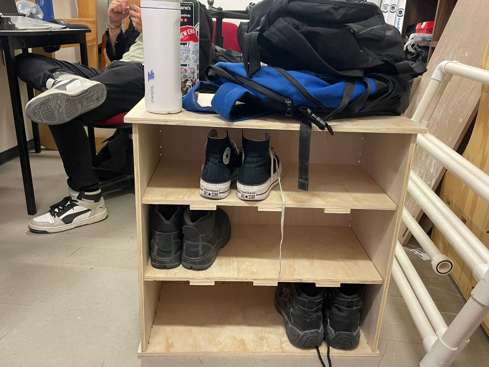
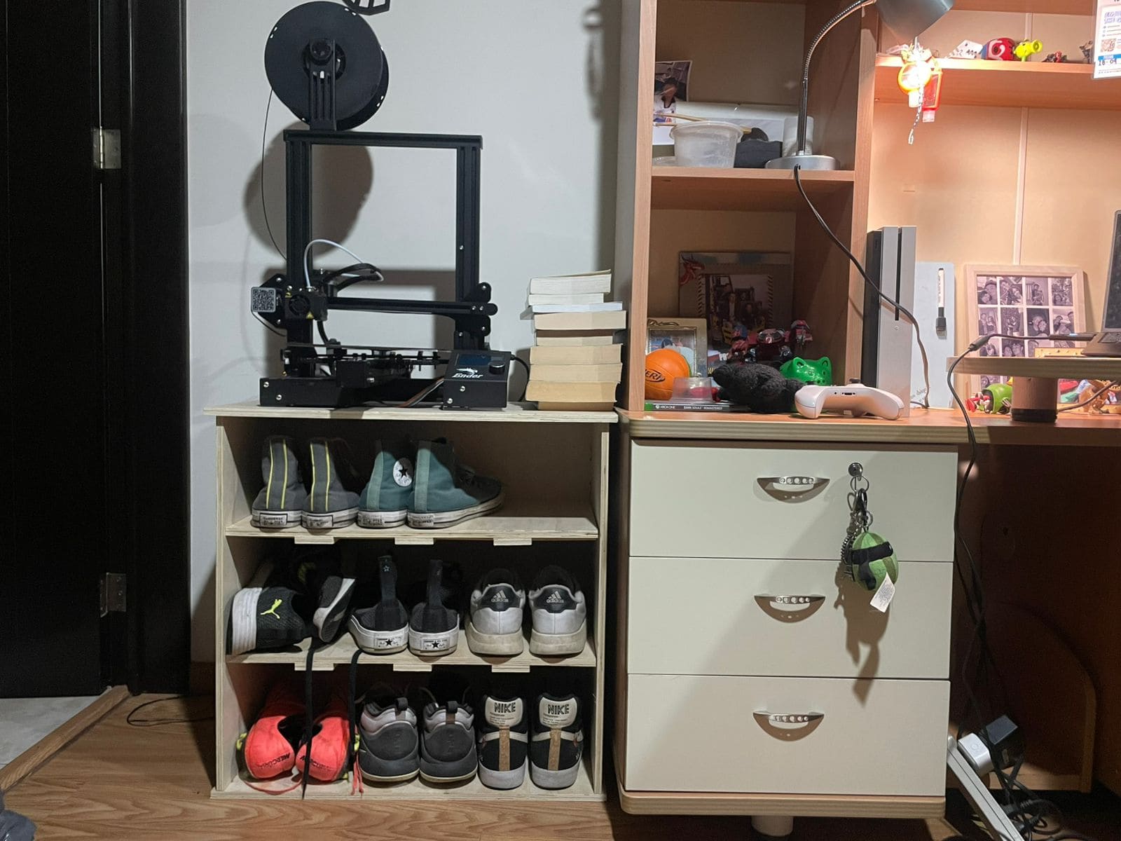
Build a functional full-scale furniture structure.
During the group assignment, I learned how to properly characterize and operate a CNC router.
One of the most important concepts was understanding the relationship between spindle speed, feed rate and chip load, since these parameters directly affect the cut quality and machining performance.
I also learned how important machine setup is before starting the machining process. This includes fixing the material correctly, selecting the right tool, defining the origin point and checking machine alignment.
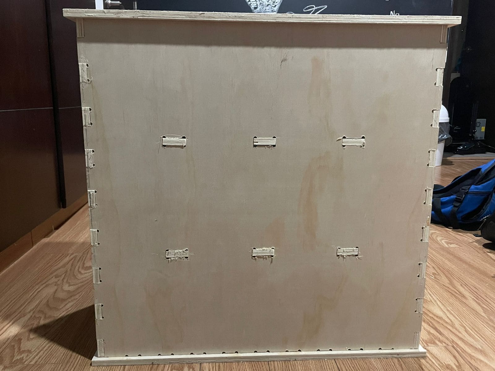
Another important lesson was learning about dogbone fillets. Since CNC router bits are circular, perfectly square internal corners cannot be produced directly, so these reliefs help parts fit together properly during assembly.
Safety was also a critical part of the assignment. CNC routers should never be left unattended while operating, and using safety glasses, lab coats and hearing protection is extremely important.
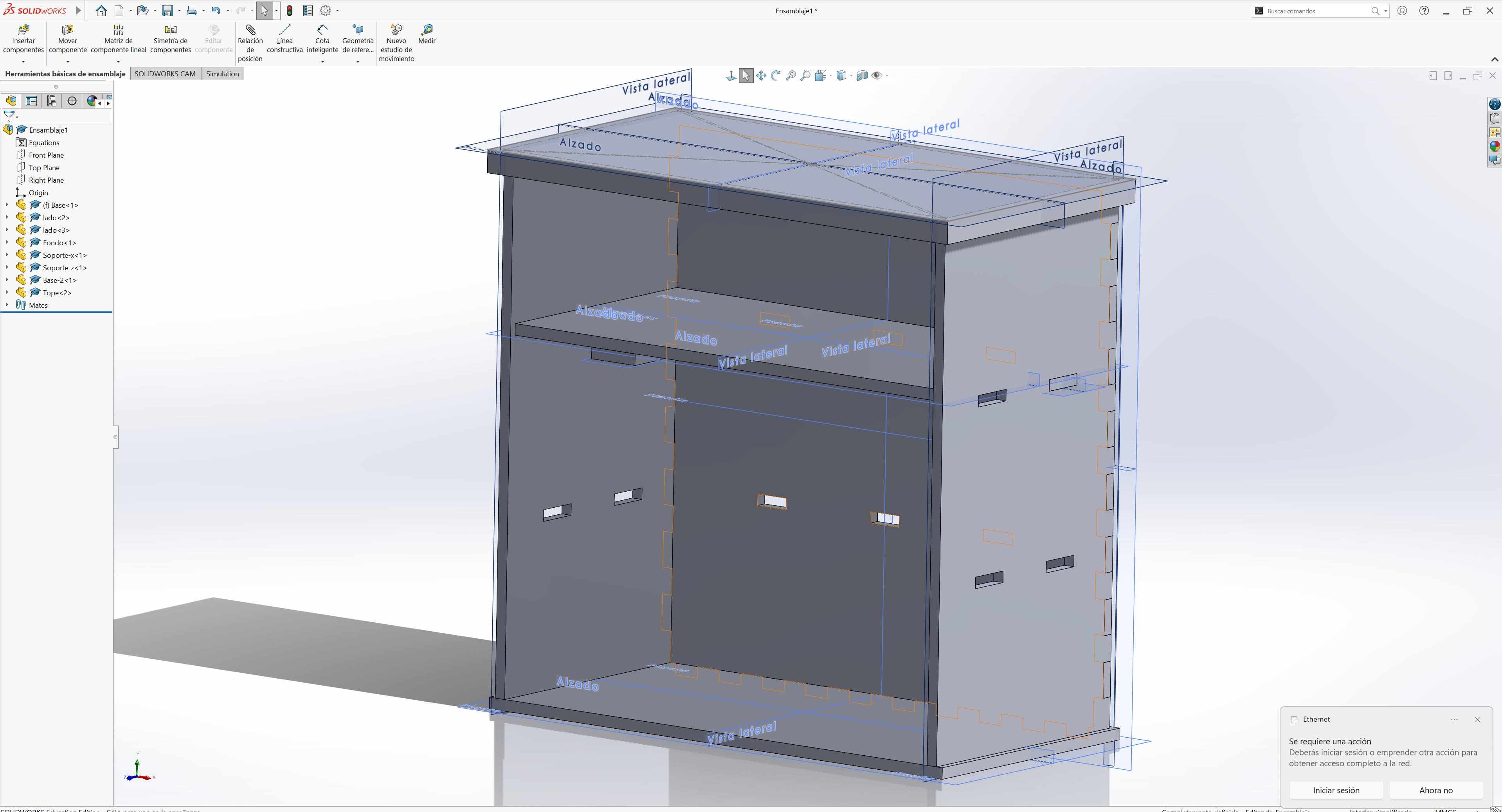
Group Assignment – Computer-Controlled MachiningThe first step was designing all the pieces in SolidWorks.
I modeled every part individually and later created an assembly to verify that all the joints and dimensions fit correctly.
To validate the design, I used the Interference Detection tool in SolidWorks:
Tools → Evaluate → Interference Detection
This allowed me to identify collisions and overlaps between components before manufacturing the project.
The slots and joints were designed using the thickness of the plywood board as reference, which was 12 mm.
Once the design was complete, I exported all the parts as DXF files and imported them into VCarve to prepare the machining process.
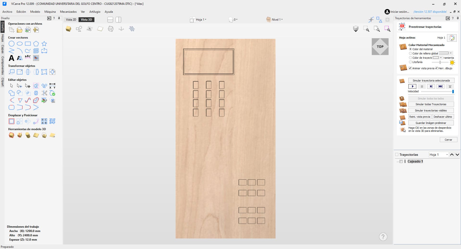
In VCarve, the first step was configuring the material dimensions, including width, height and thickness.
Then I imported the vectors using:
File → Import → Import Vectors / Bitmap
While arranging the pieces, I left enough free space near the edges to avoid interference with the CNC clamps.
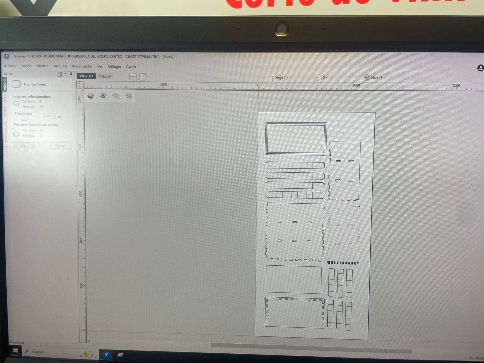
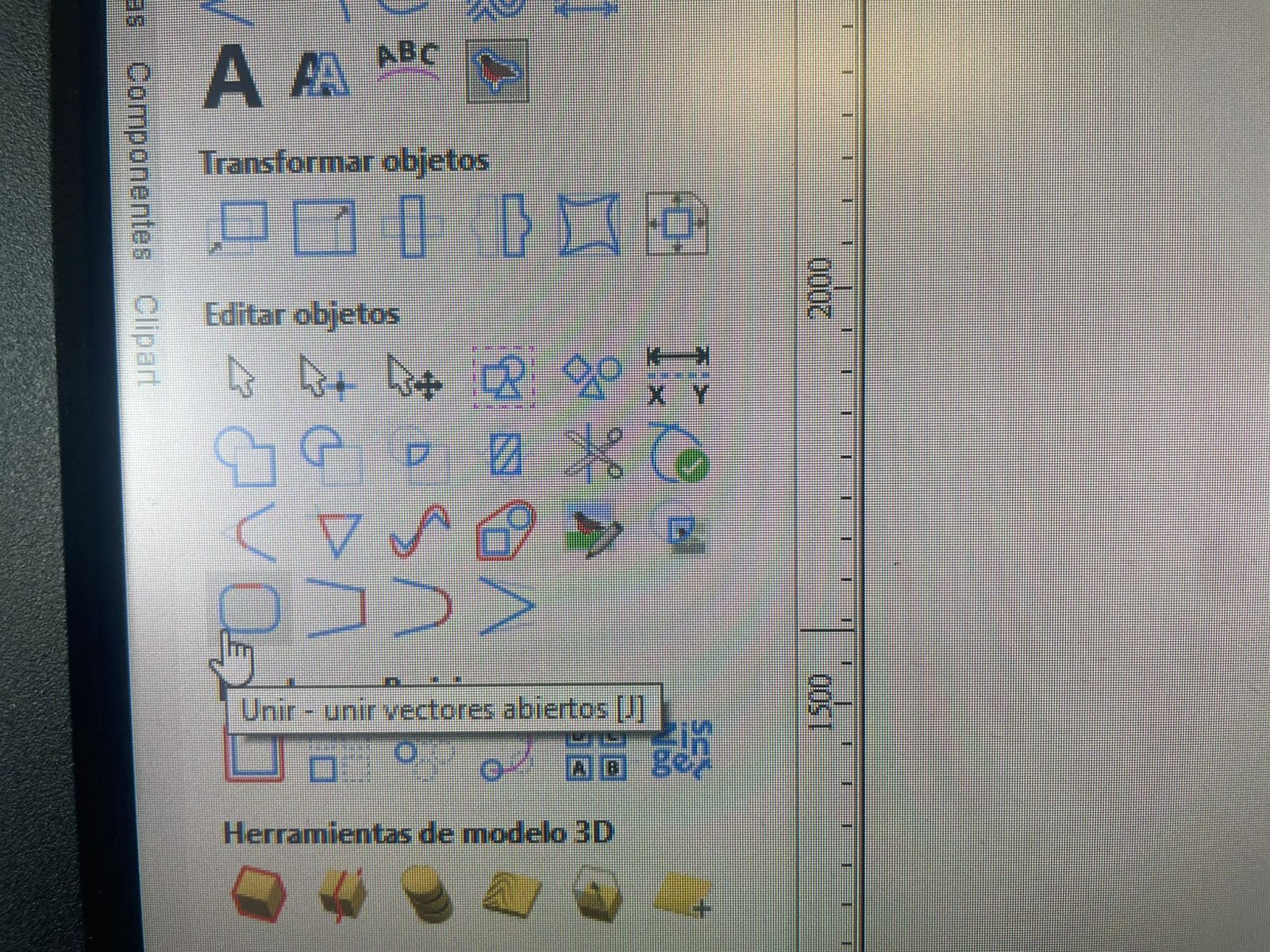
I also used the Join Vectors tool to merge disconnected lines and ensure continuous cutting paths.
After preparing the vectors, I configured the machining operations.
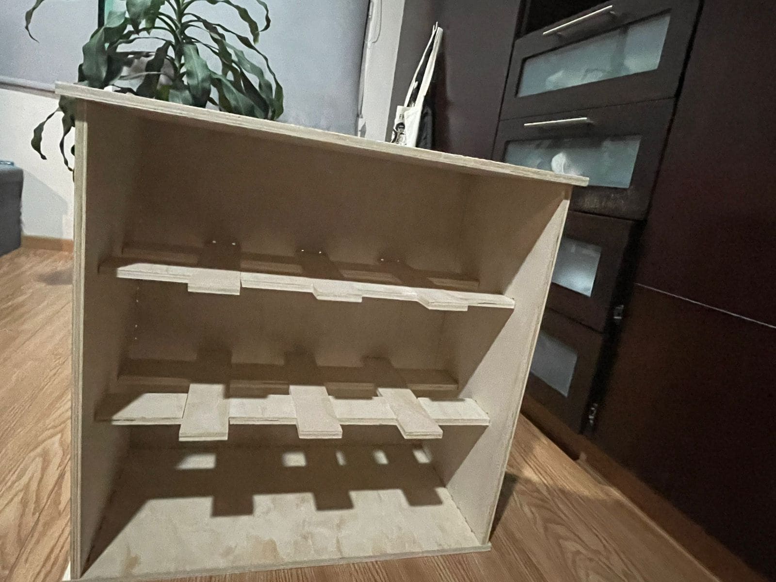
First, I created pocket toolpaths to remove small amounts of material and generate recessed areas that help certain joints fit together correctly.
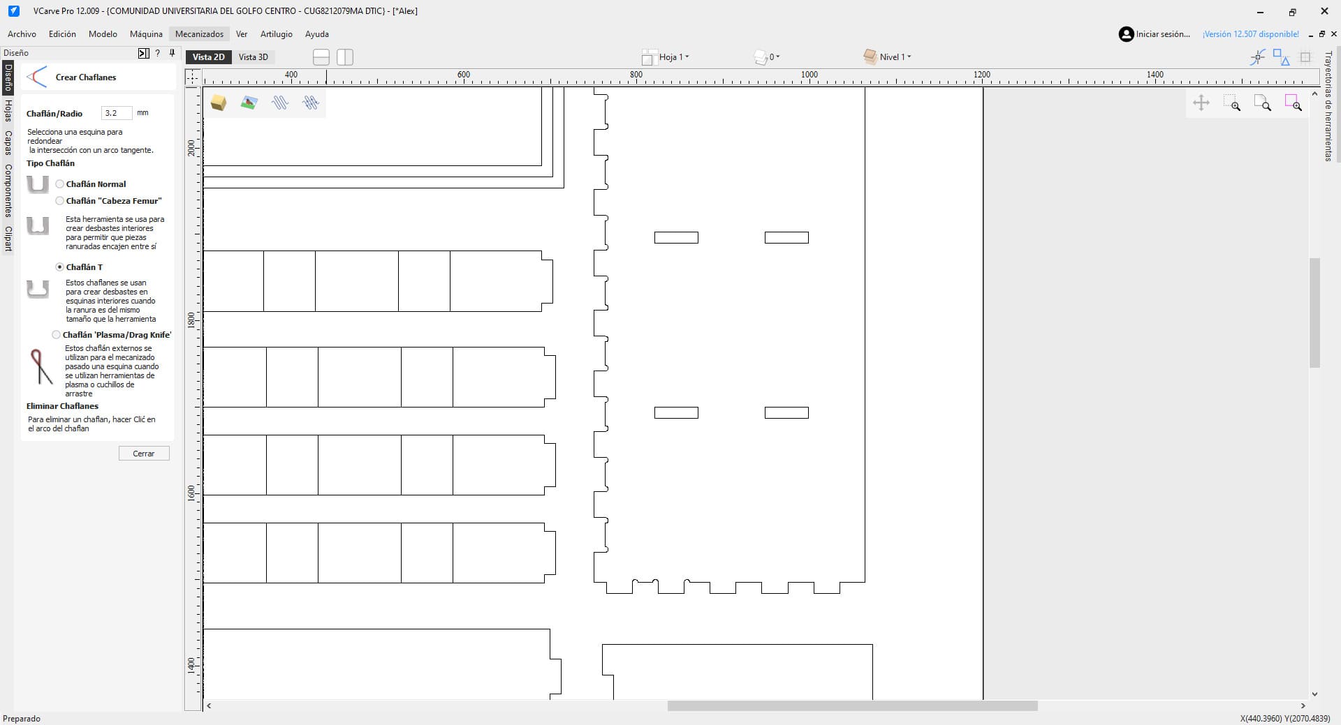
Then I configured the profile cuts used to completely cut through the plywood sheet.
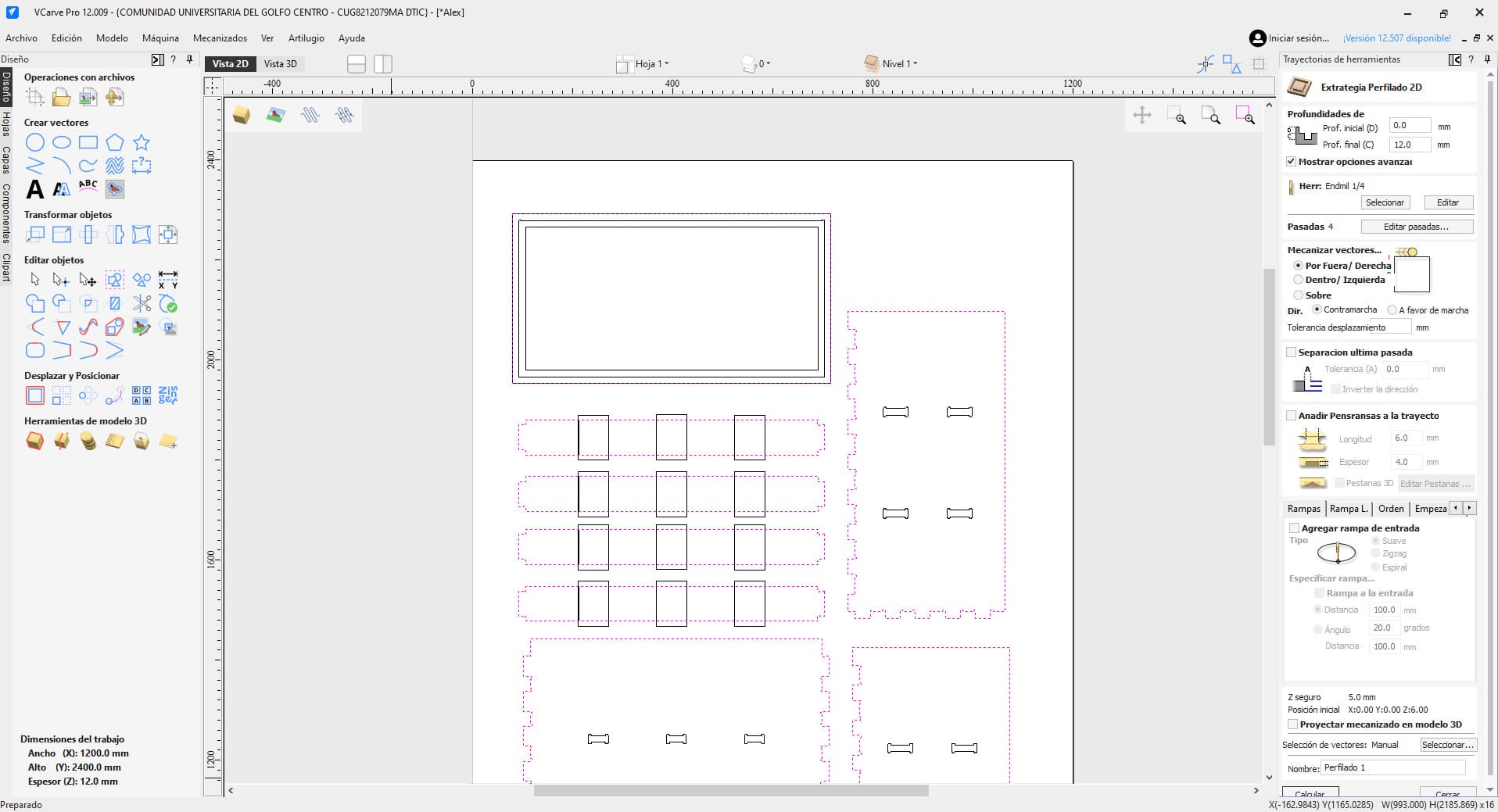
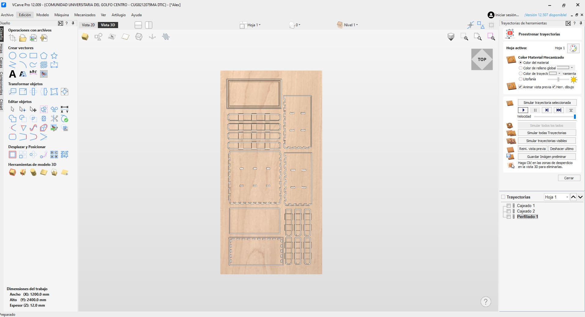
This was the final toolpath configuration:
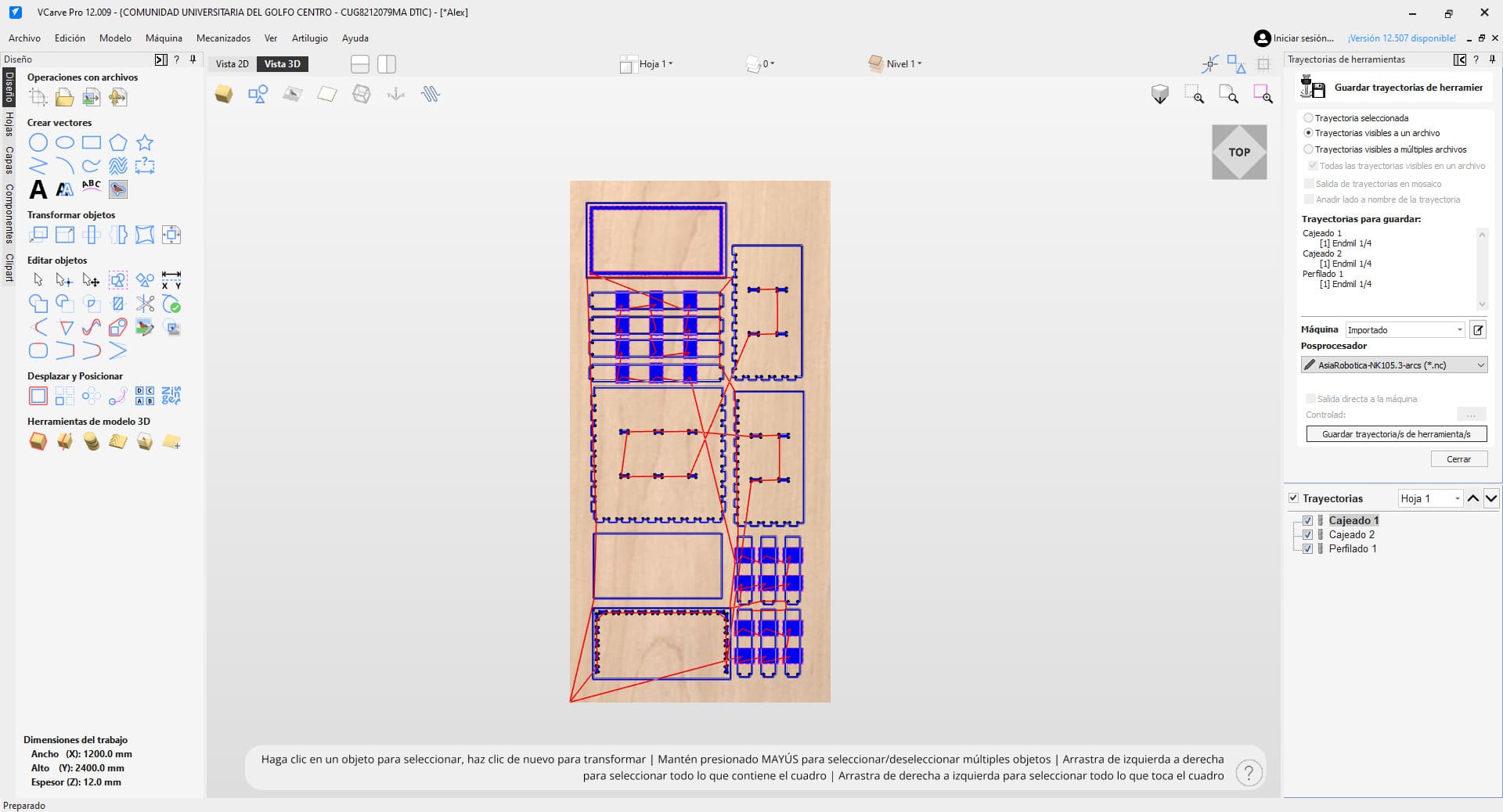
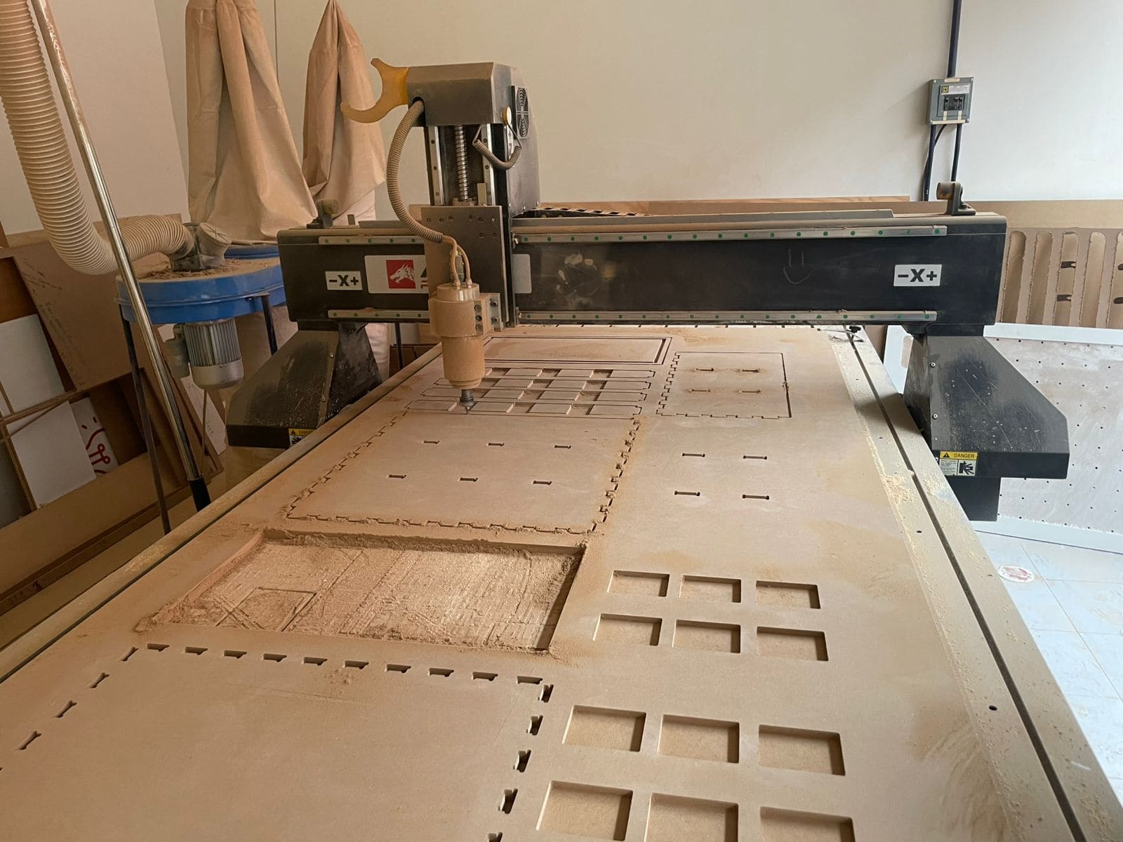
Once the toolpaths were ready, I moved to the Asia Robotica CNC router to begin machining.
Before cutting, I saved the file locally on the machine so the process could be resumed if needed.
I then set the origin point at the bottom-left corner of the material and carefully adjusted the Z height so the bit barely touched the surface.
The machine initially started cutting at 40% speed, and I gradually increased it to around 90% while monitoring chip accumulation and temperature.
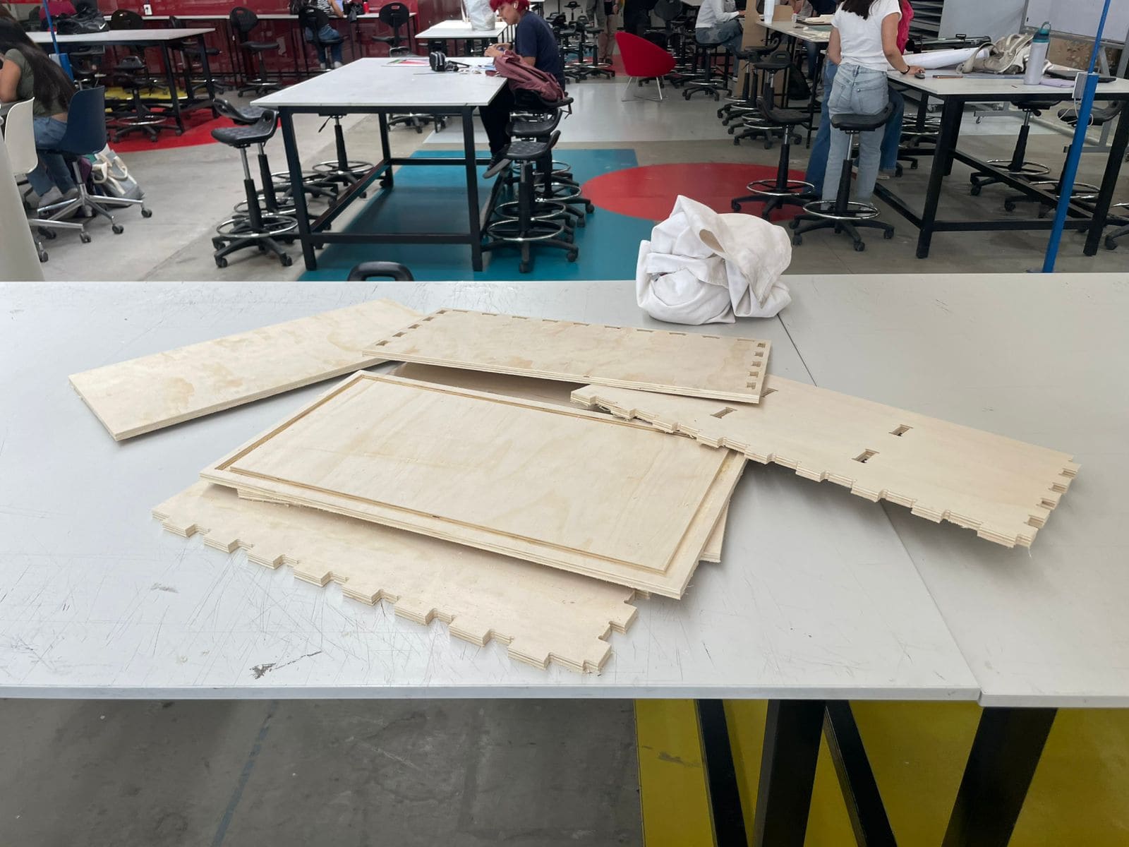
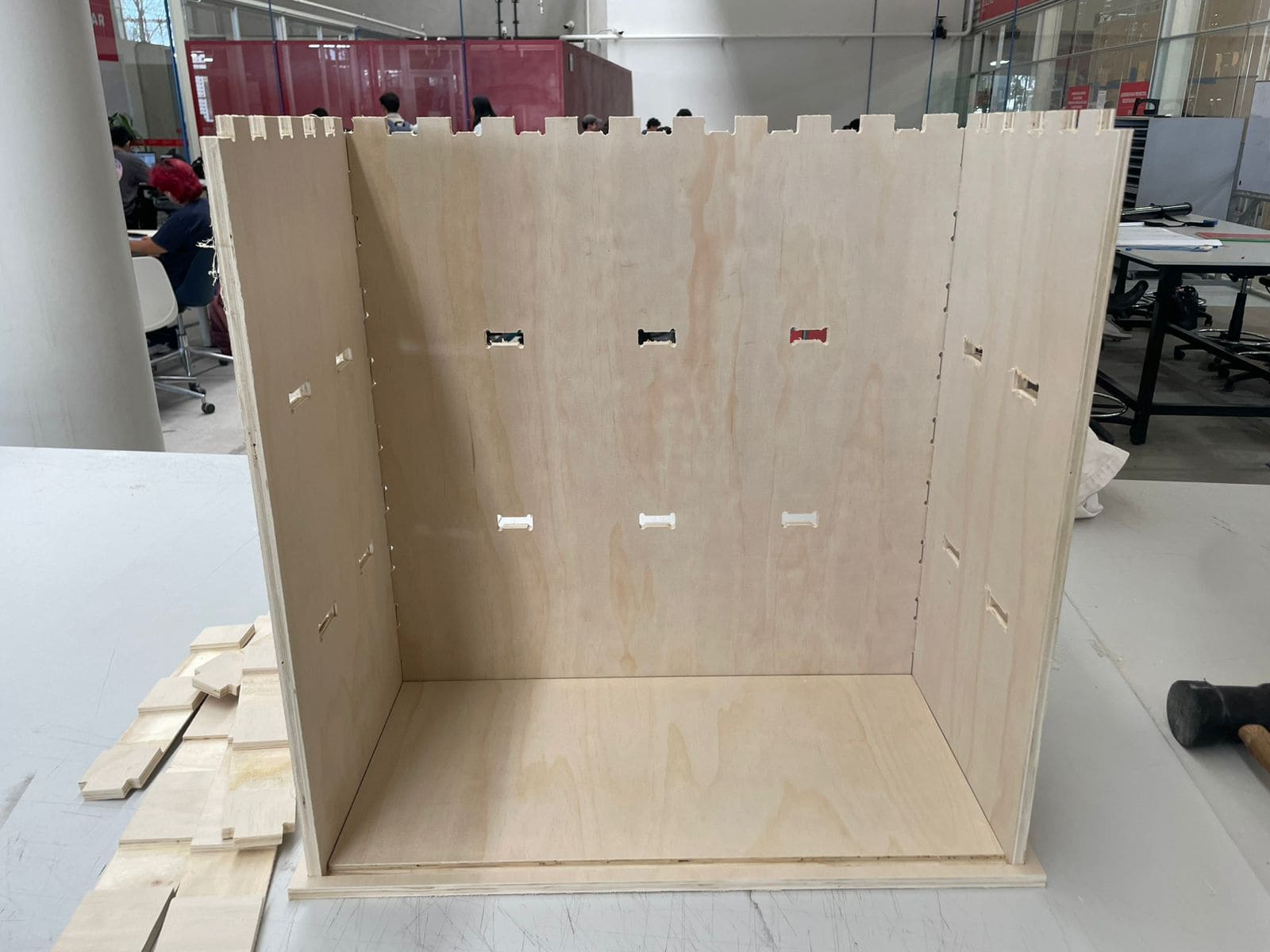
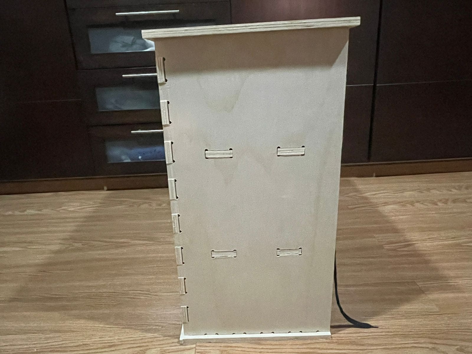
After machining, I removed all the pieces from the plywood sheet and prepared them for assembly.
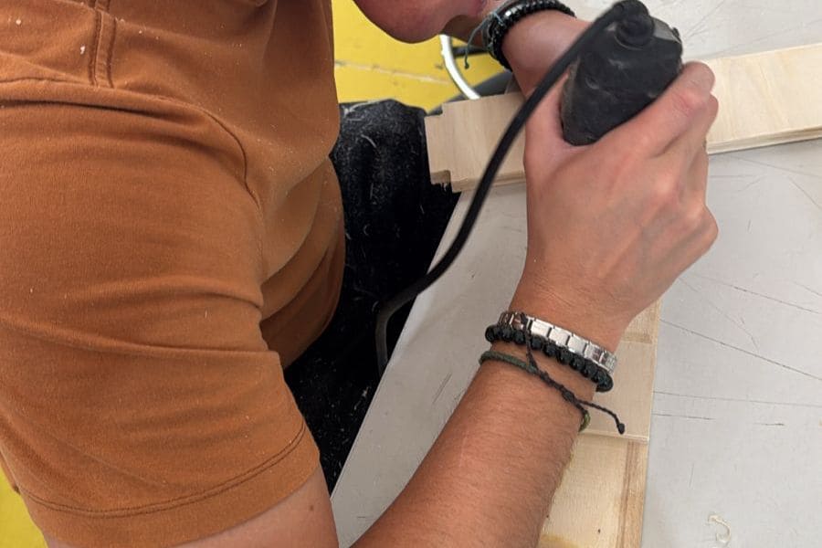
Some joints were too tight, so I used a Dremel tool to sand the edges until the parts fit correctly.
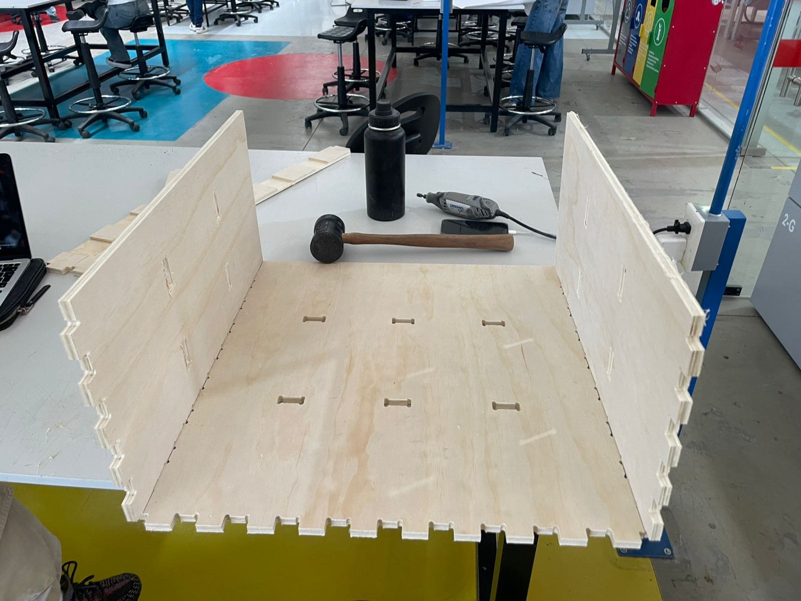
I also used a rubber mallet to gently assemble the structure without damaging the material.
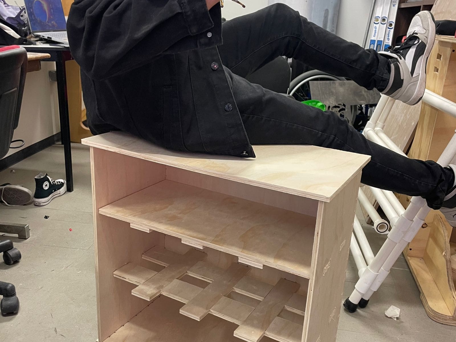
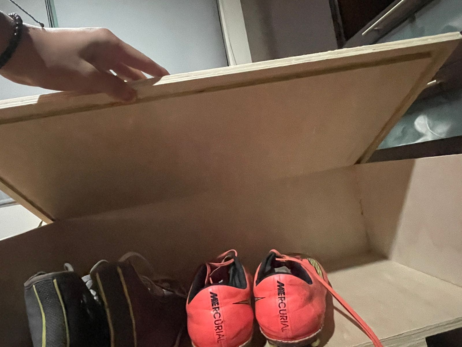
Once all the adjustments were complete, I assembled the furniture and tested its stability.
I designed the slots exactly at 12 mm without considering machining tolerances, so the joints ended up being too tight.
I solved the issue by sanding the joints with a Dremel tool.
Initially I configured the final cut depth at exactly 12 mm, which was not enough to fully cut through the material.
I corrected the issue by increasing the cut depth to 13 mm.
Tabs help keep the pieces attached to the material during machining and prevent dangerous movement.
Always leave enough free space near the board edges so the CNC clamps do not interfere with the toolpath.
Always double-check cut depth, feed rate and machining order before starting the CNC process.