Machines
CO₂ Laser Cutter and Vinyl Cutter.
Fab Academy 2026
Learning laser cutting, kerf compensation, vinyl cutting and parametric design workflows.
CO₂ Laser Cutter and Vinyl Cutter.
SolidWorks, Inkscape and laser cutting software.
Parametric design, kerf compensation and vector cutting.
In this group assignment, we characterized the laser cutting machines available at FabLab Puebla.
We reviewed the lab safety procedures, analyzed the specifications of the CO₂ laser cutters, and tested different materials such as wood, MDF and acrylic.
We evaluated parameters including power, speed, focus and kerf to understand how they influence cutting quality and precision.
This process allowed us to determine optimal machine settings for future projects and ensured safe and accurate operation.
Group Assignment – Laser Cutter CharacterizationI learned how to calibrate the laser height, how to safely turn the machine on and off, how to properly use the software and how the machine functions internally.
Since we were in the month of love, I decided to design a 3D heart model as a gift for my girlfriend.
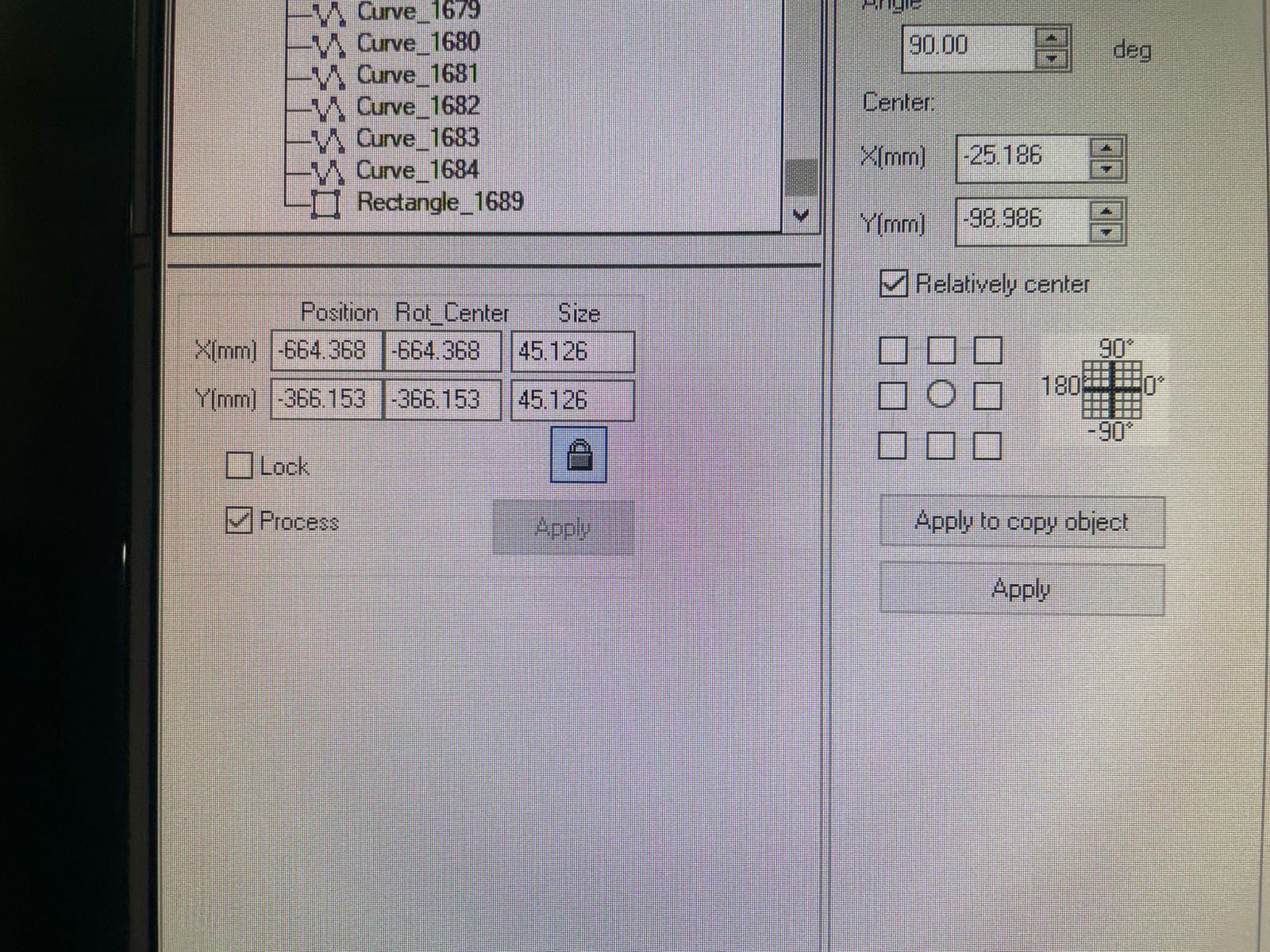
To make the model parametric, I used the Equations tool in SolidWorks.
This tool allows dimensions and formulas to automatically update the model when changing parameters.
Used to control dimensions and proportions automatically.
Slot dimensions were adjusted to compensate for laser material removal.
The heart proportions remained consistent when resizing the design.
I created global variables for:
The Equations tool can be found in:
Tools → Equations
I also created an assembly in SolidWorks to verify that all pieces fit correctly before manufacturing.
After finalizing the design, I exported the files and sent them to the laser cutting machine.
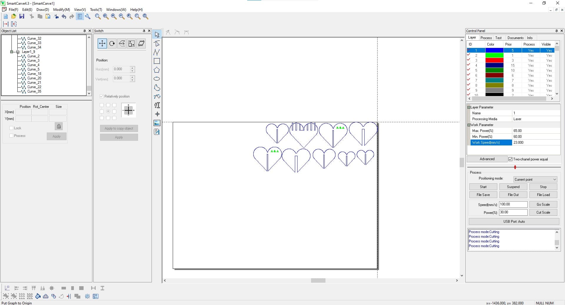
2.5 mm MDF
+0.2 mm
18 mm/s
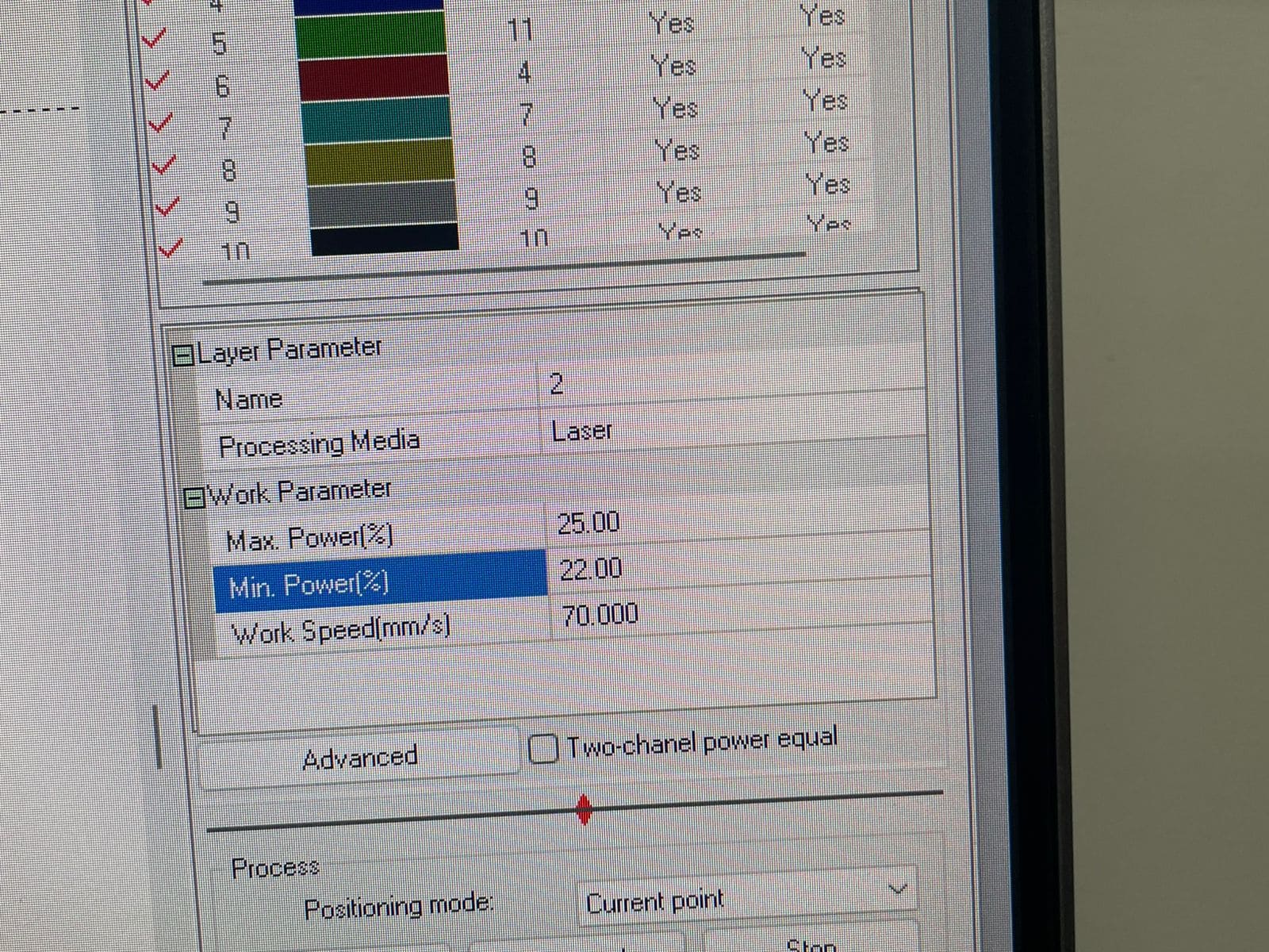
Max: 65% / Min: 55%
The laser cutter uses both maximum and minimum power values to maintain energy consistency during acceleration and deceleration.
The minimum power prevents incomplete cuts in corners and curves where the machine slows down.
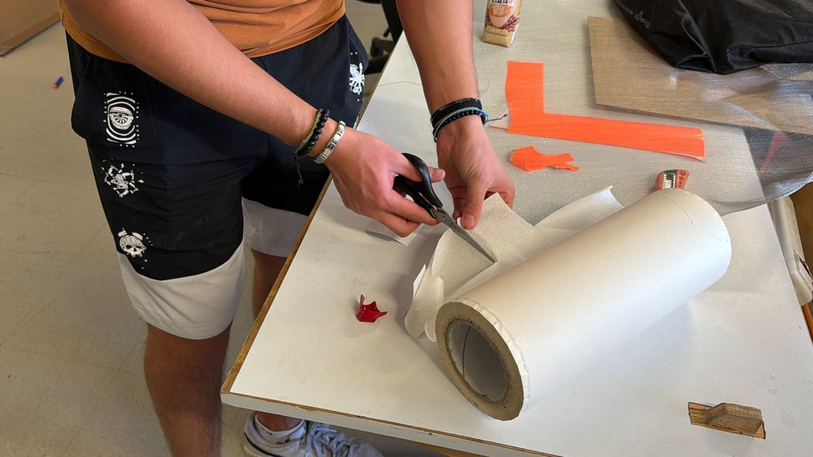
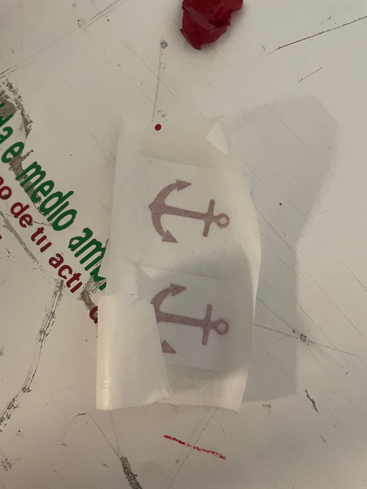
For the vinyl cutter assignment, I used an anchor design inspired by the name of my final project, “Ancora,” which means anchor in Latin.
I used Inkscape to vectorize the image and exported it as an SVG file to prepare it for the vinyl cutting software.
Inkscape Official Website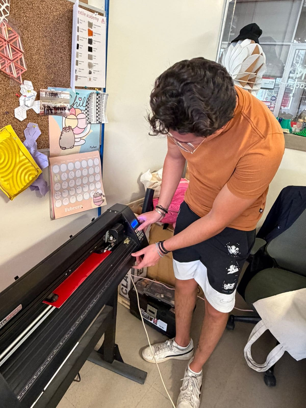
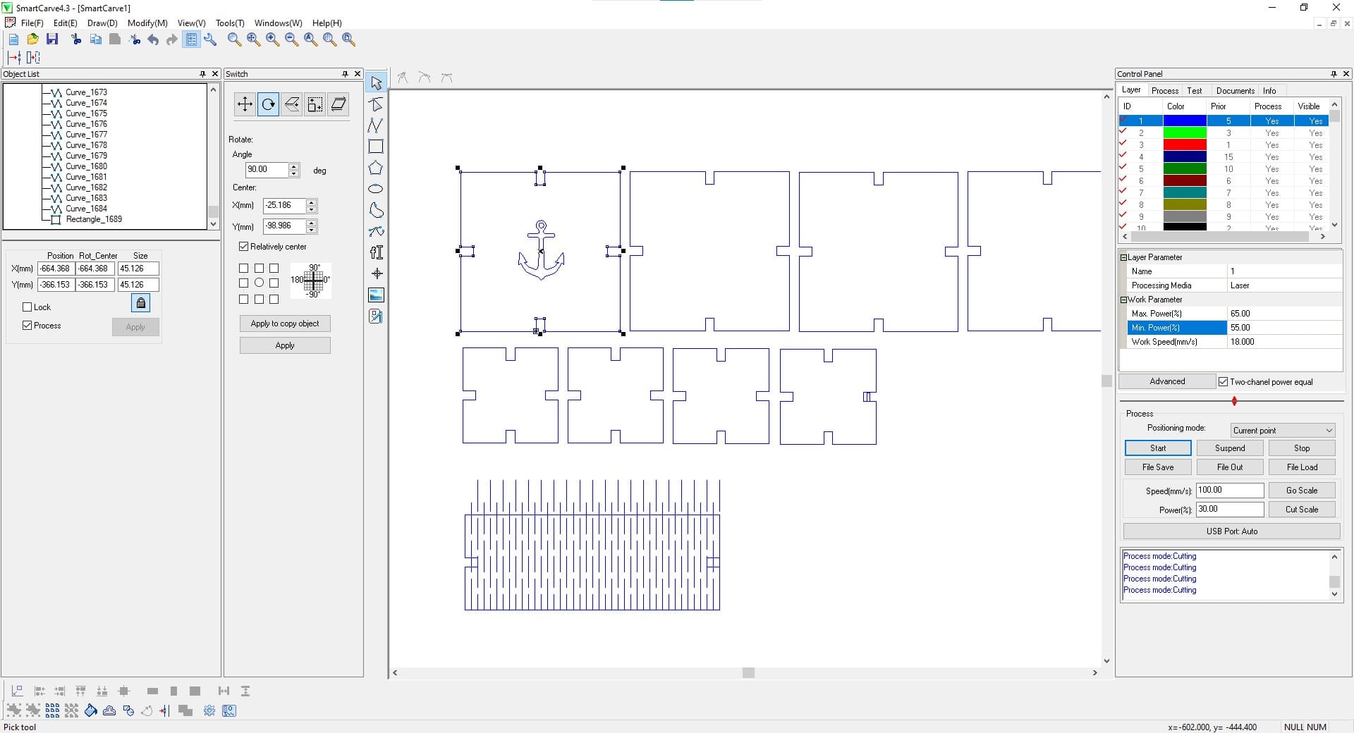
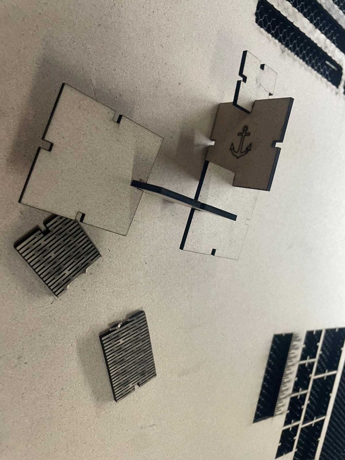
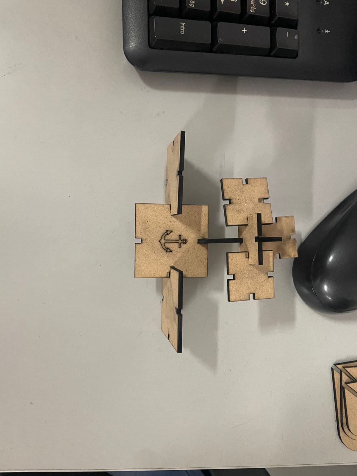
I created a parametric construction kit that allows multiple assembly configurations.
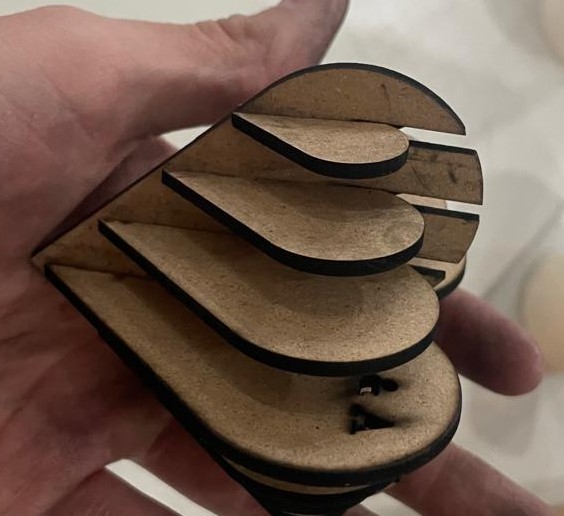
I tried creating non-flat flexible elements by designing a bendable structure.
Initially I placed the lines horizontally instead of vertically, so the part bent incorrectly.
Then I corrected the direction of the lines, but I left too little spacing between them.
Because the spacing was too small, the material broke when I tried bending it.
For the engraving assignment, I reused the SVG vectors from the vinyl cutter and imported them into SolidWorks.
Then I configured engraving parameters in the laser cutting software.
There was a scaling issue in SolidWorks, so I manually adjusted the size inside the laser cutting software.
Final engraved and assembled project: