

12. Mechanical Design and Machine Design
The focus of this week is to design a machine which shows an understanding of mechanisms, actuation, automation, and application. Working in a group with Emil, a Fab Learning student who also works at Moonlighter FabLab, our project became a chance for us to expand upon our previous projects.
Tasks and Responsibilities
- Emil: Initial Concept and Lesson Plan
- Emil: Initial Gear Calculations and Modeling
- Emil: Draft 3D Printing
- Jadayne: Design Development
- Jadayne: 3D Modeling
- Jadayne: 3D Printing
- Jadayne: PCB Design and Code
- Emil and Jadayne: Assembly and Testing
- Jadayne: Documentation
Part 1: Mechanical Design
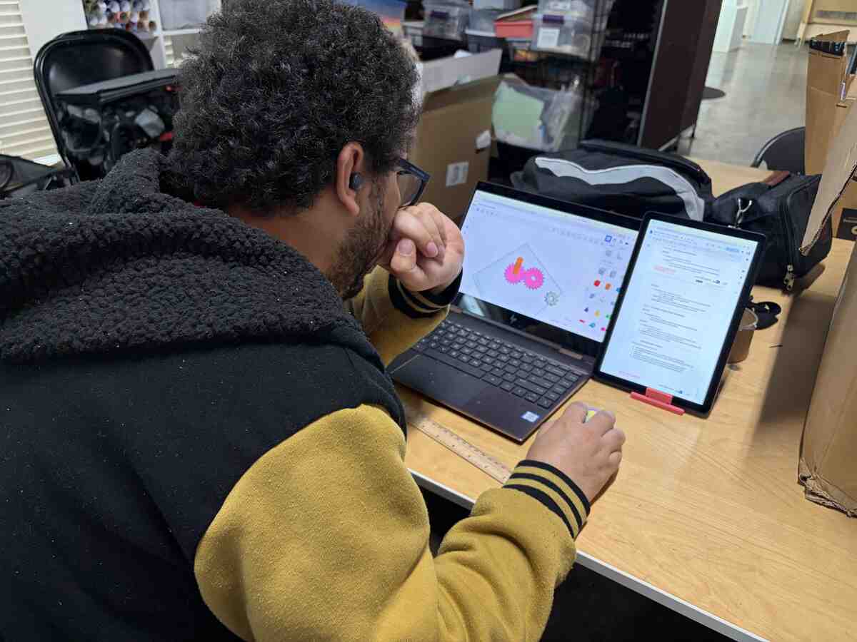
To start, Emil designed the gears for a time tracking mechanism. This was a part of one of his lesson plans for elementary school students. He calculated the gear ratios and the relationships to track seconds and minutes. He then used Tinkercad to model the prototype for his design.
.JPG)
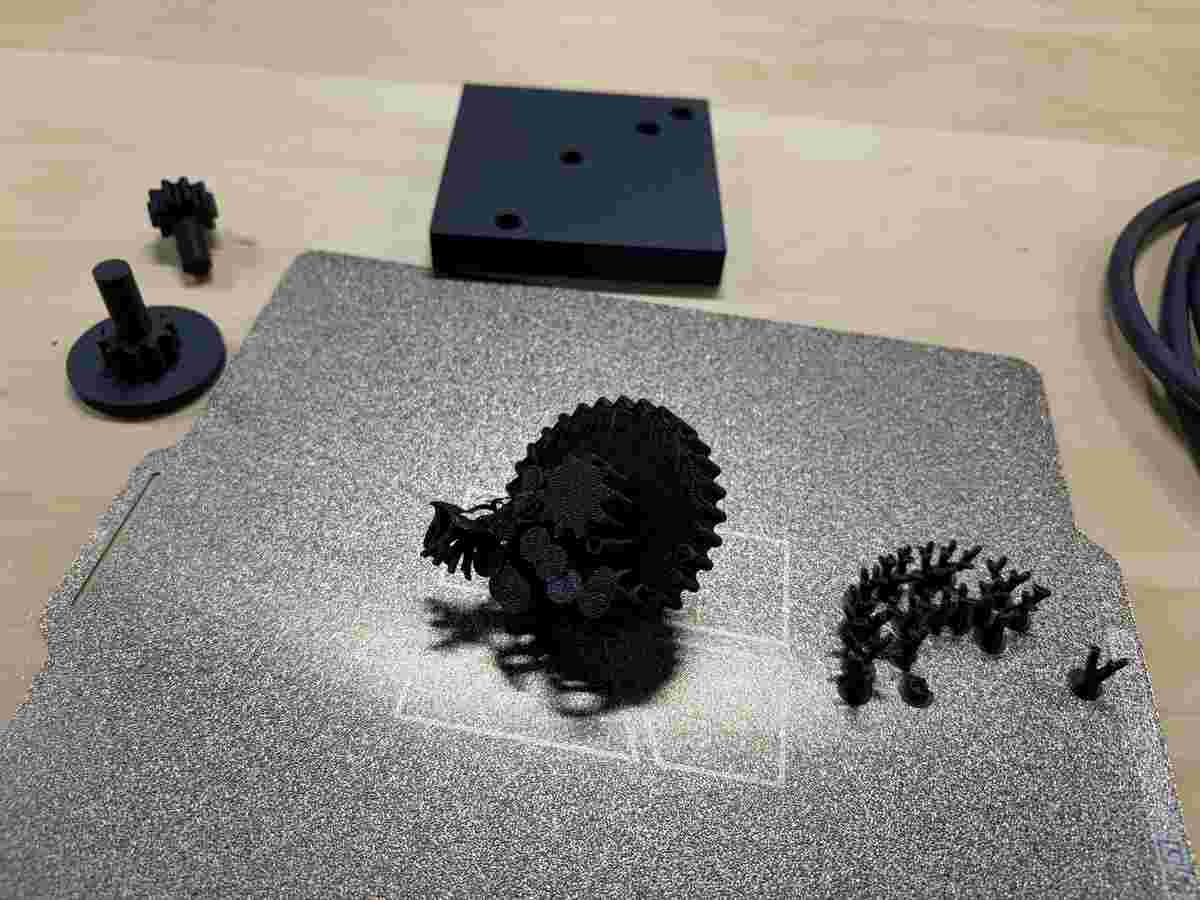
This is the 3D printed prototype he produced.
Gear Redesign
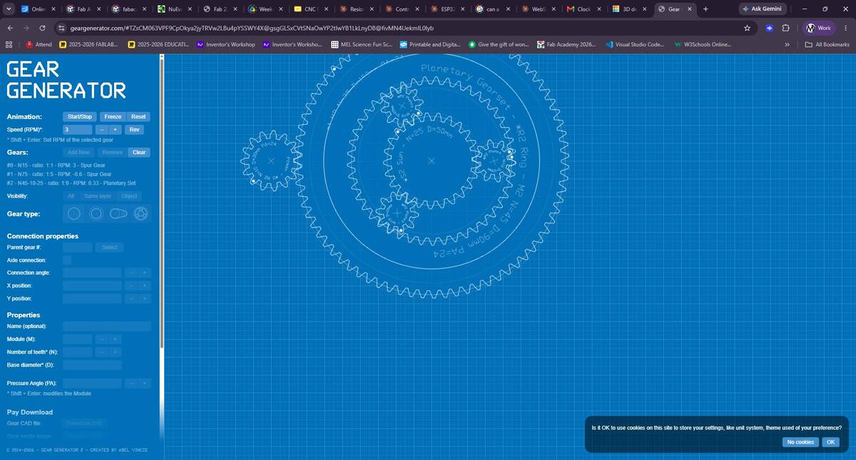
I decided to explore gear assemblies further to see if I could design a more integrated system for his concept. This brought me to a gear generator website that simulates gear assemblis and allows you to modify them. Unfortunately, this site was not free, so I used the simulation as a reference as I sought out other resources.

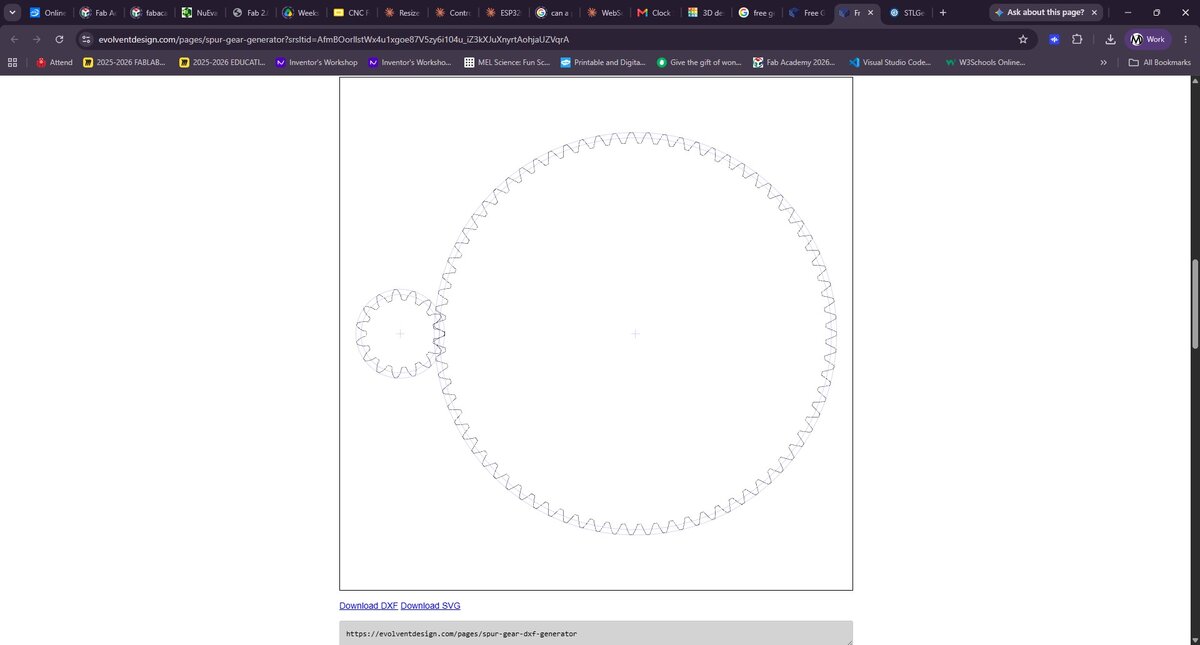
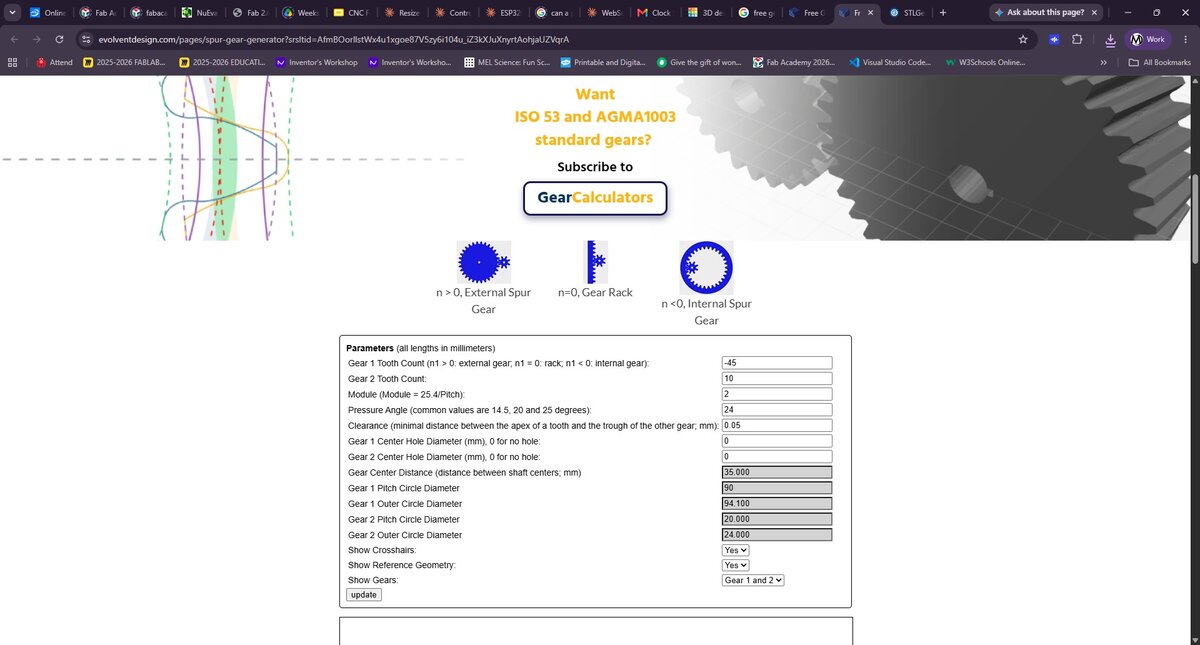
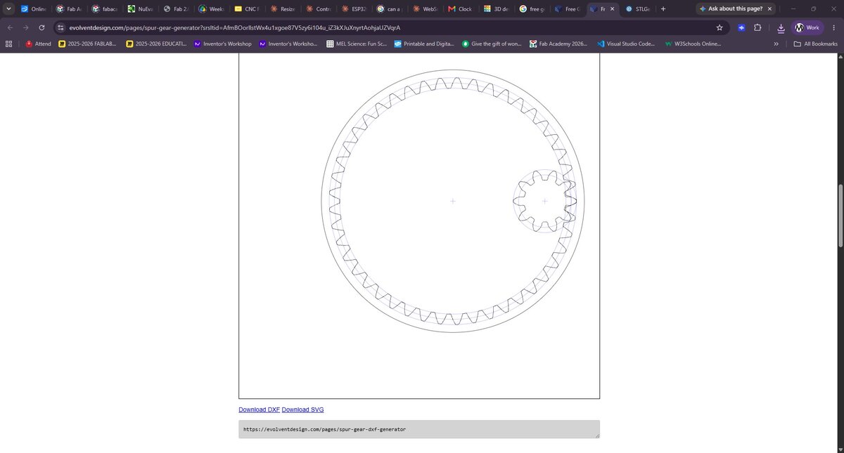
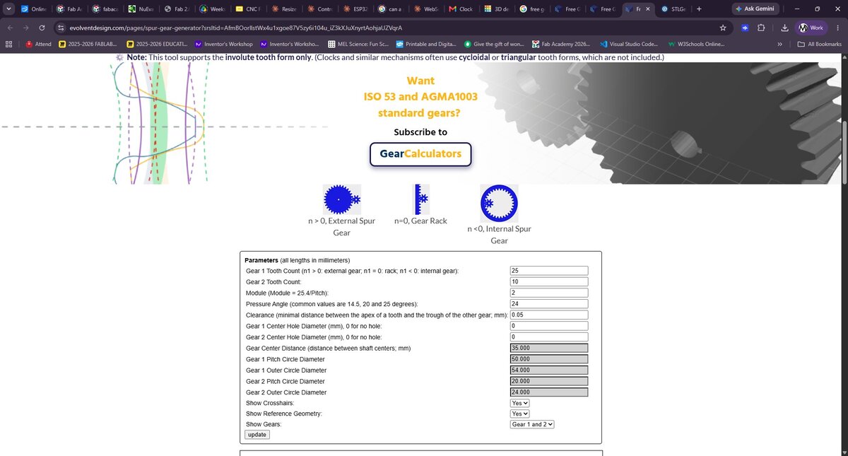
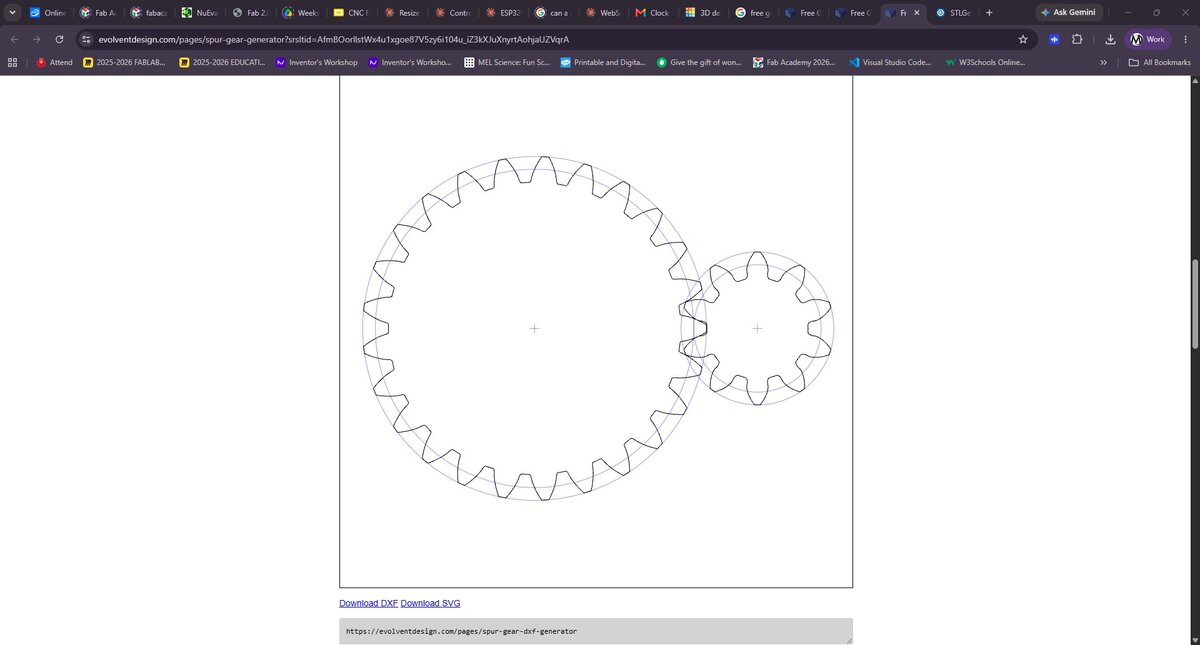
Next I found a free Gear Calculator that allowed me to design each of the gears I saw in on the first website. After generating the gears, I downloaded the .DXF files and imported them into Rhino. This did not work out because the gears were not properly aligning and I very quickly realized that the system would not work.
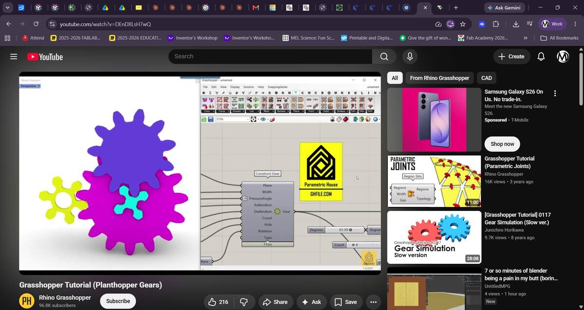
While in Rhino, it occured to me that I might be able to use Grasshopper to create parametric gears. Turning to a Youtube for guidance, I found a tutorial on how to use the Planthopper plugin. It does over adding gears, modifying its parameters and running a simulation. The final product can be baked as polysurfaces and modeled as regular 3D models.
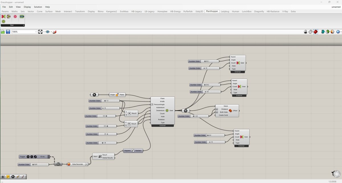
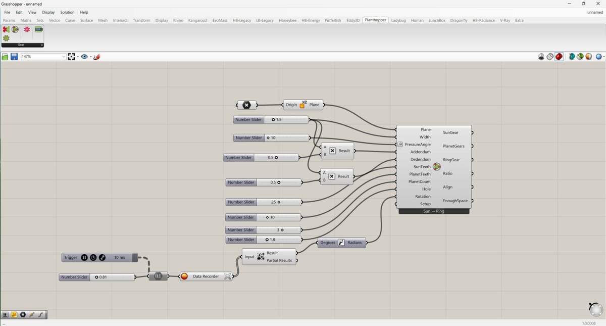
I followed the tutorial until I got a sufficient grasp on how the tools worked. I then designed my parent and child spur gears, and a planetary gear set.
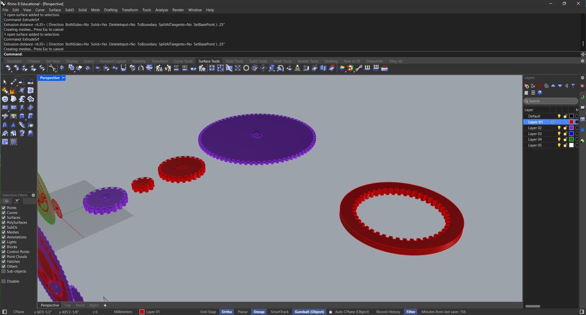
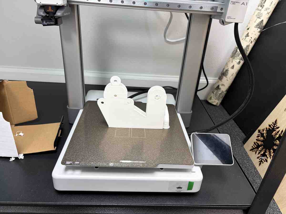
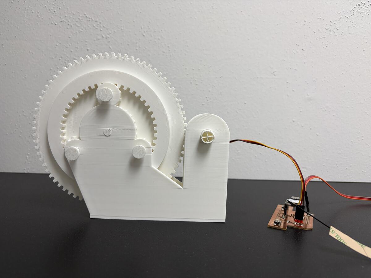
The 3D modeling went well. It took a while to account for the various design considerations which include pin and shaft placement and dimensions, gear thickness, and the enclosure. The gears are meant to be exposed because this is a tool for learning and further development.I designed it in a way would allow us to continue tinkering.
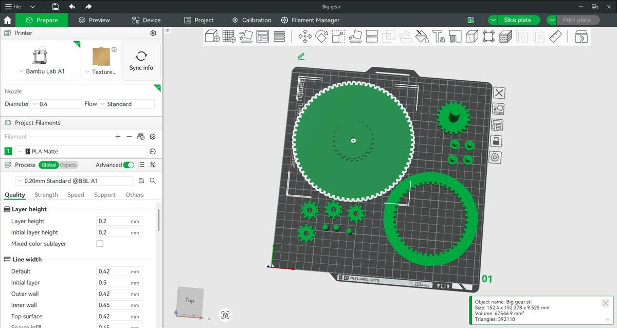
Emil and I reviewed the design changes. We decided to print it and test the physical prototype.
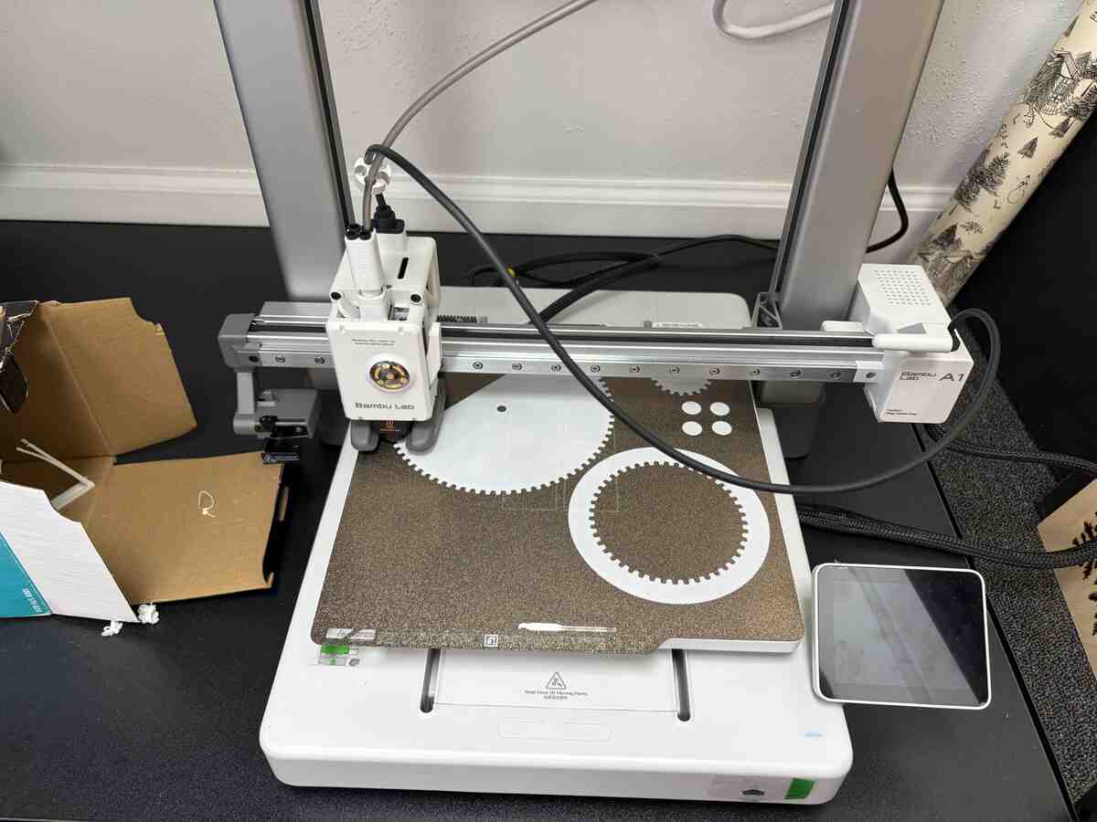
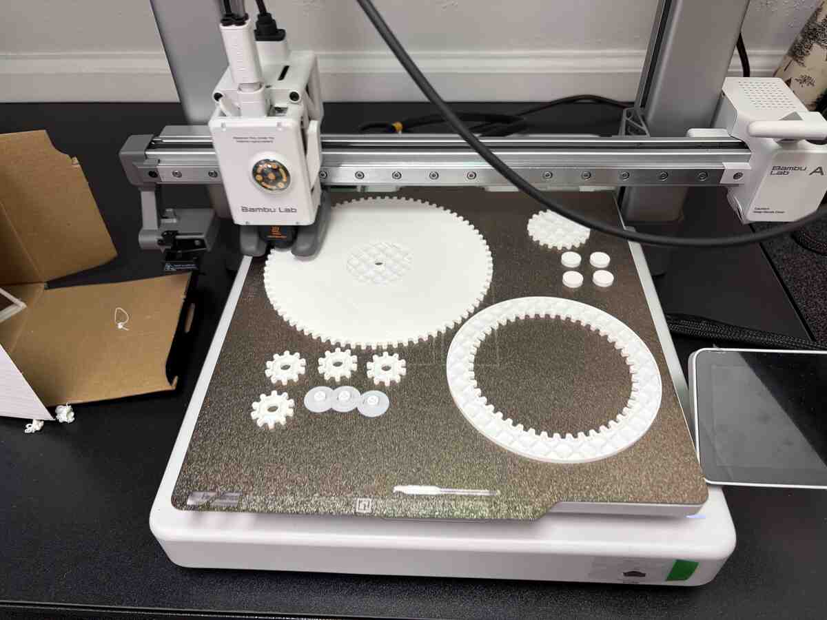
I printed the parts on a Bambu Lab A1 printer.
The assembly worked but I had to break the crankshaft to fit the components together. This made manually turning the gears rather difficult
Part 2: Machine Design
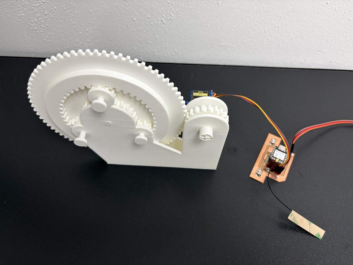
For my Input Devices assignment, I designed a PCB that used switches to control a servo motor. Using the PCB and code from that project, I was able to automate the gear assembly.
The connection was not fully resolved, but Emil and I were able to control the gear rotation much better.
Conclusion and Areas to Improve
The project was a great implementation of a PCB I already designed. It was a valuable opportunity to explore gear design and to use parametric tools to generate them. Going forward, I would like to refine the design and improve the system integration. I would also like to add more design elements for the project to function as a working time device.