

7. Computer-Controlled Machining
This week I learned to use the CNC at Moonlighter FabLab. My instructor Augusto went through the training with Alie and me. I also designed, milled and assembled a big fish installation for the ‘Make It Big’.
Week 7 Group AssignmentGroup Work and Safety Training
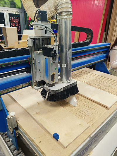
Augusto explained the various parts of the CNC.
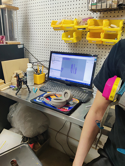
There is a dedicated PC for the CNC which uses Rhino software and Rhino CAM to layout and send the files for milling.
We got to help him with carefully placing ¾” plywood which we secured to the bed with screws.
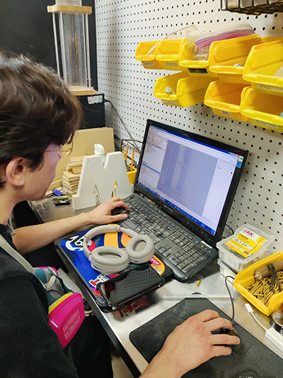
He demonstrated the processes of selecting the 2D profiles and preparing the plot settings.
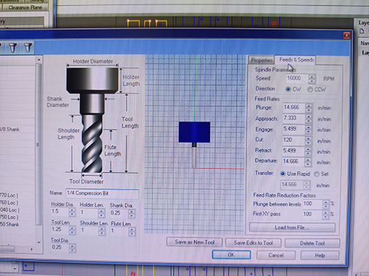
The tool settings we used for a profile cut were as follows:
- ¼ Compression Bit
- Holder Diameter: 1.5
- Holder Length: 1
- Shank Diameter: 0.25
- Tool Length: 1.25
- Shoulder Length: 1
- Flute Length: 1
- Tool Diameter: 0.25
The Feeds and Speeds settings were:
- Speed: 16000 RPM
- Direction: CW
- Plunge: 14.666 in/min
- Approach: 7.333 in/min
- Engage: 5.499 in/min
- Cut: 120 in/min
- Retract: 5.499 in/min
- Departure: 14.666 in/min
- Transfer: Use Rapid
- Plunge between Levels: 100%
- First XY pass: 100%
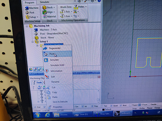
After preparing the tool path, we sent the plot.
What We Learned
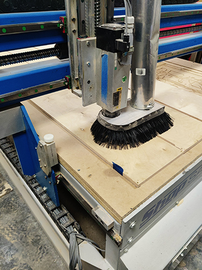
The ShopSabre 4896 is a CNC router with a 48" x 96" work area and 2.5-axis movement. It runs on Shop Sabre Router Controller software using a Windows-based controller. The spindle tops out at 18,000 RPM and is powered by a 9.38 HP motor. We are being tasked with training ourselves on safe operation of the CNC and characterizing its operations and capabilities.
Safety & Use:
- Don't reach for parts while the machine is on. Use the emergency stop if needed.
- Keep the vacuum on during all cuts.
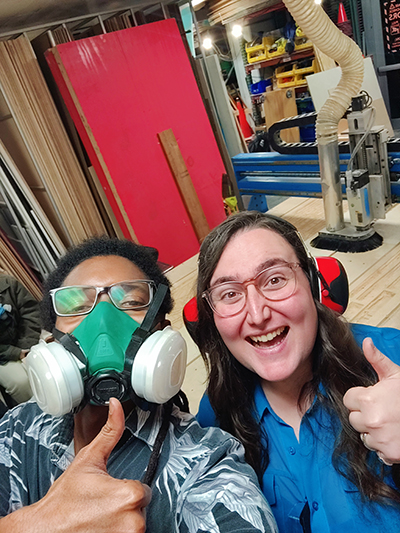
- Wear safety goggles inside the workshop.
- Kerf size depends on bit size and diameter.
- Inside corners will be round due to the bit shape and bit diameter.
- Use a 2D vector file for profile cuts.
- Use a 3D file type for 3D organic surfaces.
- Avoid designs with overhangs.
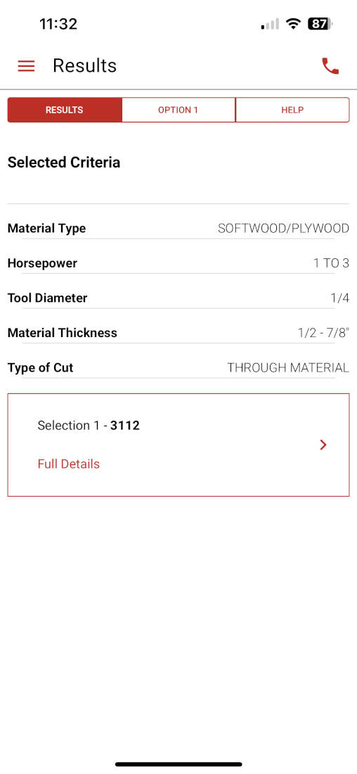
Material & Bit Pairings:
- Solid Wood – 2-Flute Endmill
- Plywood – Compression Bit
- MDF – 2-Flute Endmill
- Corrugated Plastics/Cardboard – Corrugated Bit
- Foam – Single-Flute Endmill
- Plastics – Single-Flute Endmill
- Thin Metal Composites – Single-Flute Endmill
Pick the right bit for the material you're cutting.
CNC Operations & Guidelines
2D Operations
- Profiling – Cuts along inner/outer edges of shapes
- Engraving – Adds shallow surface detail
- Pocketing – Clears material inside closed shapes
These operations are the most commonly used within our facility and space.
3D Operations
- Horizontal Roughing – Removes bulk in horizontal layers
- Horizontal Finishing – Refines detail using horizontal toolpaths
- Radial Machining – Radiates toolpaths from a center point, good for circular shapes
- Vertical Roughing – Clears material in vertical passes
- Vertical Finishing – Final vertical pass for fine detail
Design Tips
- Max cut area: 48" x 96"
- Leave a margin to screw stock to the table
- Keep at least 1" between parts to reduce vibration
- No vacuum hold-down—secure your stock manually
- Avoid cutting material over 2" thick or carving deeper than 3.5"
- Split complex designs into multiple parts
CNC Workflow
1. Load your material.
2. Turn on your machine.
3. Turn on the shop vacuum (ours is a ShopFox.)
4. Home the CNC
5. Load the correct bit for the job.
6. Tool height your bit.
7. Zero the Z-axis to your material.
8. Open or import your design file.
9. Program toolpaths using 2D or 3D operations.
10. Export toolpaths as a .NC file.
11. Open file in the Shop Sabre Router Controller.
12. Start cuts.
13. Stay by the machine and monitor until job completion.
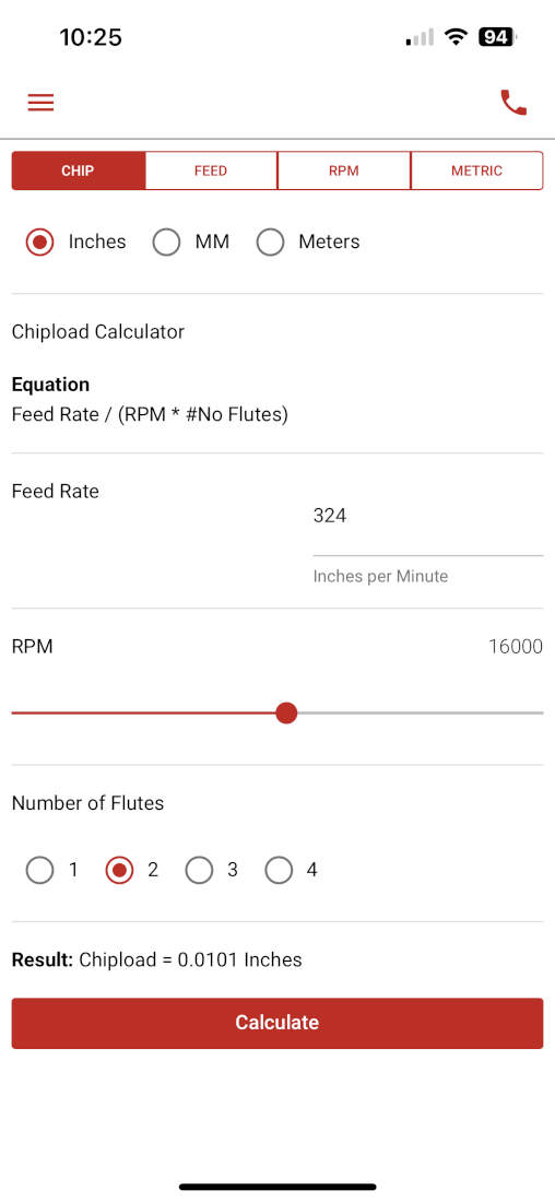
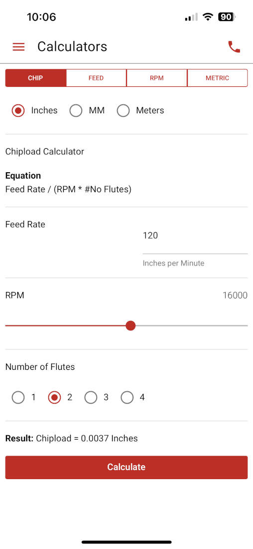
Feeds and Speeds - Our CNC tops out at 18000 RPM but we max it out at 16000 RPM for longevity purposes. The feeds and speeds we use for a 1/4 inch flat endmill are located on Slide 11. Based on the Vortex Tool app, we can push our feedrate to 324 ins/min if we wanted to. Additionally our chipload at the default 120 in/min we leave it at would be 0.00375 and if set to the 324 in/min mentioned earlier it would be 0.010125.
feed rate (inches per minute) / (RPM x number of flutes)
120 (inches per minute) / (16000[RPM] x 2[number of flutes]) = 0.00375
324 (inches per minute) / (16000[RPM] x 2[number of flutes]) = 0.010125
Cut Depth - This is associated to diameter of the bit, but for our typical purposes and for this test we use a 1/4" bit and it can typically cut all the way through a 3/4" sheet of plywood without increasing the amount of passes. If it were a 1/8" bit, we would make sure that the passes were at least two.
Stepover - (diameter/2) This parameter is determined again by the diameter when divided by two. If pocketing or surfacing this is essentially the distance between each successive pass. The larger the bit the less runtime but less smooth a cut is, the smaller the bit the more runtime but smoother the cut is.
Bit Deflection - This is determined by cutting parameters relating to feeds and speeds and cut depth. In the case of our CNC, we do not cut anywhere near the recommended feedrate of 324 in/min. Since we cut it at 120 in/min. we stay at a safe distance away from any bit deflection issues but are still within a good range that cuts our materials quickly and properly. If we were to cut above 324 in/min. we would risk bending or flexing our bit which leads to inaccurate cuts/ surface imperfections, and if our bit does not break under the pressures being placed upon it we risk it going off center creating runout issues.
Runout - Runout is a measure of how off center a bit is. To determine if our bit was off center we used a right angle tool and flattened it on top of our work surface and lined up the other end against the endmill. Please keep in mind that we had to flip the endmill around temporarily to see how straight this alignment really was, otherwise the flutes would not have given us a proper idea of how centered it was.
Designing My Test File
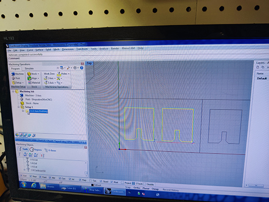
I designed samples for a push fit installation project I planned for Maker Faire Miami. After making the 2D profiles, I selected them and began setting up my file.
Toolpath Accuracy - Regarding toolpath accuracy, kerf plays a large part in it but so does the programmed toolpath itself. When conducting those tests we used the "Profiling" command which has the option of being set to the center of the line, or inside or outside the line. We choose to cut outside the line and the CNC automatically offsets the toolpath by half the kerf. Additionally, we used a right-angle tool to determine how straight our cuts were and if there was any deviation in its angles. There were none.
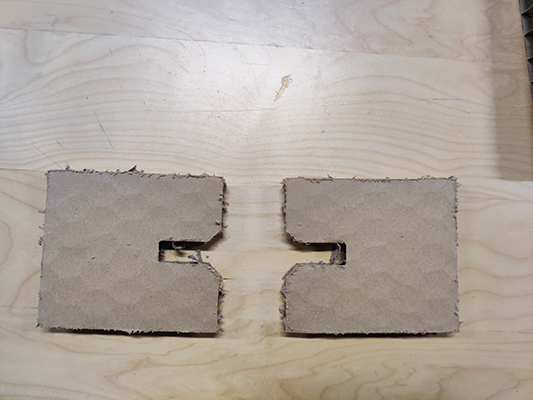
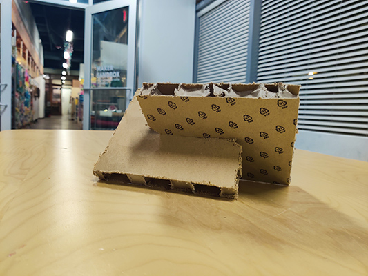
We were also testing a new tool that could be used on ¾” honeycomb cardboard. The cut went well, unfortunately the finish was very messy with frayed edges and excessive dust. We decided to switch to a combination of laser cutting and finishing by hand.
Designing and Make It Small
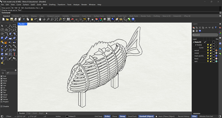
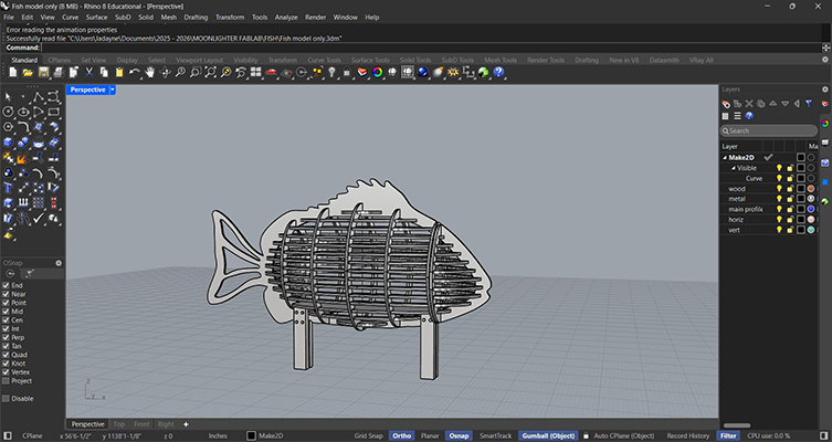
For the assignment, I worked on a design I did for an outdoor installation. It was designed in Rhino8 as a push fit assembly.
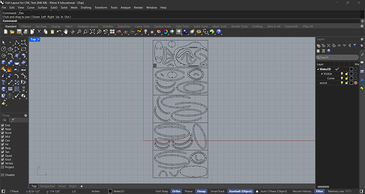
I then used the Make2D command to make the profiles and arrange them on 4’x8’ sheets. The challenge was to get the pieces on as few sheets as possible while maintaining a minimum 1” spacing between the elements.
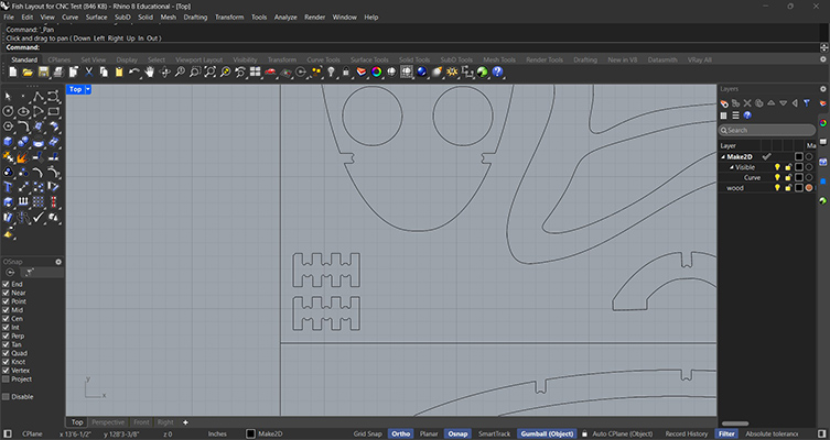
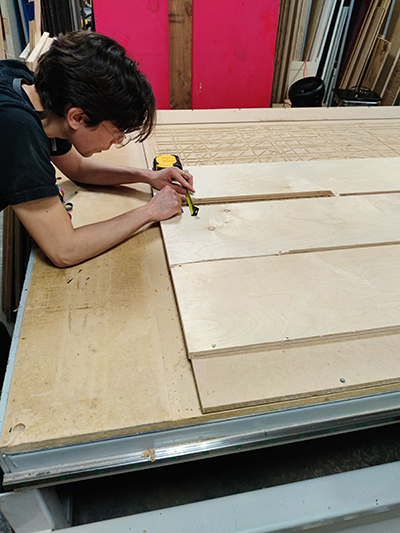
To ensure the best fit, I added dogbones to all of my notches. I also did a sample to test the kerf for the material we would be using.

Before sending the cut, I had to plan the leg assembly and connections.
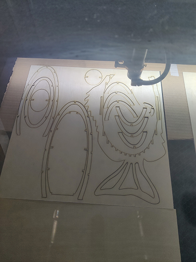
I also made a scaled model of the design to work out how the profiles would fit together before making an expensive mistake.
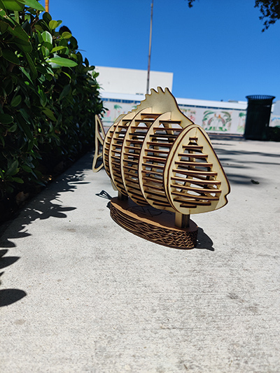
The wooden model worked well and I got to experiment with a hinge.
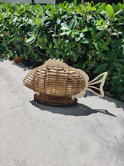
Make It Big
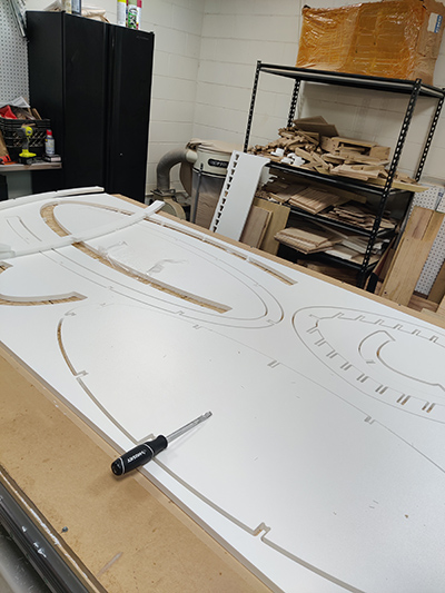
I loaded the CNC with the HDPE and ran the kerf test first. After confirming that our settings would work for the material thickness, I sent the design profiles to cut.
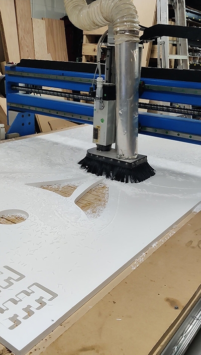
The process was very messy so I monitored the milling and vacuumed the flakes to avoid complications.
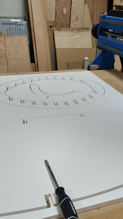
I carefully removed the cutout profiles with a screwdriver. The edges were extremely sharp and the HDPE was smooth and slippery making it dangerous to hold.
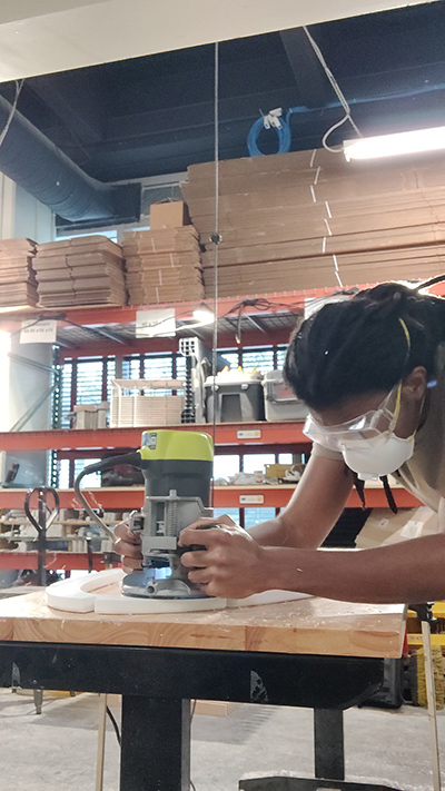
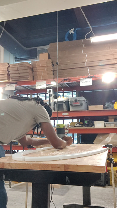
To make the parts safe to hold, I cut fillets along the edges using a hand held router.
Augusto began the assembly while I continued filleting the edges.
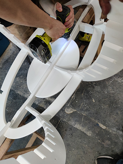
We worked together to screw the parts screwed in place.
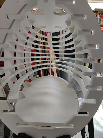
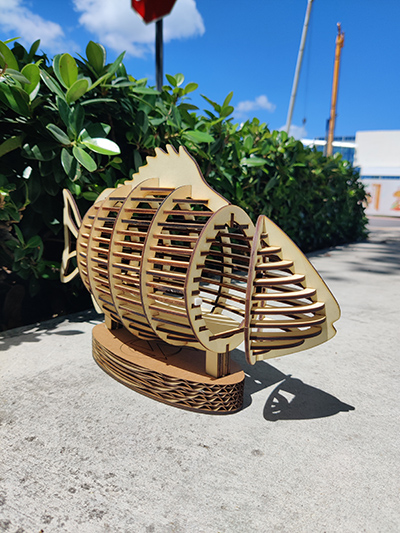
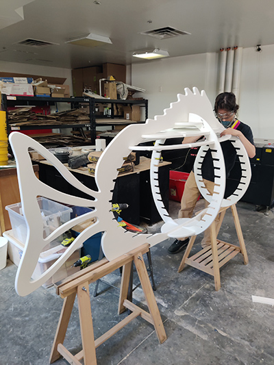
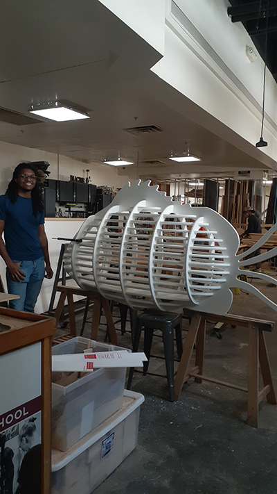
The ribs were very precisely cut based on the Rhino model but this made them difficult to fit together in the assembly. We also had the challenge of not knowing exactly which rib went in which slot.
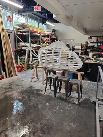
We eventually got them all fitted together and clamped the head and body in place.
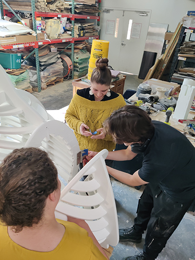
My instructors, Augusto and Vicky, along with the directors of Moonlighter FabLab joined in to figure out the hinge placement and how to mount the head on the body.
I was happy the team could join in to bring my design to life.