

Group Assignment — Week 6: Electronics Design
Group Project
Testing the PCB data signals with a Logic Analyzer has revealed a clear rise and fall when the switch is pressed and the LED blinks.
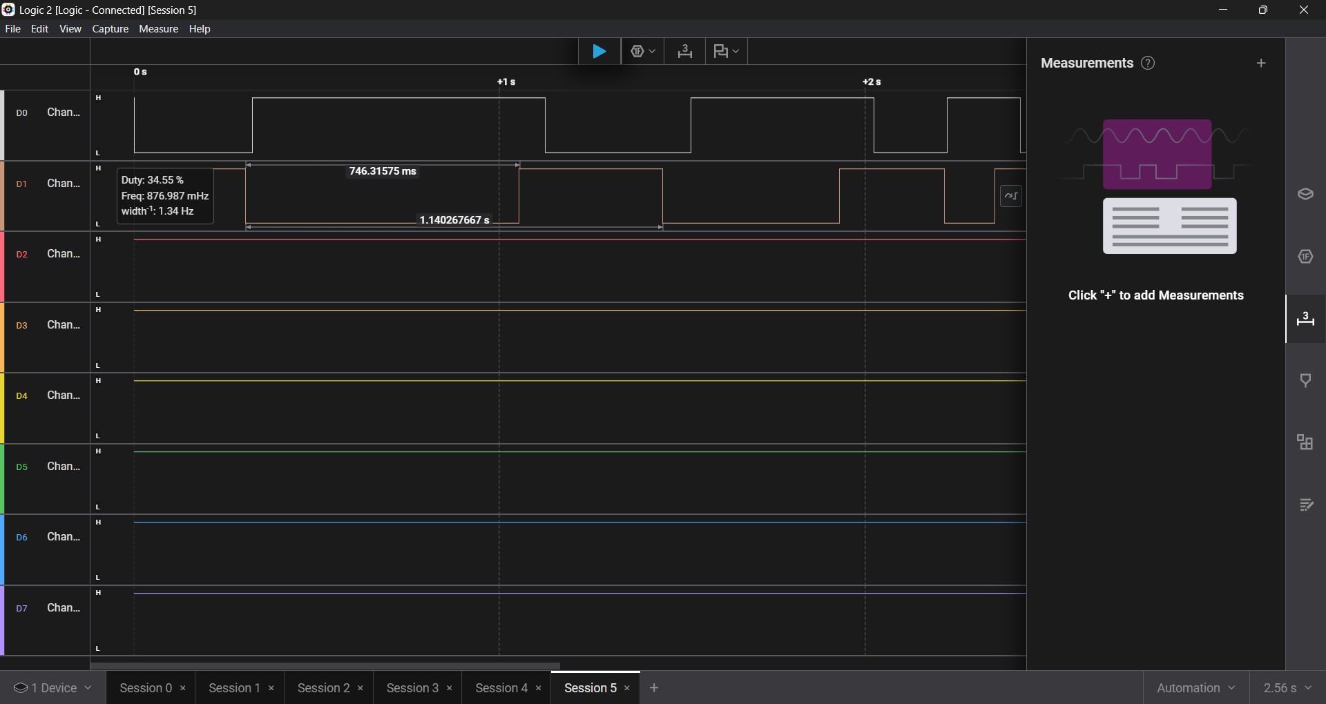
The switch was connected to Channel 1 and the LED was connected to Channel 2. You can see that Channel 1's baseline is consistently low when idle, while Channel 2's is high. These values are inverted when the switch is pressed. This happens almost simultaneously and with similar wave lengths. My conclusion is that each component has a value on a binary; a 1 and a 0. When an input is detected, the value flips which causes the value of the connected component to also flip.
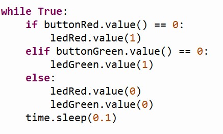
While writing this conclusion, I remembered that the MicroPython script actually mentions this logic. The Logic Analyzer has confirmed the logic in the code.