Overview
This week helped me understand what 3D printing can do. I wanted to see real limits, not only read general rules.
So I tested two printers with the same overhang model. I also used Polycam to scan a small object.
This helped me compare visual scans with fabrication-ready meshes. It also helped me think more about slicing choices.
Group Assignment — Testing Printer Design Rules
For the group work, I compared the Bambu Lab A1 Mini and P1C. The goal was not to find a winner.
I wanted to see how each machine handled difficult geometry. Both tests used PLA and the same benchmark model.
I focused on the curved overhang area. It showed where unsupported printing started to fail.
Printers Used
- Bambu Lab A1 Mini — bedslinger structure, open frame, easy setup
- Bambu Lab P1C — CoreXY structure, enclosed machine, more rigid motion
Test Setup
- Material: PLA
- Nozzle: 0.4 mm
- Layer height: 0.20 mm
- Supports: disabled
- Purpose: find the practical overhang limit
Benchmark Model
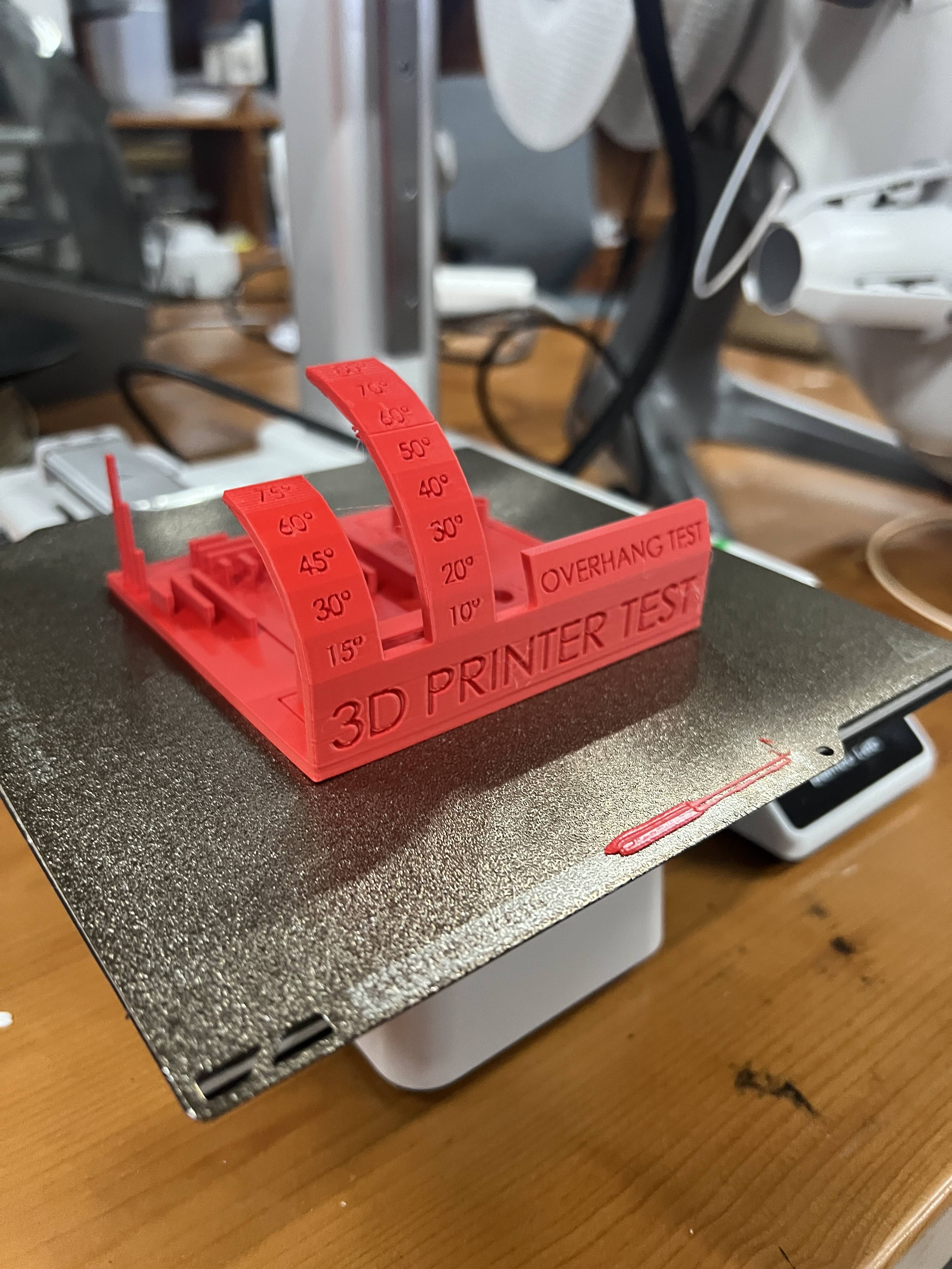
A1 Mini Result (Red Print)
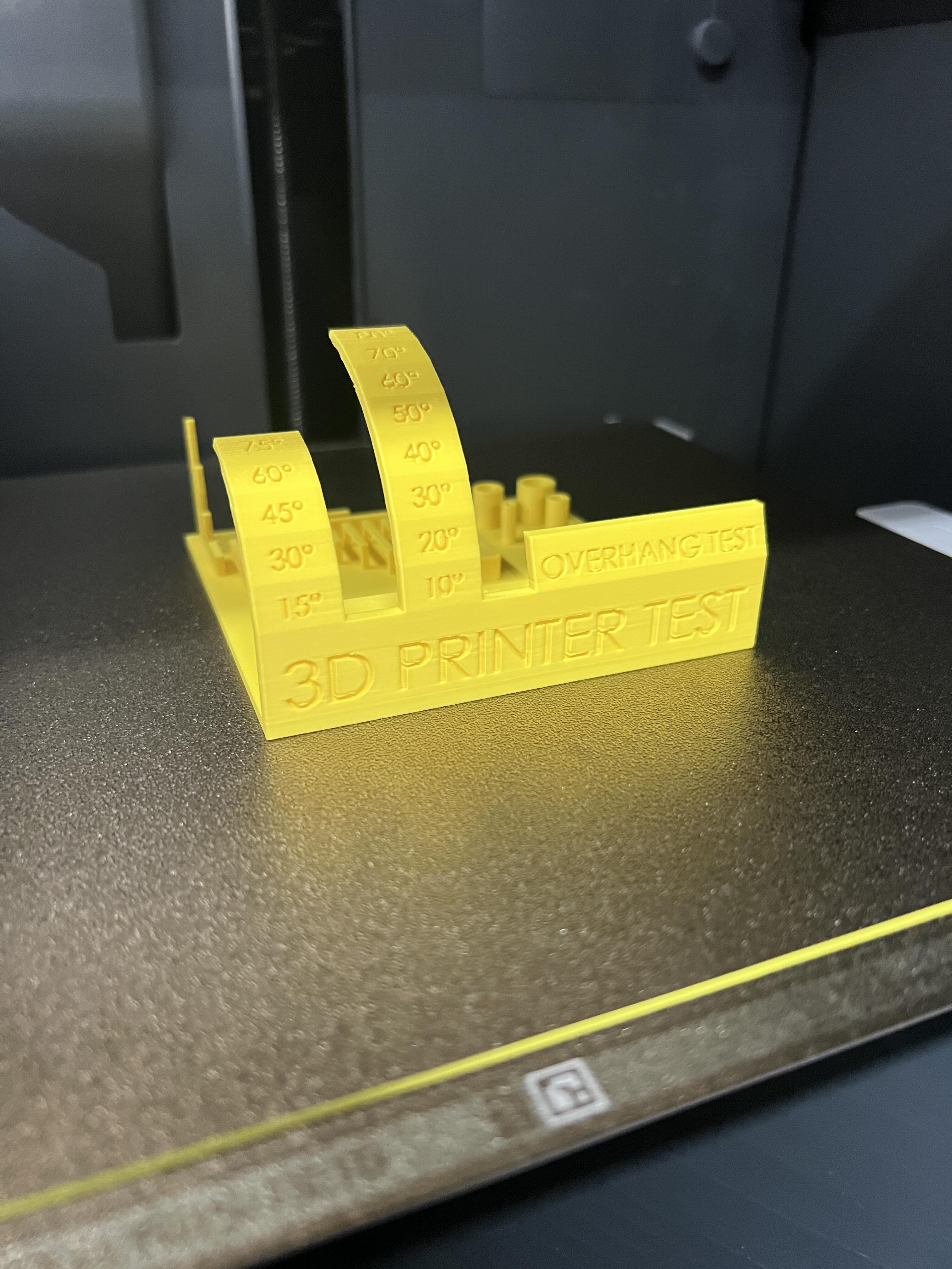
P1C Result (Yellow Print)
Close-up Observation
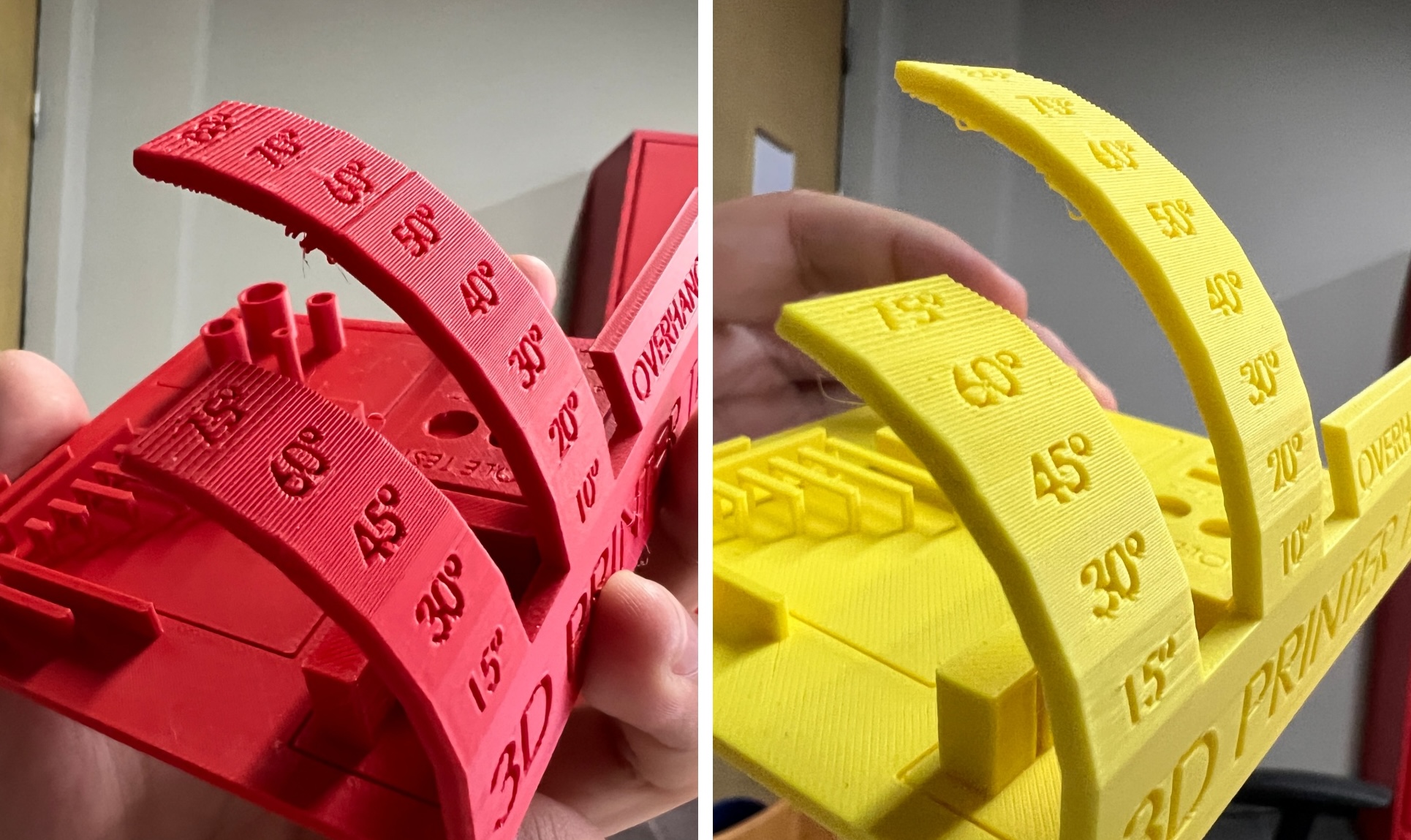
Critical Observation
Both printers started to struggle near 50 degrees. That gave me a real reference for future designs.
For safer prints, I should keep unsupported angles around 45 degrees or lower.
Printing Summary
| Test | A1 Mini | P1C |
|---|---|---|
| Overhang limit | ≈ 50° | ≈ 50° |
| Surface quality | Good | Slightly smoother |
| General stability | Reliable | Reliable |
Both machines worked well with these PLA settings. The P1C looked a little smoother. The A1 Mini was still good enough for this test.
Individual Assignment — Additive-Only Object
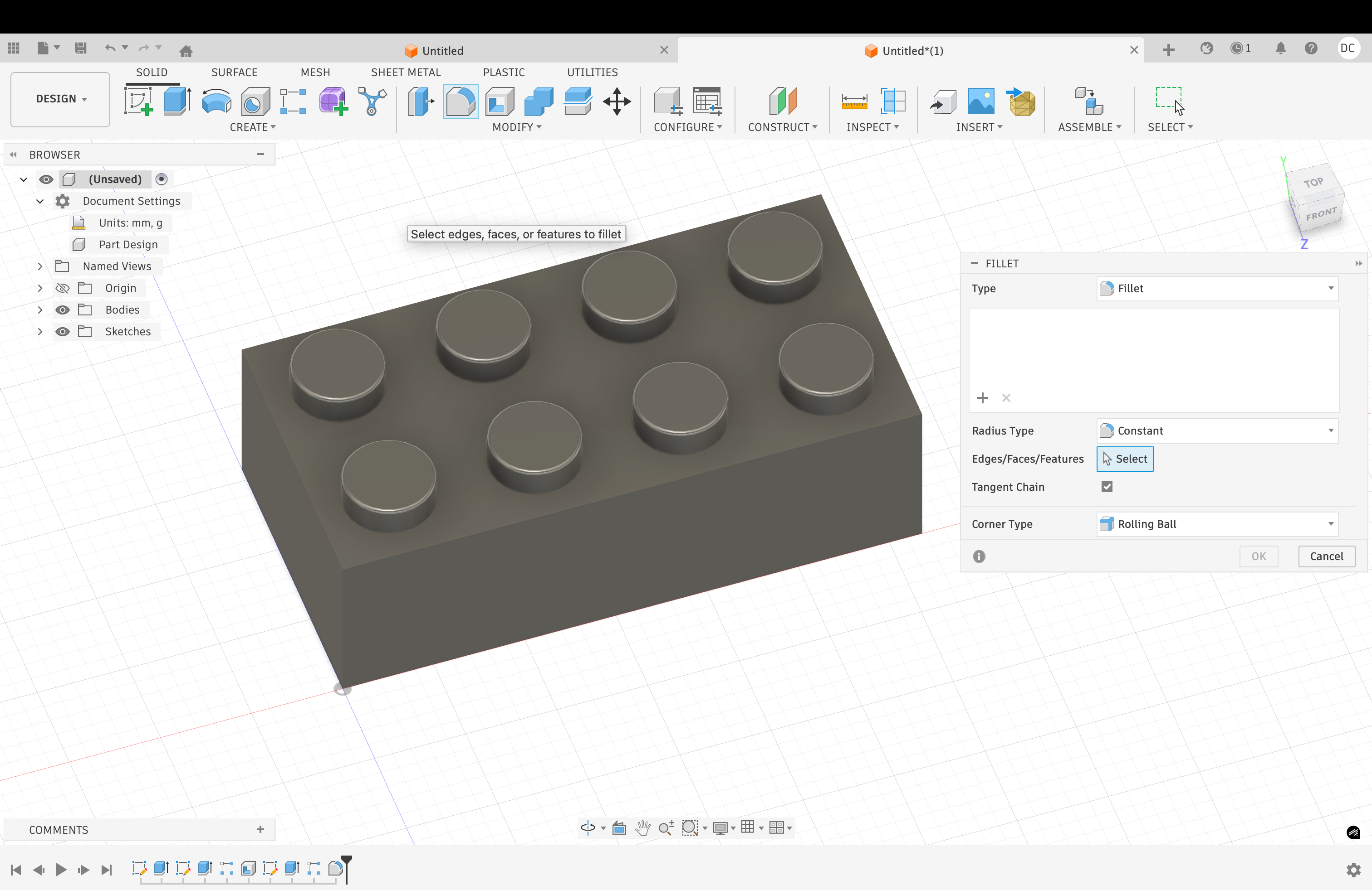
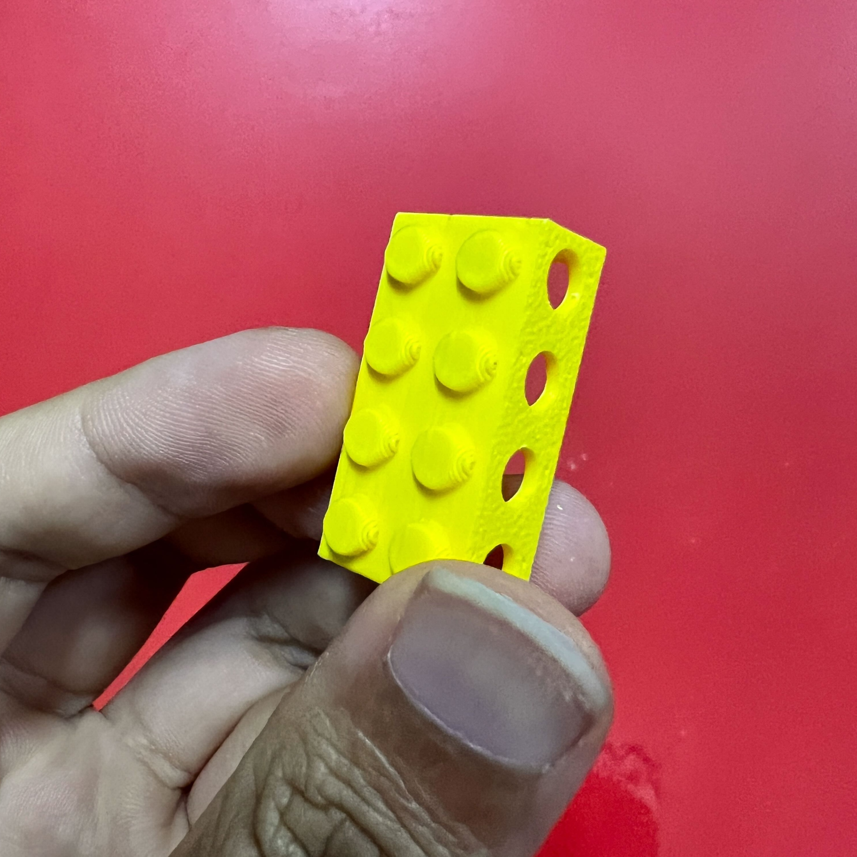
I designed a hollow LEGO-inspired block. The outside looks simple, like a normal toy brick.
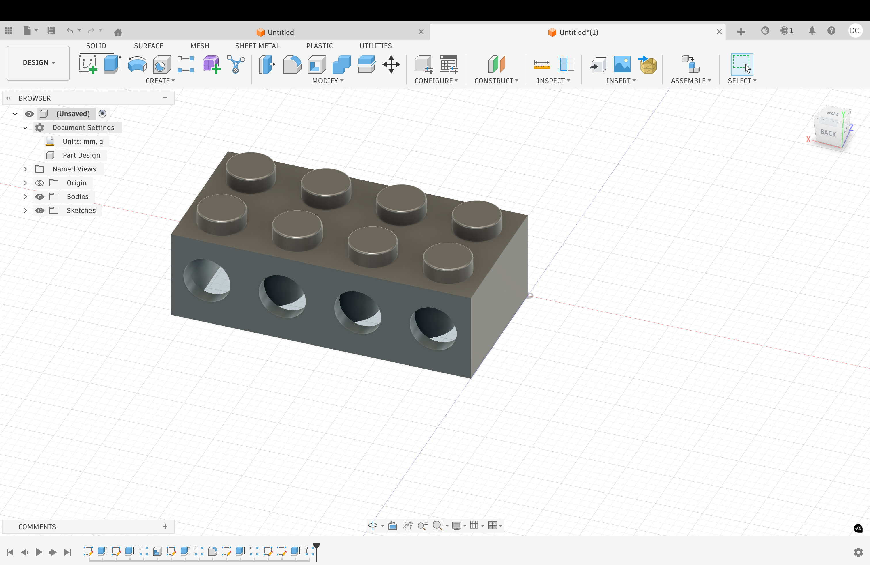
The inside has hollow spaces and tube-like shapes. These inner areas show why additive manufacturing is useful.
This object is hard to make with CNC machining. The cutter cannot reach the enclosed inner areas.
3D printing works better here. It builds the form layer by layer.
Step 1 — Base Model
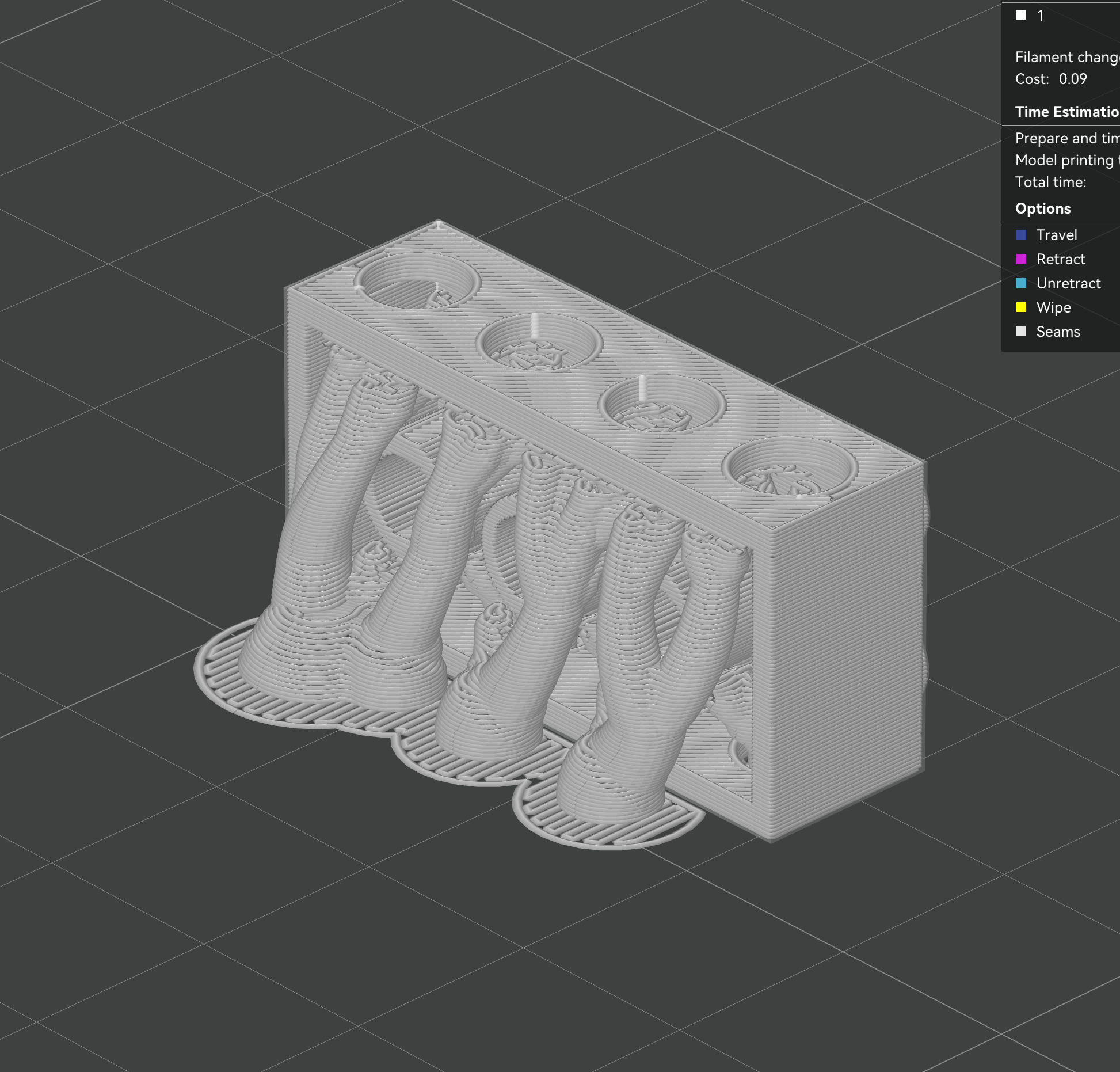
Step 2 — Hollow Structure
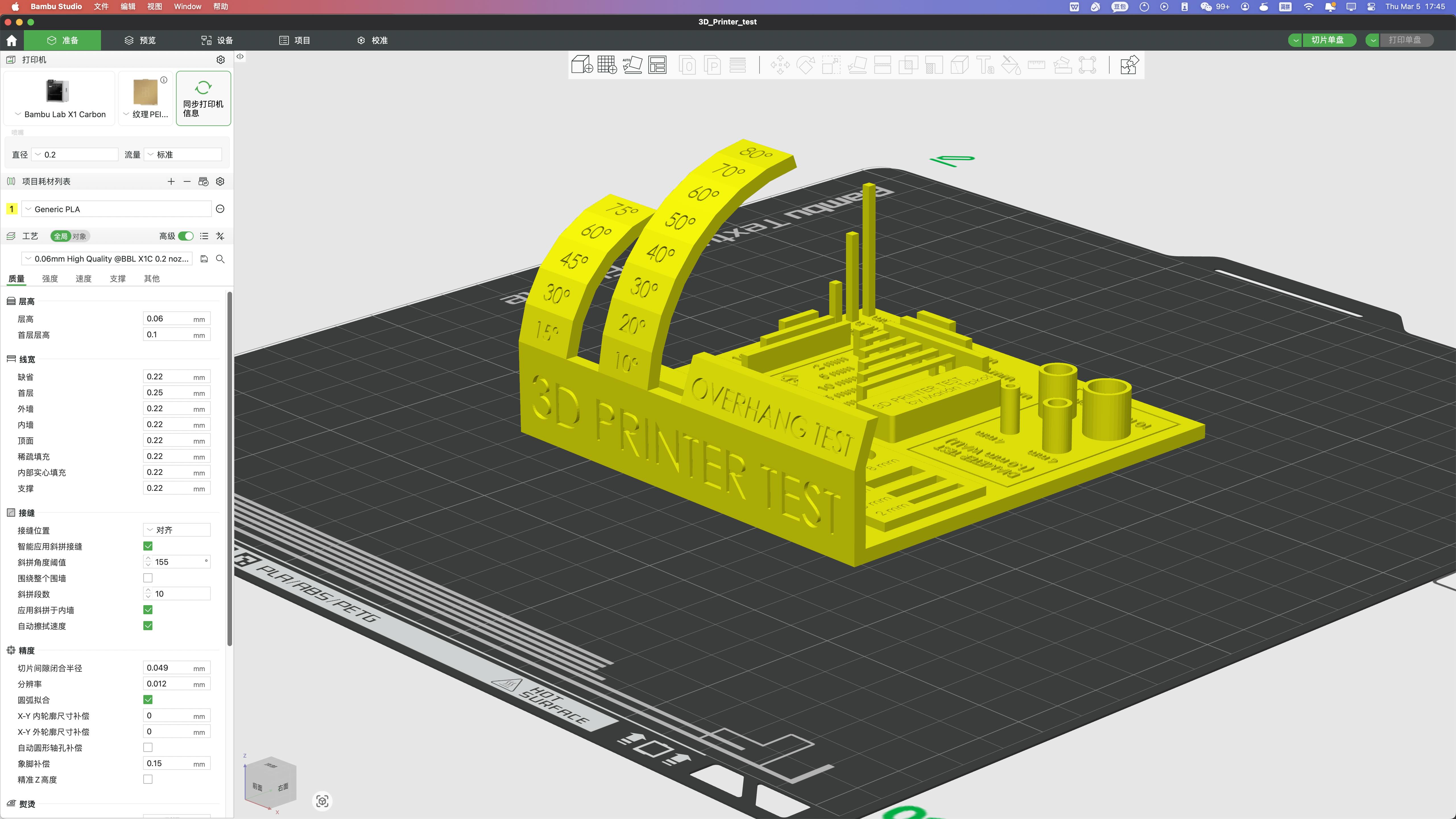
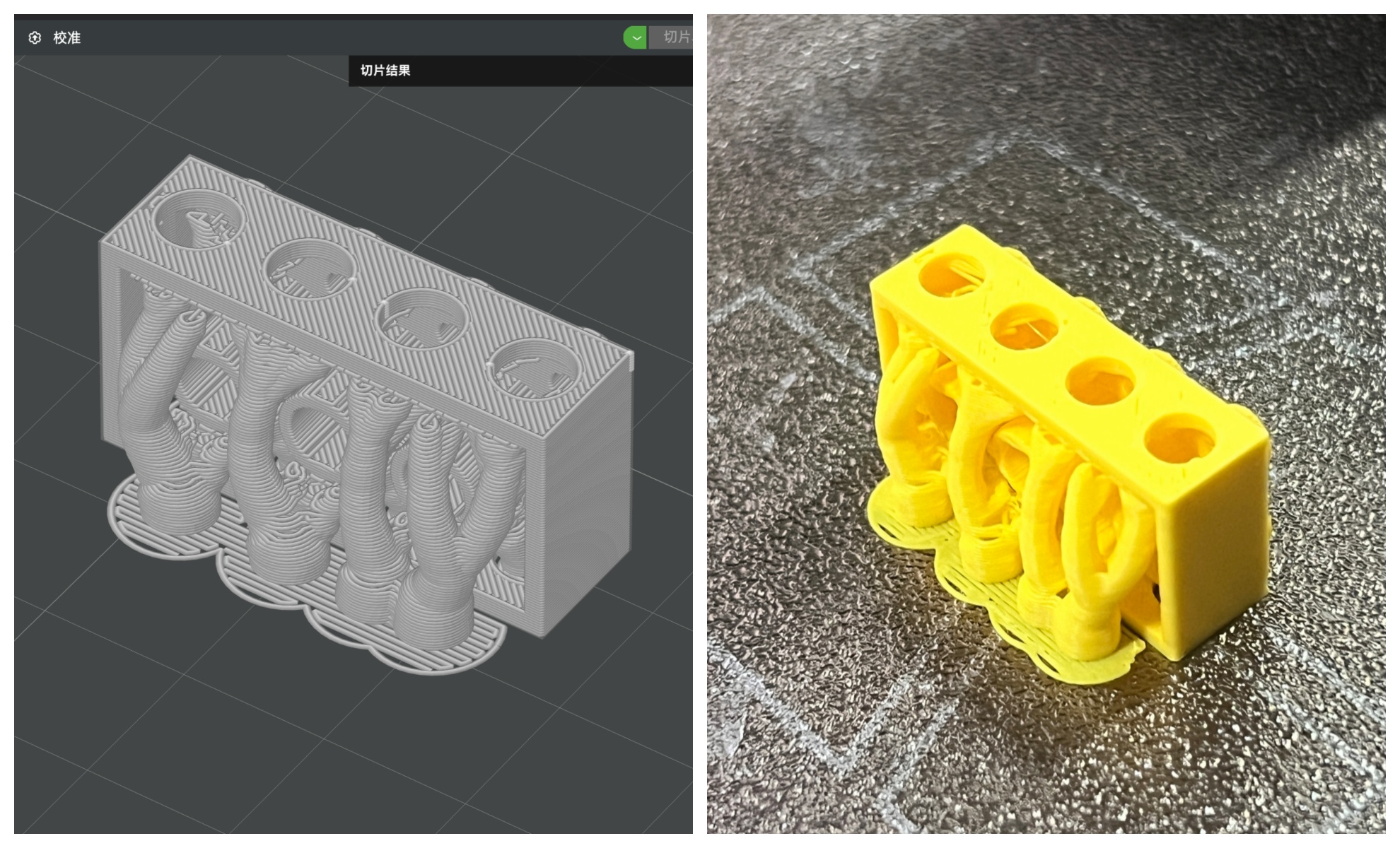
Step 3 — Slicing
Slicer Settings and Printing Direction
This part answers the slicer feedback. I explain the settings, direction, and support choice for my LEGO block.
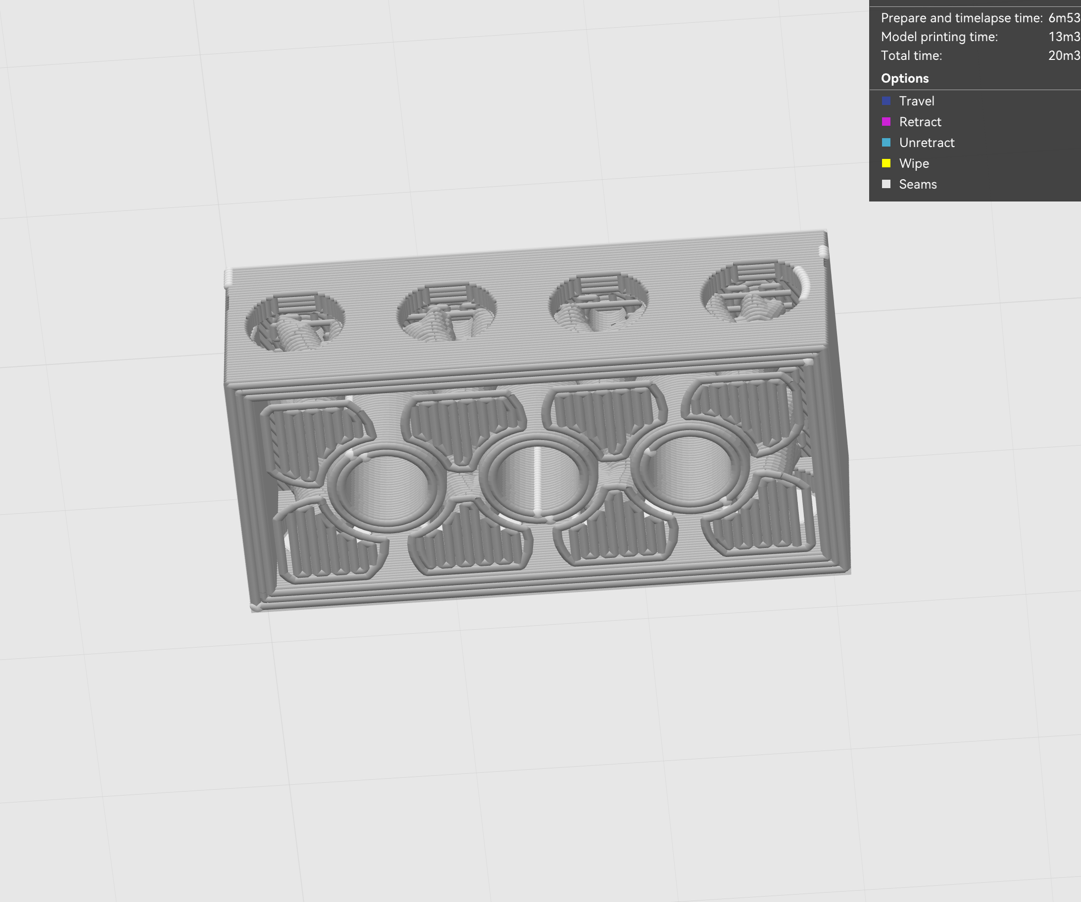
Why I Printed It on Its Side
I printed the block on its side. This made more toolpaths follow the long body.
That can make the brick feel stronger. It also used less internal support.
Less trapped support means easier cleaning. This mattered because the brick has many inner spaces.
The brick also has many holes. Hot PLA can sag if a hole is poorly oriented.
PLA also shrinks a little while cooling. So orientation can affect hole accuracy.
Why I Rejected the Other Direction
I tested another direction in the slicer. It placed many supports inside the hollow brick.
Those supports would be hard to remove. They could also leave more marks inside.
Slicer Decision Table
| Slicer decision | My choice | Reason |
|---|---|---|
| Model orientation | Printed on its side | More toolpaths followed the long body. |
| Rejected direction | Upright direction | It trapped too much support inside. |
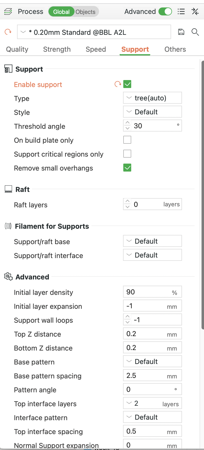
| Support type | Tree support | It used less support in the hollow area. |
| Threshold angle | 30 degrees | It caught steep overhangs earlier. |
| Layer height | 0.20 mm | It balanced time and surface quality. |
| Nozzle and material | 0.4 mm nozzle and PLA | They matched the group test. |
Why Support Was Needed
Support was needed because this was not a solid block. It had hollow spaces, side openings, and floating tube shapes.
Some layers would start in air without support. These areas could fail during printing.
In our group test, curved overhangs became risky near 50 degrees. So I did not rely only on bridging.
I used tree support to make the print safer. It also reduced material compared with heavier support.
Support Problems and Next Improvement
The support helped the print succeed. But it left marks on the inner surfaces.
Some support was still hard to remove. Next time, I would make larger side openings.
I would also use softer tube angles. This could reduce support and make cleaning easier.
Step 4 — Printed Result
What I Learned from the Object
This object made one lesson clear. Hidden geometry is easy to model, but hard to clean.
- Orientation changes strength, support amount, and accuracy.
- Support planning matters more in hollow objects.
- Tree support saves material, but still leaves marks.
- Additive-only design is really about tool access.
3D Scanning Workflows
For scanning, I used Polycam on my phone. I scanned a real object and made a digital mesh.
I chose this workflow because it was simple. It only needed a phone, a stable object, and enough photos.
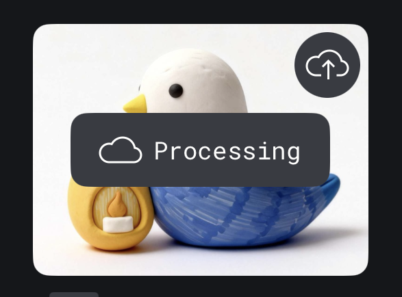
I scanned a small bird-shaped object. My goal was to learn the workflow, not make a perfect part.
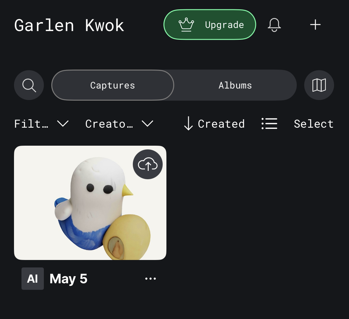
Step 1 — Object Capture

Step 2 — Cloud Processing
Step 3 — Processed Scan
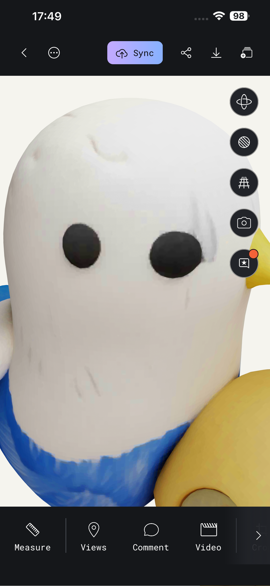
Step 4 — Detail Check
Final Preview Video
What I Learned from Polycam
Polycam is useful for fast visual scans. It captured the main shape and color well.
But the mesh was not very accurate. Small details were softened, copied, or distorted.
So I should not treat the scan as a final print file. It still needs checking, cleanup, and possible remodeling.
Reflection
This week made 3D printing rules feel real. I could see overhang limits directly on the printed test.
The test gave me one useful rule. Unsupported curved parts became risky near 50 degrees.
The LEGO block showed another lesson. Designing hidden spaces is easy. Cleaning hidden spaces is not easy.
The Polycam scan was useful for visual reference. But the mesh was not ready for precise fabrication.
AI Use Statement
I used AI to help me write and organize the HTML structure of this page. AI also helped me improve the English writing and make the sentences clearer.
The design idea, 3D model, printing direction, slicer decisions, photos, test results, and final documentation choices were completed by myself.
I reviewed and edited the AI-assisted HTML and text before adding them to my Fab Academy website.