Computer-controlled machining
Week 07 · Computer-Controlled Machining.
weekly schedule.
| Time block | Wed | Thu | Fri | Sat | Sun | Mon | Tue | Wed |
|---|---|---|---|---|---|---|---|---|
| Global class | 3 h | |||||||
| Local class | 1,5 h | |||||||
| Research | 1 h | |||||||
| Design | 2 h | 2,5 h | ||||||
| Fabrication | 1 h | 1 h | 3 h | 1,5 h | ||||
| Documentation | 2 h | 2 h | 3 h | 1 h | 1 h | |||
| Review |
overview.
This week is about large-format CNC machining — designing parts for real-scale fabrication, generating toolpaths, setting up the machine, and physically building something that a person can actually use. It’s the most physically demanding week so far, and the one where things are most likely to go wrong in interesting ways.
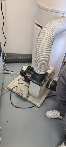
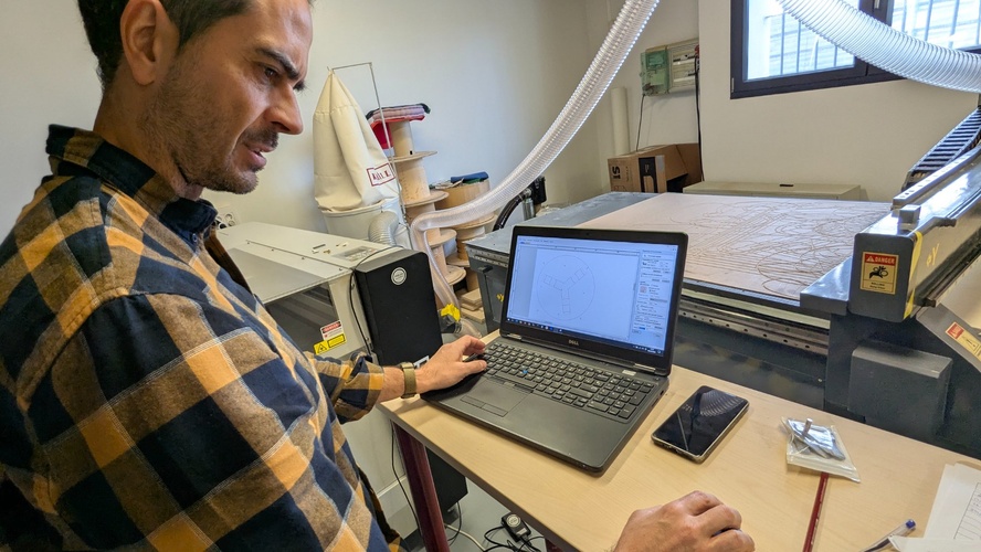
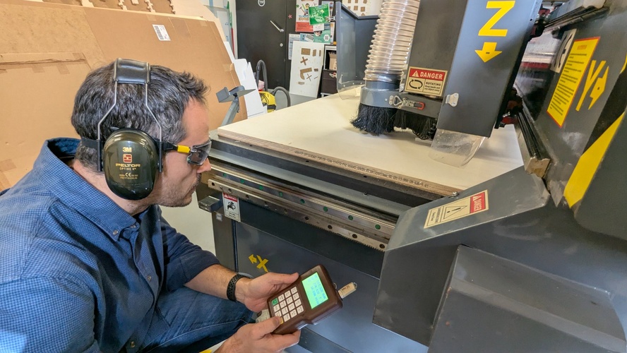
The machine at Fab Lab León is a TEC-CAM 500 (Pérez Camps), a large-format CNC router with a vacuum table and a RichAuto A11 controller. My instructor Pablo has been working with this machine for years, so I was in good hands — even when things didn’t go as planned.
group assignment.
The group assignment for this week covers: operating the machine safely, documenting the test for feeds and speeds, and characterising the joint behaviour for the material we’re using.
→ Fab Lab León 2026 Group Page.
The machine: TEC-CAM 500.
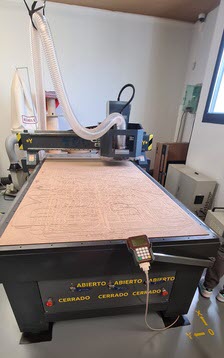
The TEC-CAM 500 is a large-format CNC router manufactured by Pérez Camps. Its nominal footprint is 1800 × 3000 mm, with a working area of 1220 × 2440 mm (the difference accounts for the machine structure and mechanical limits). Key specs from the lab documentation:
| Parameter | Value |
|---|---|
| Nominal dimensions | 1800 × 3000 mm |
| Working area | 1220 × 2440 mm |
| Spindle | 2.2 kW, water-cooled |
| Gantry height | 120 mm |
| Repeatability | 0.025 mm |
| Fixturing | Vacuum pump, 3 independent channels |
| Weight | 900 kg |
| Max material thickness | ~40 mm (tool-dependent) |
| Accepted file formats | STL, DXF, and others |
| Compatible materials | Plywood, MDF, bakelite, PP, solid wood, PVC, brass, foam, acrylic |
Safety.
Before touching anything in the CNC room, everyone signs a safety document provided by the lab. The TEC-CAM 500 is the most dangerous machine in the lab — the spindle runs at up to 18,000 RPM, the gantry moves fast, and a mistake can be irreversible. The rules are not suggestions.
The rules split into two categories:
Personal safety:
- One person operates the machine at a time.
- Never disconnect cables by pulling, or with wet hands.
- Hair tied back; no loose items — necklaces, scarves, bracelets — that could catch a spinning tool.
- Maintain safe distance from the gantry during movement and cutting.
- PPE inside the CNC room: ear protection and safety glasses at all times; dust mask when needed.
Machine rules:
- Any malfunction or emergency: press the emergency stop or disconnect the machine; notify the Fab Lab Manager (emergency contact details are posted in the CNC room).
- Do not use if there is burning smell, abnormal noise, or smoke.
- Cleaning and unclogging only with the machine disconnected.
- Repair and maintenance under Fab Lab Manager supervision only.
- No metals or liquids in contact with internal components.
- Never use compressed air to clean the electrical panel.
- Never power on with the pendrive already connected to the controller.
- Always verify material thickness before machining.
- Format the pendrive before use; save each job with a new filename — never overwrite.
- Always activate the vacuum fixturing system; check for obstructions before use.
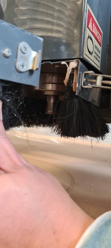
- With materials that produce fine chips, activate the dust extraction system.
- Clean the machine and workspace after every session.
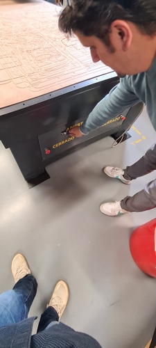
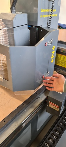
The vacuum table.
The table uses a vacuum pump to hold the material down — no clamps needed. It has three independent suction channels, each controlled by its own ABIERTO/CERRADO switch on the front of the machine. For a full-size sheet, all three zones are open. For smaller boards, you can close unused zones to concentrate suction where the material actually sits — but you need to surround the board with scrap pieces to maintain the sealed area and prevent air leaks.
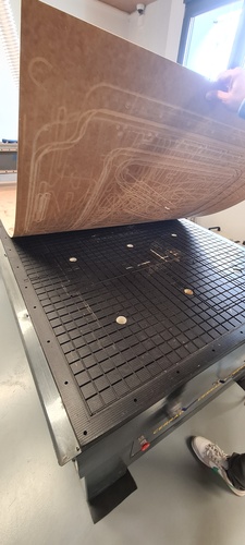
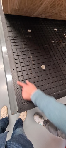
Underneath the working material sits the martyr board — a 3 mm thick sacrificial layer that absorbs the final pass of the cutter when it goes slightly past the material thickness. It wears down over time, which is why the surface looks like a map of every job that has ever run on the machine.
Material.
The board I used is poplar-core plywood with birch face veneers. The stamp on the edge reads:
EFFICIENCY POPLAR 1508 Y+V2V3 PR2 · 2500×1220×18mm · CE EN 13.986 EN 636-1 E1
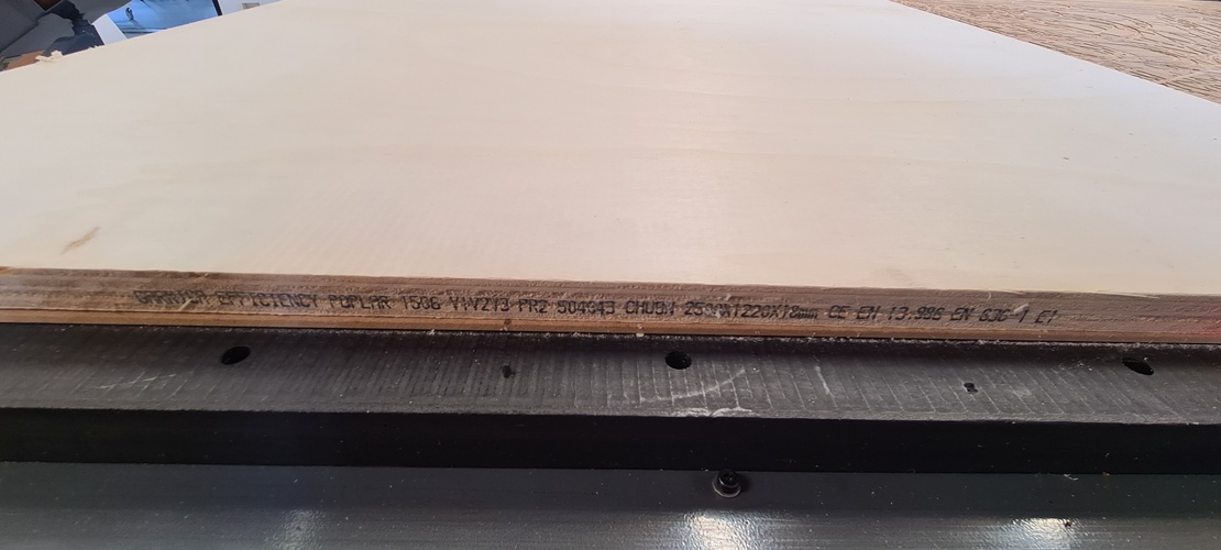
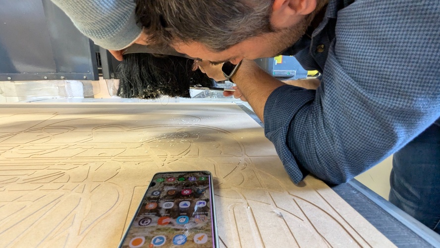
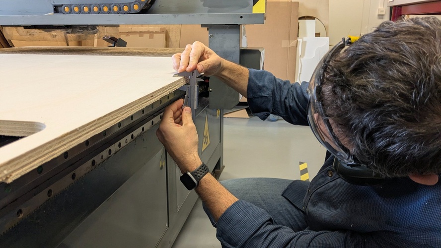
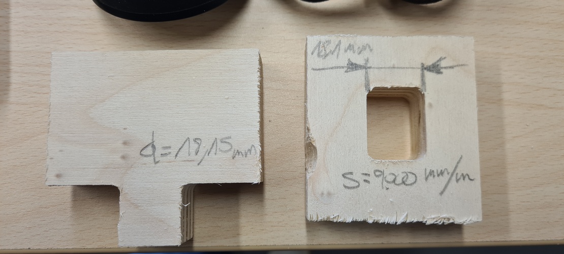
Nominal thickness is 18 mm, but I always measure the actual thickness twice with calipers before entering any value in Aspire. In CNC work, measuring twice before cutting once is not a cliché — it’s the difference between a clean job and a ruined board.
Measure twice, cut once.
The real thickness of this board was 18.15 mm. There is a label on the gantry that says — in capital letters — “ALWAYS CHECK THE MATERIAL THICKNESS”. It is there for a reason.
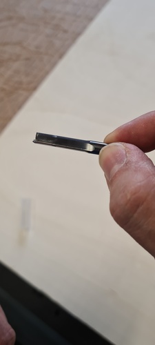
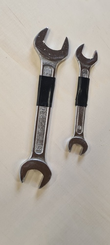
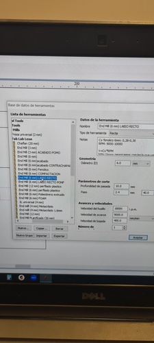
The end mill.
The standard mill at Fab Lab León for plywood cutting is a 6 mm single-flute straight end mill (labio recto in the tool library). Single-flute because it evacuates chips more efficiently than multi-flute tools on wood, which prevents heat build-up and recutting.
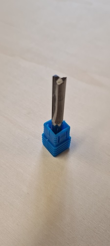
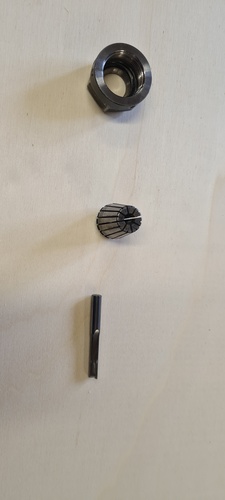
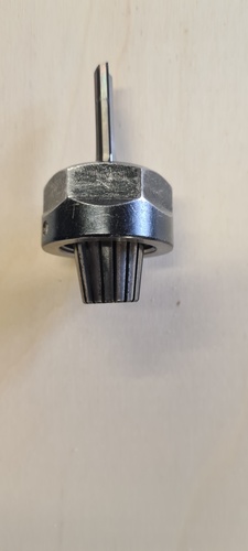
Installing the end mill (done before powering on the machine):
- Snap the collet into the collet nut — it clicks into place.
- Insert the end mill into the collet.
- Thread the nut onto the spindle: rotate backwards until you feel a click, then forward to tighten.
- Tighten with two flat spanners: 21 mm on the collet nut, 30 mm on the spindle flat — one-hand force only.
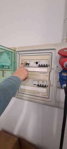
Electrical startup.
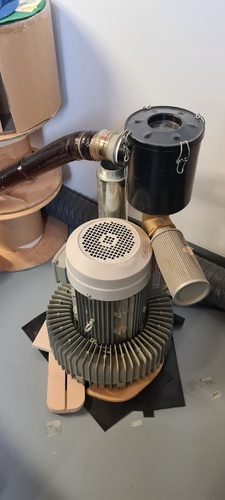
The machine is powered by raising the differential switches in the electrical panel on the wall — not from a button on the machine itself. The dust extractor is a separate unit that gets switched on just before pressing RUN.
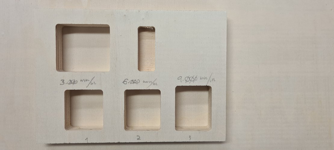
Feeds and speeds test.
Before cutting the actual project, Pablo ran a test to confirm that 9,000 mm/min — the lab standard for 6 mm single-flute on 18 mm plywood at 18,000 RPM — produces acceptable results. We cut three pockets at 3,000 / 6,000 / 9,000 mm/min and compared the wall finish.
The chip load formula for reference:
Feed rate (mm/min) = Chip load × flutes × RPMFor a 6 mm single-flute end mill on plywood, chip load range is 0.28–0.30 mm:
| Chip load | Calculated feed rate |
|---|---|
| 0.28 mm | 5,040 mm/min |
| 0.30 mm | 5,400 mm/min |
The lab default of 9,000 mm/min sits above the calculated range, but in practice the wall quality at all three speeds was indistinguishable on this material. No visible difference in surface finish, no burning, no chatter. 9,000 mm/min confirmed as the lab standard.
Full confirmed parameters:
| Parameter | Value |
|---|---|
| End mill | 6 mm, 1 flute, straight |
| Spindle speed | 18,000 RPM |
| Feed rate | 9,000 mm/min |
| Plunge rate | 1,500 mm/min |
| Pass depth | 10 mm max |
| Ramp angle | 30° (always enabled) |
| Cut depth | material thickness + 0.15 mm |
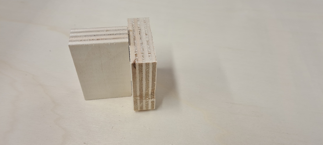
Joint test.
T-bone reliefs are required at every interior corner because a round end mill cannot cut a sharp 90° corner. The T-bone diameter is set equal to the end mill diameter — 6 mm in this case. I cut a test joint in the same material to verify fit before committing to the stool geometry. Slot width:
slot_width = measured_thickness + tolerance = 18.15 + 0.20 = 18.35 mm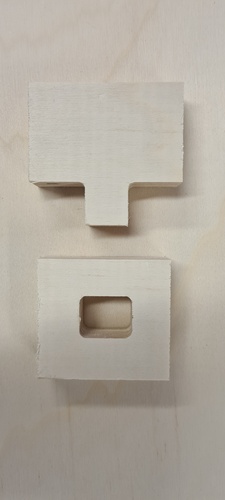

individual assignment.
A note on CAD.
I came into Fab Academy with no CAD background. None. My professional experience is in industrial automation which involves a lot of structured thinking but almost no 3D modelling. The closest I’d been to parametric design before this was laying out control panel schematics in AutoCAD.
Fusion 360 is, for me right now, all three things at once: a technical challenge I’m committed to overcoming, a tool I genuinely need for the final project (a height-adjustable standing desk with four synchronized actuators), and a source of real frustration when the software behaves in ways I don’t yet understand. The parametric workflow, the sketch constraints, the CAM environment — each of these is its own learning curve on top of the others.
This week was the first time I used Fusion for something that ended up physically cut in 18 mm plywood. That gap between the screen and the machine — where a wrong number becomes a miscut joint that can’t be undone — is what makes CAD feel high-stakes in a way that code doesn’t. I expect Fusion to be one of the hardest ongoing challenges of this programme. I’m not going to pretend otherwise.
Design concept — spiral 0.
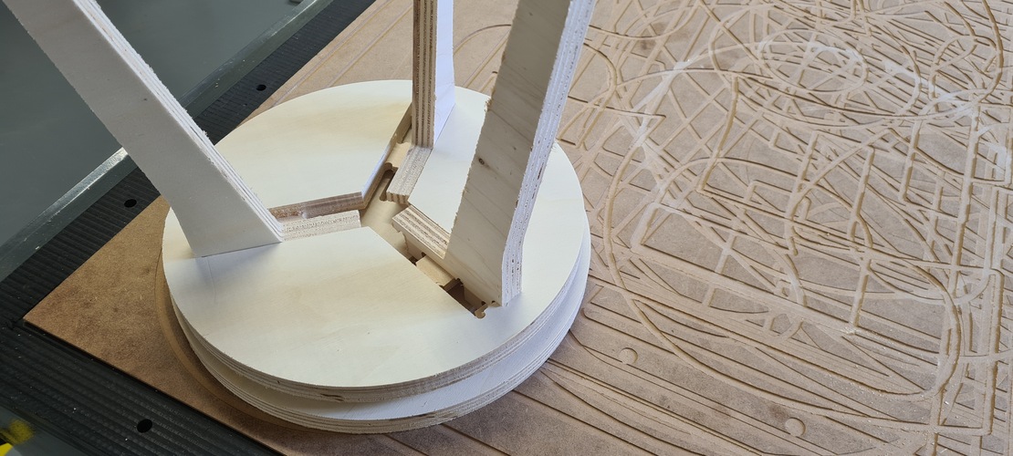
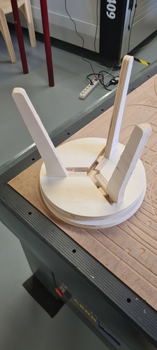
For spiral 0, Fab Lab León provided a reference design — a flat-pack stool using a cross-slot joint — as a starting point to gain familiarity with the CNC workflow without spending the first session fighting the CAD tool from scratch. The stool is the Edie Stool from Opendesk’s Edie Set, by David & Joni Steiner, shared as an open design for local CNC making. The concept: two identical pieces of plywood that cross-lock at 90° to form a stable seat at approximately 50 cm height. No fasteners. No glue. Assembly by hand. The cross-slot joint is the only connection mechanism.
Before committing to CNC time, I prototyped the concept at scale on the laser cutter. The laser doesn’t replicate the T-bone geometry — the kerf is essentially zero — but it was enough to validate the proportions and confirm the slot position and assembly logic.
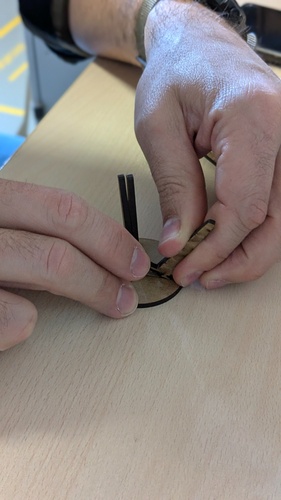
This is a workflow I’ll repeat: prototype fast on the laser, then move to CNC once the geometry is confirmed. It saves material, machine time, and avoids forcing oversized joints in 18 mm plywood.
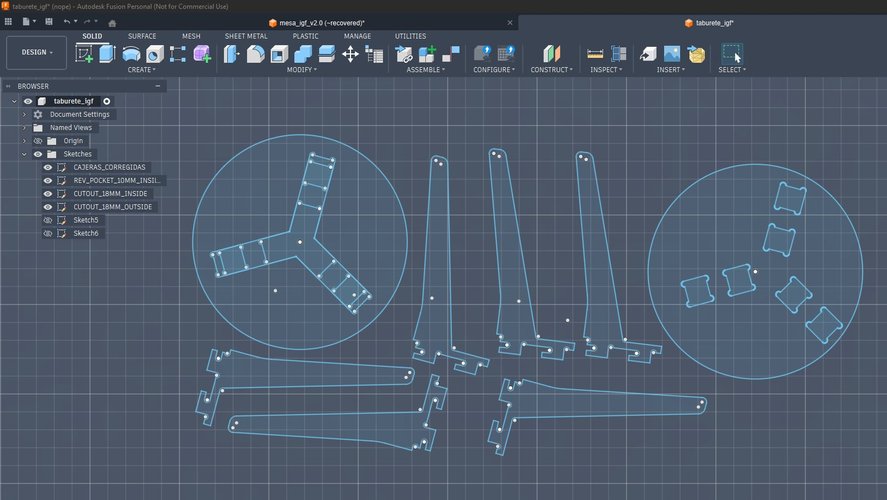
Design in Fusion 360 — spiral 0.
The Fusion 360 file provided by the lab contained the stool geometry as a set of sketches. Key parameters documented from the file:
| Parameter | Value | Notes |
|---|---|---|
board_thickness | 18.15 mm | Measured with calipers on the day |
slot_tolerance | 0.20 mm | Added to board_thickness for slot width |
slot_width | 18.35 mm | = board_thickness + slot_tolerance |
tbone_radius | 3 mm | = end_mill_diameter / 2 |
piece_height | 500 mm | Leg height |
piece_width | 380 mm | Seat width |
arc_radius | 60 mm | Inner leg corner cutout |
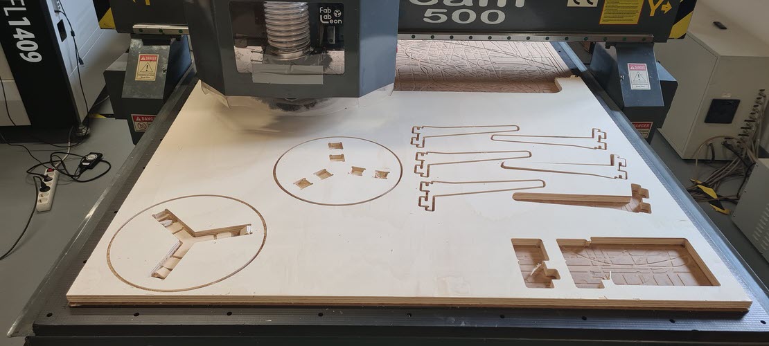
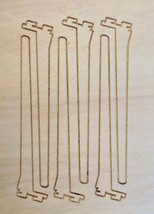
The design is two identical pieces. Each piece has: a rectangular cross-slot at mid-height, T-bone reliefs (⌀ 6 mm) at all four interior slot corners, curved cutouts (r = 60 mm) at the inner leg corners to reduce stress concentration, and 4 tabs per piece (8 × 3 mm) to keep pieces attached to the board during cutting.
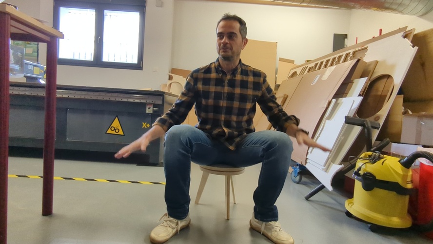
Note: Spiral 0 works — you can sit on it — but the slot tolerance was insufficient and the seat discs mismatched due to a scaling error in Aspire. Both issues fed directly into the spiral 1 redesign.
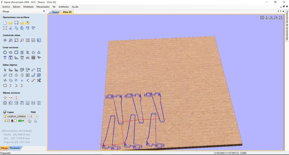
CAM setup in VCarve Aspire.
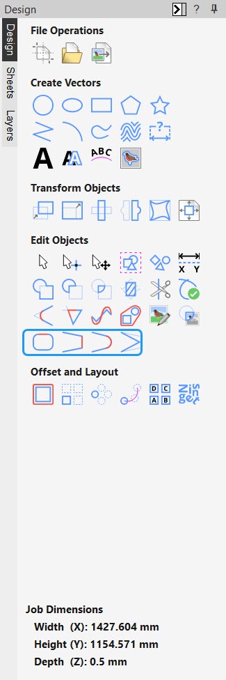
Before getting into the actual toolpath work, a quick walkthrough of the VCarve Aspire interface. The layout is organised around four main zones, and every operation this week happens in one of them:
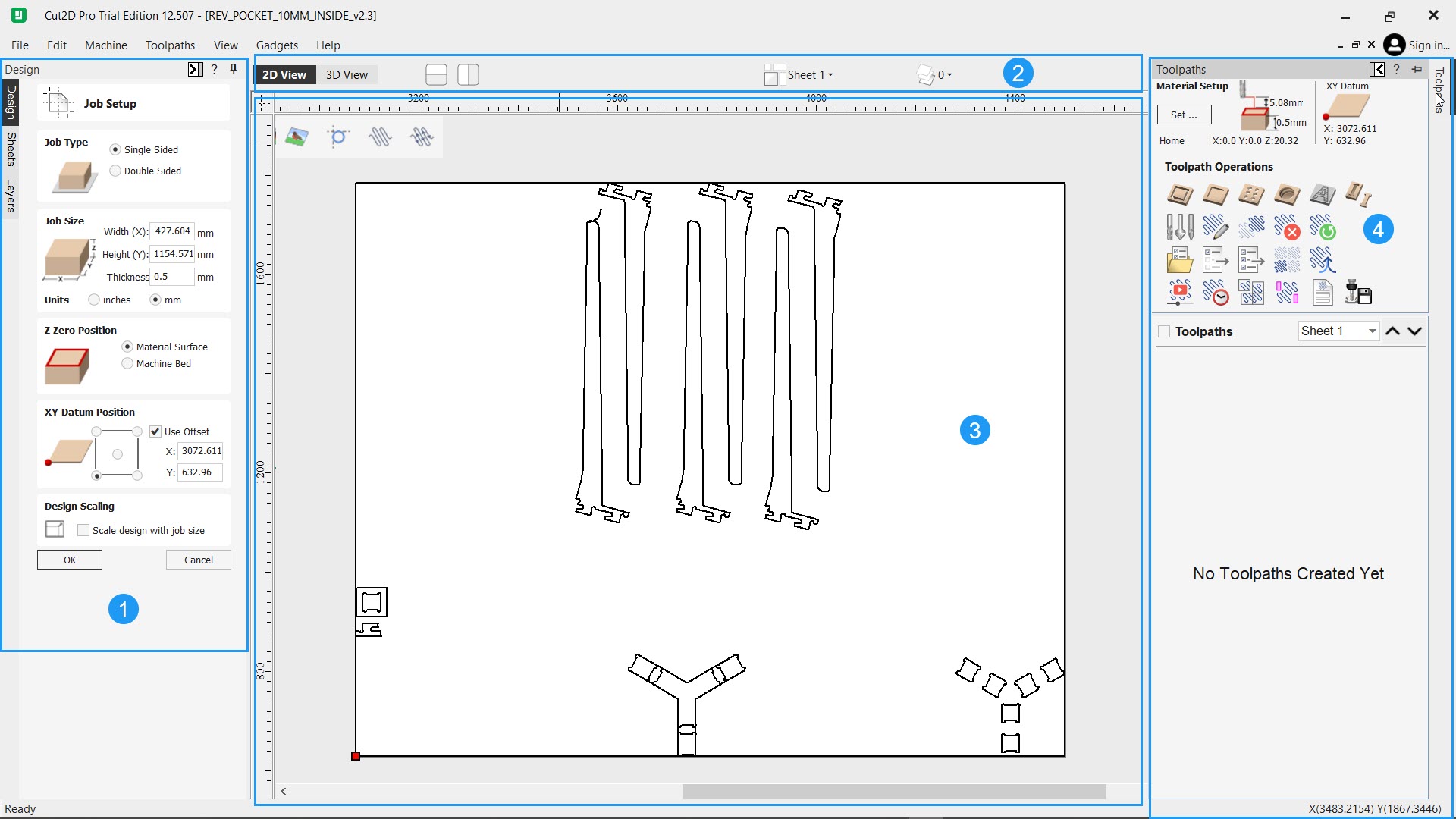
- Design side panel. Left-hand column where the drawing and editing tools live. The workshop you are working in is selected with the vertical tabs on the edge (Design, Sheets, Layers), and each one exposes a different set of tools. For this week everything happens inside the Design tab — creating and editing vectors, laying out pieces, preparing the geometry before it goes to CAM.
- View toolbar. Top strip that controls how the canvas is shown. Switches between 2D and 3D preview, toggles layer visibility, and exposes the display options for the main drawing area.
- Drawing canvas. The central area where the actual work is visible — imported vectors, layouts, toolpath previews and 3D simulations all render here.
- Toolpaths panel. Right-hand column, opened from the tab on the edge. This is the CAM side of the software: defining operations, assigning tools, previewing toolpaths and running the simulation before saving the
.TAPfile for the machine.
A note on software versions.The real job — the one that actually cut the plywood on the TEC-CAM 500 — was set up and post-processed in VCarve Aspire on the Fab Lab León laptop, using the “Fab León G-Code” postprocessor. The Cut2D Pro screenshots were captured afterwards on my own machine, only to re-document parts of the workflow more clearly; no Cut2D Pro file was ever sent to the machine. The interface and controls are practically identical between the two, so the steps shown apply equally to both.
Key things about Aspire that Pablo taught me during this session:
- Postprocessor: Always use “Fab León G-Code” — never change this.
- Material origin: Always bottom-left corner.
- Tool library: Never edit the base library entries — use “Edit” to adjust per-job.
- Toolpath order: Pockets → interior profiles → exterior profiles — cutting in any other order risks losing fixturing mid-job.
- Ramps: Always enable, 30° — prevents direct plunge, extends tool life.
- Critical bug: Aspire forgets the selected tool every time you reopen a toolpath dialog — always reselect before saving, even if it looks correct.
- File naming: Max 8 characters visible on the RichAuto display.
- Save workflow: Save to local disk first, then copy to pendrive — never save directly to pendrive.
Vector troubleshooting: When importing DXF from Fusion 360, open vectors prevent toolpath calculation. Fix: Join Vectors. If vectors are still open after joining, there are overlapping line segments — use the Trim tool to remove duplicates, then Join again. This cost about 20 minutes during my setup.
Final CAM parameters:
| Parameter | Value |
|---|---|
| Material | Plywood, 18.15 mm measured |
| End mill | 6 mm, 1 flute, straight |
| RPM | 18,000 |
| Feed rate | 9,000 mm/min |
| Plunge rate | 1,500 mm/min |
| Pass depth | 10 mm |
| Cut depth | 18.30 mm (18.15 + 0.15) |
| Tabs | 4 per piece, 8 × 3 mm |
| Output format | .TAP |
| Postprocessor | Fab León G-Code |
| Output files | PATAS.TAP, ASSUP.TAP, ASINF.TAP |
| Estimated cut time | 4 min 56 sec |
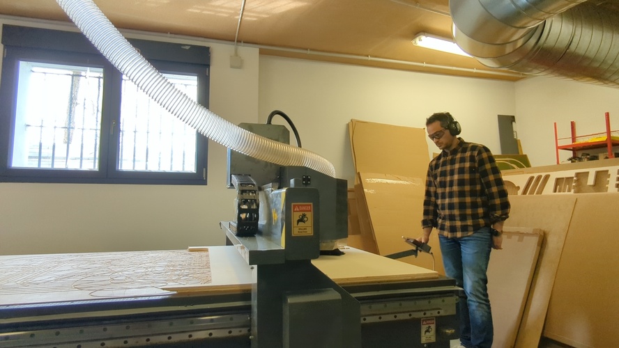
Machine operation.
Full startup sequence:
1.  Personal safety: tie hair back; remove loose items — belts, scarves, sleeves, jewellery.
2.  PPE: ear protection + safety glasses.
3.  Install end mill (machine off).
4.  Raise differential switches in the electrical panel.
5.  Controller: HOME → OK  (machine homes to reference position).
6.  Jog to XY origin (board bottom-left corner).
7.  Set 0 for X and Y axis (button XY→0).
8.  Activate vacuum pump.
9.  Z-probe: press first MENU → and once ON/OFF → probe lowers until contact → Z0 auto-set.
10. Activate dust extractor.
11. Load file: RUN/PAUSE DELETE → U DISK → select filename → OK.
12. RUN/PAUSE → verify spindle spinning → OK → job starts.
13. Stay at machine, hand near STOP/CANCEL.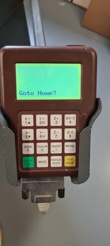
Sound is the main feedback during cutting. A consistent tone means everything is normal. Any sudden change — a crack, a pitch shift, a grinding noise — means stop immediately with STOP/CANCEL and assess before continuing.
Milling.
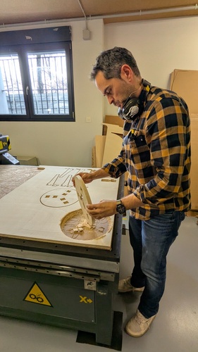
Assembly — spiral 0.
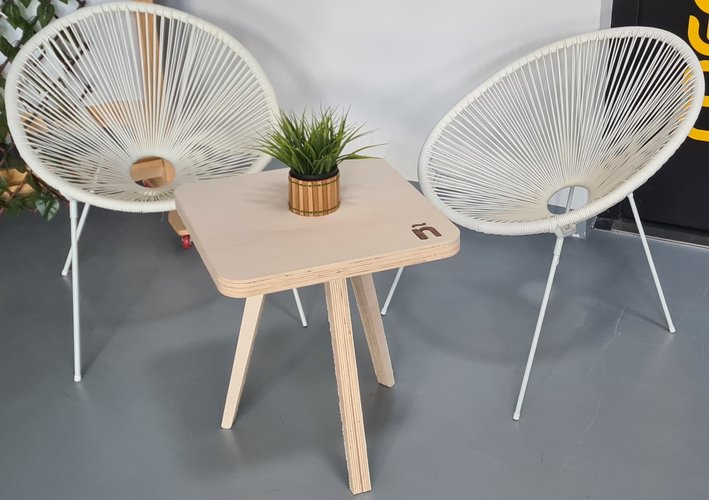
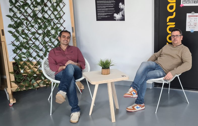
Spiral 1 — tea table.
The problems from spiral 0 were clear enough to act on the same week. Rather than re-cutting the stool with adjusted tolerances, I took the spiral 0 file as a starting point and redesigned it into something new: a low tea table with three legs in a Y configuration, a square top with rounded corners, and an engraved ñ on the surface.
Design in Fusion 360 — spiral 1.
Working from the spiral 0 file, I modified the geometry in Fusion 360 to create the tea table. The key changes were: replacing the two-piece cross-slot with a three-leg Y system, resizing the overall proportions for a lower table height, and adjusting the slot width to fix the tolerance problem from spiral 0.
All of this happened at sketch level: the spiral 0 file is a sketch-based DXF import with no parametric history, so there were no parameters to drive — only geometry to edit directly. I opened the existing sketches with Edit Sketch, used Trim and Delete to strip out the two-piece cross-slot, and drew the new three-leg Y layout with the Line and Rectangle tools, applying a Circular Pattern (three instances at 120°) to the Y-junction slots. Offset set the slot widths; Sketch Fillet rounded the four corners of the top panel; Move/Copy arranged the six leg pieces; and the ñ was built with the Text command, then turned into a pocket profile for engraving. The slot tolerance carried over from spiral 0 was corrected with the Scale tool on the slot elements — the scale factor was:
scale_factor = target_dimension / current_dimension
36.3 / 36.6 = 0.99180
Laser prototype first.
Before committing to CNC, I cut a quick laser prototype of the new joint geometry to validate the slot fit with the updated tolerance. The laser kerf is negligible compared to the CNC end mill, so the prototype doesn’t replicate the exact fit — but it’s fast and confirms the assembly logic and proportions before spending machine time on 18 mm plywood.
CAM setup for spiral 1.
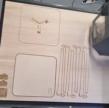
The same Aspire workflow as spiral 0, with the toolpath order strictly maintained: pockets first (the ñ engraving), then interior profiles (slot cutouts), then exterior profiles (leg and seat outlines).
The cut.
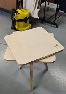
The joint fit was clean. Assembly by hand and the little help of a mallet. The table is stable under load. The ñ engraving came out sharp.
Finishing — top panel fit.
The first top panel didn’t fit. The DXF file carried geometry problems that weren’t obvious until assembly: the pocket layout for the three leg tenons assumed perfect symmetry across the Y configuration, but the actual cut geometry had subtle deviations from the DXF noise. We had been too trusting of the imported vectors.
Before re-cutting the top, I verified every pocket dimension individually against the physical leg tenons — not against the file. Once the pockets were confirmed correct, I re-cut the top panel. The fit was exact.
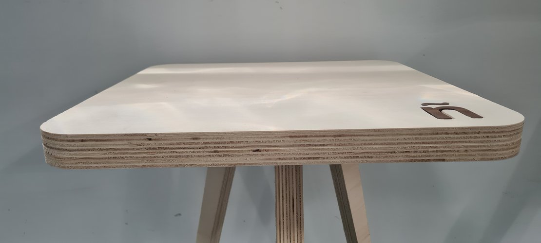
The ñ on the surface is not just an engraving pocket — it’s a laser-cut inlay in a different wood species, dropped into the CNC-cut recess. The contrast between the two materials makes it read clearly without needing paint or finish.
problems and solutions.
| Problem | What happened | Root cause | Resolution in spiral 1 |
|---|---|---|---|
| Slot too tight | Second piece would not enter the slot cleanly at 90° | Tolerance of 0.20 mm was insufficient; cut edge roughness and slight board variation add friction | Applied scale factor (0.99180) to slot geometry in Fusion; validated with laser prototype before CNC cut; assembly fit confirmed clean |
| Seat discs mismatched | The two circular discs forming the seat do not align — one overhangs the other | A scaling error during DXF manipulation in Aspire changed the dimensions of one piece relative to the other | Redesigned as tea table in spiral 1; verified all dimensions in Aspire before placing toolpaths |
| Open vectors from DXF import | Toolpath calculation failed on first import | Overlapping line segments at corners in the Fusion 360 DXF export | Trim overlapping lines in Aspire with the Trim tool, then Join Vectors; verify all contours are closed before assigning toolpaths |
| Top panel pockets misaligned | First top panel didn’t fit onto the leg tenons | DXF geometry noise — assumed symmetry that wasn’t actually there in the imported vectors | Verified every pocket dimension individually against the physical pieces before re-cutting; never trust the DXF without measurement |
what I learned.
The CNC is the machine that requires the most preparation before you touch it. By the time you press RUN, most decisions are already locked in — material thickness, tool selection, feed rates, joint tolerances, toolpath order. If any of those is wrong, the error shows up physically in wood, and you cannot undo a cut.
A few things I’m taking forward:
Prototype fast, prototype cheap. The 10-minute laser test was worth more than an hour of simulation in Aspire. I could hold the geometry in my hand and decide whether the concept was worth committing to CNC time. I’ll do this every time.
Tolerances are not guesses. The 0.20 mm tolerance I used was based on the joint test, not intuition. Even so, it wasn’t enough. Spiral 1 tests 0.35 mm and validates with a sample joint before cutting full pieces.
Sound is data. The machine communicates through the cutting sound. A consistent tone means everything is fine. An unexpected change — pitch, rhythm, crack — means stop and assess. I didn’t need this rule this week, but I know I will.
Aspire forgets things. The tool selection bug is real and non-obvious. Every time you reopen a toolpath dialog, verify the tool is still selected before saving.
DXF files lie. An imported DXF looks clean on screen but can carry invisible problems — open vectors, duplicated nodes, geometry that appears symmetric but isn’t. Never trust a DXF import without independently verifying the critical dimensions against the physical reality. The top panel re-cut this week cost one board and thirty minutes because we assumed the file was correct. Measure the pieces, not the vectors.
files.
Spiral 0 — stool.
The spiral 0 stool is the Edie Stool from Opendesk’s Edie Set, designed by David & Joni Steiner and shared as an open, locally-makable design under Opendesk’s Open Making model. Fab Lab León provided it as the starting reference for this week.
taburete.dxf— source 2D geometry (Opendesk Edie Stool).
Spiral 1 — tea table.
mesa_igf_v2.3.f3d— Fusion 360 source file (spiral 1, tea table).mesa_igf_v2.3.dxf— 2D fabrication geometry, exchange format (DXF).