This week is all about additive manufacturing and 3D scanning. The main challenge is designing and printing an object that could not be easily made with subtractive methods (like CNC milling) — so the design needs to have features like overhangs, nested parts, or print-in-place mechanisms. On top of that, we also get to play with 3D scanning tools to digitize a real object.
learning objectives.
Understand the advantages and limitations of 3D printing compared to subtractive manufacturing.
Apply design rules that take advantage of what additive manufacturing can do (overhangs, bridges, print-in-place, nested geometry).
Learn how to prepare a model for printing: slicing, supports, infill, layer height and all the parameters that affect the result.
Use 3D scanning technology to digitize a physical object and understand the clean-up process.
assignments.
Individual assignment:
Design, document and 3D print an object (small, few cm3, limited by printer time) that could not be easily made subtractively.
3D scan an object (and optionally print it).
Group assignment:
Test the design rules for your 3D printer(s).
Document your work on the group work page and reflect on your individual page what you learned about characteristics of your printer(s).
process.
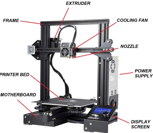
Parts of a 3D printer. Image source: [Techietory](https://techietory.com/3d-printing/anatomy-of-a-3d-printer-understanding-all-the-main-parts/).
3D printing (also called additive manufacturing) is a process where a physical object is built layer by layer from a digital model. Unlike subtractive methods like CNC milling — where we start with a solid block and remove material — here we start from nothing and add material only where it’s needed. The most common type for desktop use is FDM (Fused Deposition Modelling), which melts a plastic filament and deposits it through a nozzle, one layer at a time. This approach allows us to create geometries that would be impossible or very difficult to make with traditional manufacturing: internal cavities, overhangs, nested parts, or even mechanisms that come out of the printer already assembled.
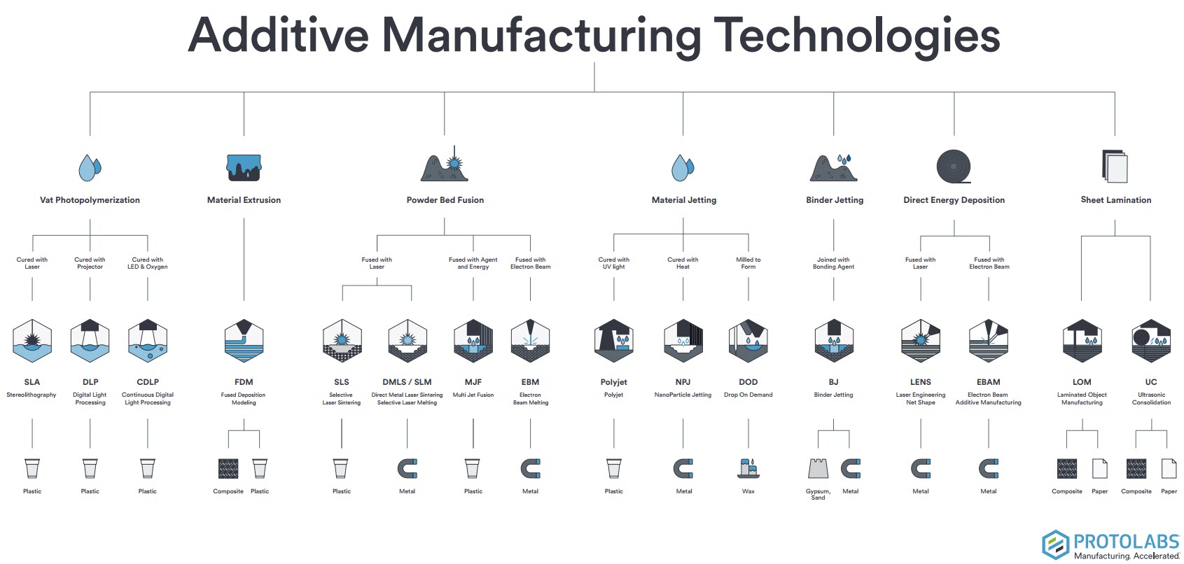
Additive manufacturing technologies, by [Protolabs](https://www.hubs.com/).
advantages and limitations of 3D printing.
Advantages: 3D printing lets us build complex geometries with almost no tooling — no moulds, no jigs, no setup costs. We can go from a digital file to a physical part in hours, which makes it great for prototyping and one-off pieces. Material waste is minimal compared to subtractive methods, and we can produce internal structures (like honeycomb infill) that would be impossible to machine.
Limitations: It’s slow for mass production — printing a single part can take hours. Layer-by-layer construction makes parts anisotropic (weaker along the Z axis), and surface finish is generally rougher than injection moulding or CNC. Material options are more limited, dimensional accuracy depends heavily on calibration, and some geometries still need support structures that leave marks when removed.
group assignment — test the design rules for your 3D printer(s).
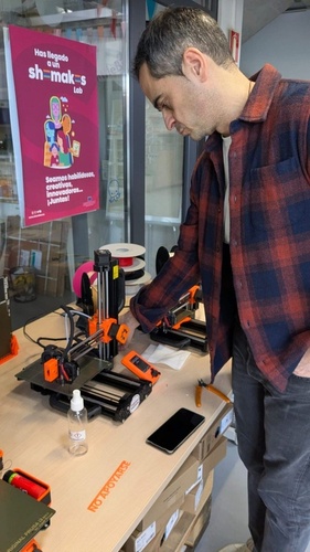
Let’s document the specifications of the two printers I will be working with in Fab León.
These are the safety rules posted at Fab Lab León, applicable to both printers:
For people:
Only one person should operate the machine at a time.
Never pull the power cable to disconnect — and never handle it with wet hands.
Do not put your hands in the extruder path — crushing hazard.
Do not touch the heated bed or the nozzle — burn hazard.
For the machine:
In case of emergency (smoke, unusual smell, abnormal noise, power cut), disconnect the power supply immediately and notify the Fab Lab manager.
Do not use the printer if anything seems off — burning smell, strange noise, smoke.
Cleaning and unclogging tasks must be done with the machine powered off.
Clean the build plate with isopropyl alcohol only — do not use hairspray.
Repairs and maintenance must be supervised by the Fab Lab manager, following the equipment manual.
Do not let metals or liquids come into contact with internal components.
Always clean the machine and workspace after use.
practical training.
So, after installing the Bambu Studio I received a brief introduction from Pablo, one of our local instructors. He walked me through the basic elements of the UI and then we prepare some of Neil’s printing examples.
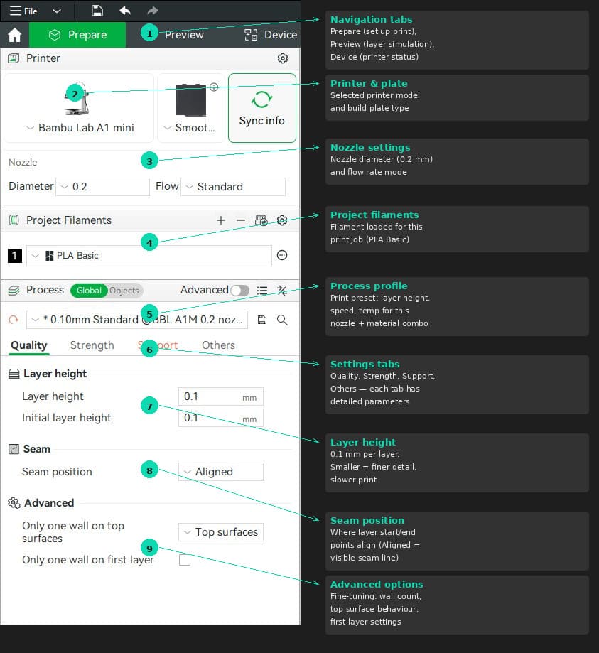
tab: Bambu Studio interface - Quality.
Bambu Studio — Prepare tab overview with key sections annotated.
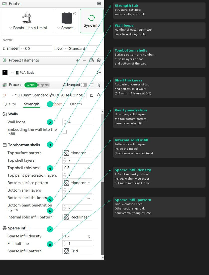
tab: Bambu Studio interface - Strengh.
Bambu Studio — Prepare tab overview with strength section annotated.
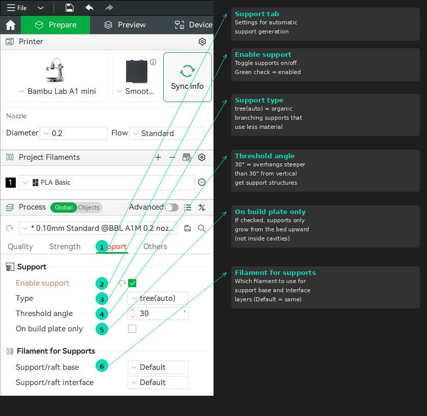
tab: Bambu Studio interface - Support.
Bambu Studio — Prepare tab overview with support section annotated.
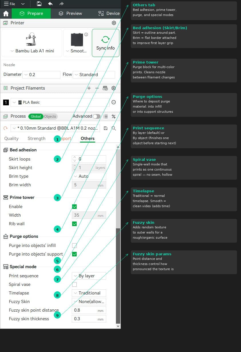
tab: Bambu Studio interface - Others.
Bambu Studio — Prepare tab overview with others section annotated.
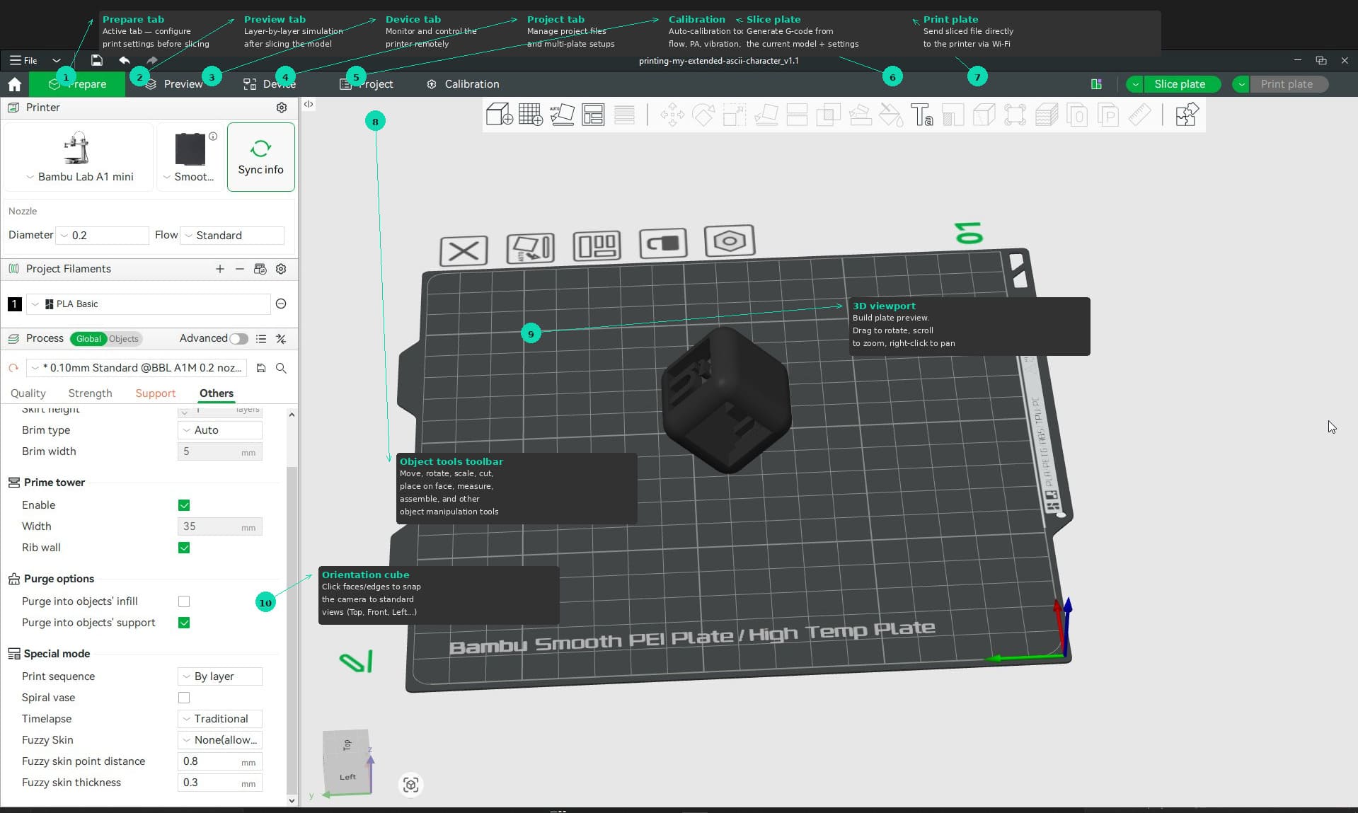
tab: Bambu Studio interface - Viewport.
Bambu Studio — Prepare tab overview with viewport section annotated.
tab: end
After that brief introduction, I took some notes on how to use of the Bambu A1 Mini.
Loading and unloading filament (Bambu A1 Mini).
This is the process Pablo showed us for swapping filament on the Bambu A1 Mini.
Loading:
Insert the Micro SD card face-down and power on the printer using the switch on the back.
Before inserting the filament, cut the tip at a 45° angle — this helps it slide through the tube more easily.
Go to Filament → Load on the touch screen.
The printer heats the nozzle to 250 °C (default temperature, enough to melt any common filament).
Feed the filament into the tube and push it gently until it stops.
The extruder motor will start pulling — you can feel it if you lightly touch the filament.
If you are not sure it grabbed, tap Retry and push a little more.
Once you feel the motor pulling, tap Ready.
The printer purges the remaining old filament through the nozzle until the new colour comes through.
Confirm when the new colour is flowing clean.
Unloading:
Go to Filament → Unload.
The printer heats the nozzle to 250 °C again — it needs to melt whatever is inside before pulling it out.
The machine cuts the filament internally using a small lever mechanism.
It then retracts the filament upward.
When prompted, pull the filament out gently — it should come out without resistance.
Some melted plastic may drip from the nozzle during this process — that is normal, the printer does not push it out, it just heats it and gravity does the rest.
Tips from Pablo:
Keep the filament spool oriented so it feeds from bottom to top — prevents tangles.
Keep the filament straight, do not let it twist on the way in.
The Bambu A1 Mini generates quite a lot of purge waste compared to other printers — that is just how it works.
Testing the Bambu A1 Mini.
As part of the group assignment, we tested the design rules of the Bambu A1 Mini using Neil’s test files. These are standardised STL models designed to push specific limits of FDM printers: overhang behaviour, angle tolerance, clearance between parts, and so on.
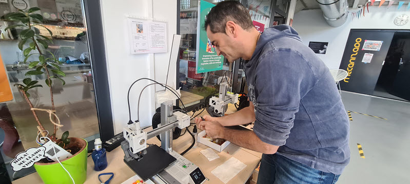
Printer preparation.
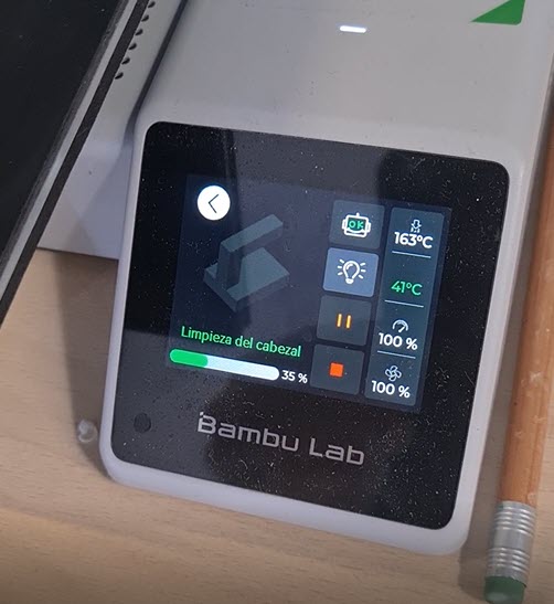
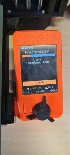
Before starting, the printer needed a nozzle cleanup and filament loading. The Bambu’s touch screen walks you through the whole process — heating the nozzle, purging old material, and confirming the new filament is flowing clean.
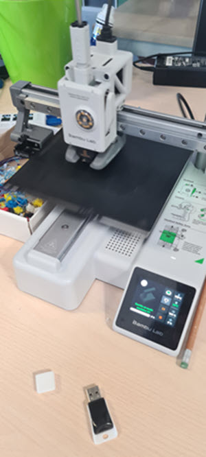
Loading PLA filament into the Bambu A1 Mini at Fab Lab León.Nozzle cleanup in progress — the screen shows hotend temperature (163 °C) and purge progress (35%).Bambu A1 Mini ready for the first test print. The small white piece from a previous job is still on the bed.
Angle test.
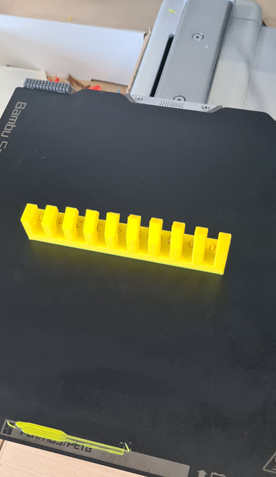
The angle test prints a series of vertical fins at increasing overhang angles — from 10° to 90° from vertical. This tells us at what point the printer starts struggling to print without support.
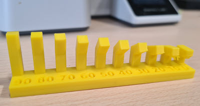
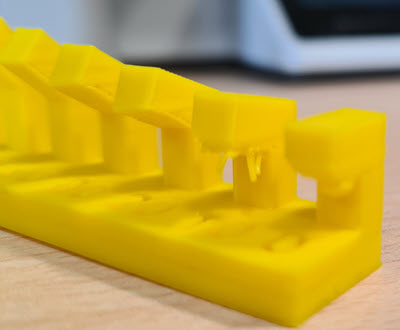
Angle test freshly printed in yellow PLA on the Bambu A1 Mini.Front view — each fin is labelled with its overhang angle (90° down to 10°).Side detail — the Bambu handles overhangs well all the way down to about 10° for this PLA filament. Beyond that, quality drops significantly.
Result: With this PLA filament and the default 0.1 mm layer height profile, the Bambu A1 Mini prints clean overhangs up to roughly 10° from horizontal. For what I have been reading, that is a very good result for a desktop FDM printer — most machines start showing defects around 30–45°.
Overhang test — with and without supports.
We printed Neil’s overhang test piece twice: once without supports and once with tree supports enabled. The goal was to see how much difference supports make on the final surface quality.
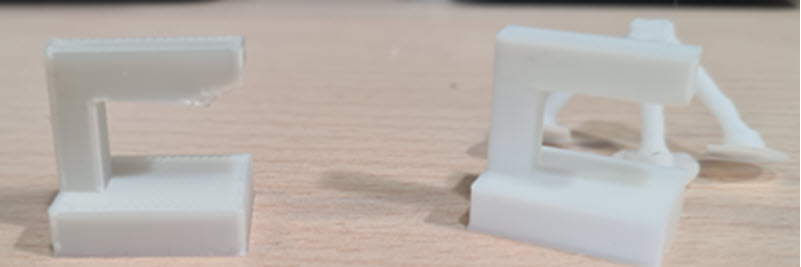
Without supports (left piece): The printer managed to complete the part, but the most extreme overhang section shows visible sagging and rough surface finish on the underside. The filament had nothing to land on, so it drooped before cooling.
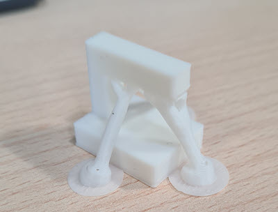
With tree supports (right piece): The organic tree supports held up the overhang during printing. After removing them, the surface underneath is noticeably cleaner and more consistent. The trade-off is the extra material, print time, and the cleanup work to remove the support structures.
Overhang test printed with tree supports — the organic branch structures are clearly visible before removal.Side-by-side comparison: without supports (left) shows imperfections on the overhanging section, while the supported version (right) has a cleaner finish after support removal.
First successful print.
After running the test files, it was time to see the result up close. The small test pieces came out well and gave us a solid understanding of what the Bambu A1 Mini can and cannot do.
First print of the day — examining the overhang test piece fresh off the printer.Removing the second test piece from the Bambu's PEI build plate.
What I learned from the Bambu A1 Mini
The auto-calibration (vibration, flow, bed leveling) runs before every print and really does make a difference — no manual tweaking needed.
Overhang performance is impressive: clean results down to ~10° from horizontal with PLA.
Tree supports work well for complex overhangs but generate a lot of waste material compared to standard supports.
The printer is fast — the angle test took around 40 minutes, which is noticeably quicker than the Prusa Mini+ for the same part.
First layer adhesion on the Smooth PEI plate was reliable without any glue or hairspray
Loading and unloading filament (Original Prusa Mini).
Likewise, I received a hands-on training for the Prusa Mini.
The process on the Prusa is slightly different from the Bambu — the extruder motor is separate from the hotend (Bowden setup), and navigation is done with a rotary knob instead of a touch screen.
Loading:
Go to Filament → Load Filament using the rotary knob.
Select the filament type (PLA, PETG, etc.) — the printer uses this to set the correct temperature.
The printer heats the nozzle to the target temperature.
Cut the filament tip at a 45° angle and feed it through the filament sensor from below (the spool feeds bottom to top).
Push the filament until it reaches the motor and stops — you will feel a slight resistance.
Press Continue — the extruder motor starts pulling the filament through the Bowden tube down to the hotend.
Unlike the Bambu, you do not need to keep pushing — the motor does the work once it grabs the filament.
The printer purges the old material. When asked if the colour looks correct, check the nozzle: if the new colour is not clean yet, select More to keep purging.
Once the colour is right, confirm and you are done.
Unloading:
Go to Filament → Unload Filament.
The printer remembers what filament is loaded — no need to select the type.
It heats the nozzle, then retracts the filament upward through the Bowden tube and out through the sensor.
Pull the filament out when prompted.
Differences from the Bambu A1 Mini:
The Prusa uses a Bowden extruder — the motor sits at the top, far from the nozzle, and pushes the filament through a tube. The Bambu has a direct drive where motor and nozzle are together
When you pull out a Prusa filament, you can see teeth marks (striations) left by the drive gear — that is normal.
Files are loaded via USB drive — no Wi-Fi connection on our unit.
Testing the Original Prusa Mini.
After the Bambu tests, it was time to move to the Original Prusa Mini+ — the lab’s other FDM printer. The workflow is quite different: no Wi-Fi, no auto-calibration, and a Bowden extruder instead of direct drive. Everything goes through a USB drive and the rotary knob on the LCD screen.
Getting ready to use the Original Prusa Mini at Fab Lab León.
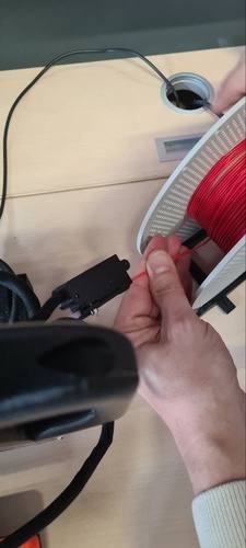
Filament loading The Prusa Mini uses a Bowden setup, so the filament feeds from the bottom of the machine through a sensor and then travels up a PTFE tube to reach the hotend. The process is menu-driven: you select the filament type (PLA in our case), the printer heats the nozzle to the right temperature, and then you push the filament into the sensor until the motor grabs it. Feeding the filament into the sensor at the bottom of the extruder — you push until the motor takes over.
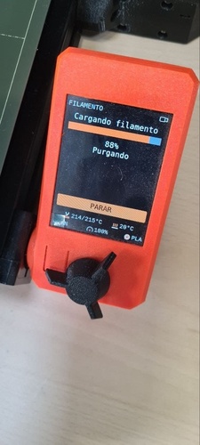
Once the motor pulls the filament through the Bowden tube, the screen shows the purging phase. The nozzle was already at 214 °C (target 215 °C for PLA) and the printer purged until the new filament colour came through clean.
Loading filament — 88% done, purging old material. Nozzle at 214/215 °C.
The unloading process is the reverse: the printer heats up, retracts the filament back through the Bowden tube, and you pull it out when prompted. The screen shows temperature and progress.
Unloading filament — heating to 215 °C and retracting through the Bowden tube.
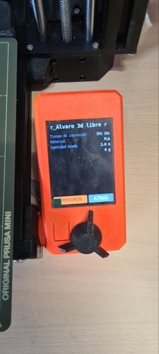
Starting a print With the G-code file on a USB drive, you plug it in, navigate with the rotary knob, and select the file. The screen shows a summary before printing: file name, estimated time, material type, filament length and weight. This is your last chance to review before committing.
Print summary — estimated time 37 min 19 s, PLA, 2.0 m of filament (6 g). Press IMPRIMIR to start.
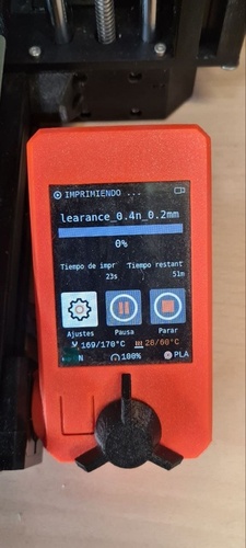
Once you confirm, the printer runs its bed leveling (SuperPINDA probe) and starts printing. The screen switches to the printing view with real-time progress, elapsed time, remaining time, and temperatures.
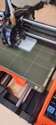
Printing clearance_0.4n_0.2mm — just started (0%), nozzle at 169/170 °C heating up, estimated 51 min remaining.The clearance test printing on the Prusa Mini — you can see the infill pattern being laid down layer by layer at 220 °C.
What I learned from the Prusa Mini
The Bowden extruder makes filament changes slower than the Bambu’s direct drive — the filament has to travel the full length of the PTFE tube in both directions.
No Wi-Fi on the lab unit means everything goes through USB. It is a simpler workflow in some ways: slice, export G-code, plug in, print.
The SuperPINDA probe handles bed leveling automatically, but the first layer is less forgiving than on the Bambu’s textured PEI plate — cleaning with isopropyl alcohol before each print really matters.
Print speed is noticeably slower than the Bambu A1 Mini for the same parts. The trade-off is that the Prusa is fully open-source and uses PrusaSlicer, which gives you more control over every parameter.
The rotary knob interface feels dated compared to a touch screen, but it works and there is nothing to break.
The orange LCD gives you all the essential information during printing: temperatures, progress, elapsed and remaining time. No camera, no timelapse — just the basics.
Slicing with PrusaSlicer.
Pablo walked me through preparing a print for the Prusa Mini+ using PrusaSlicer.
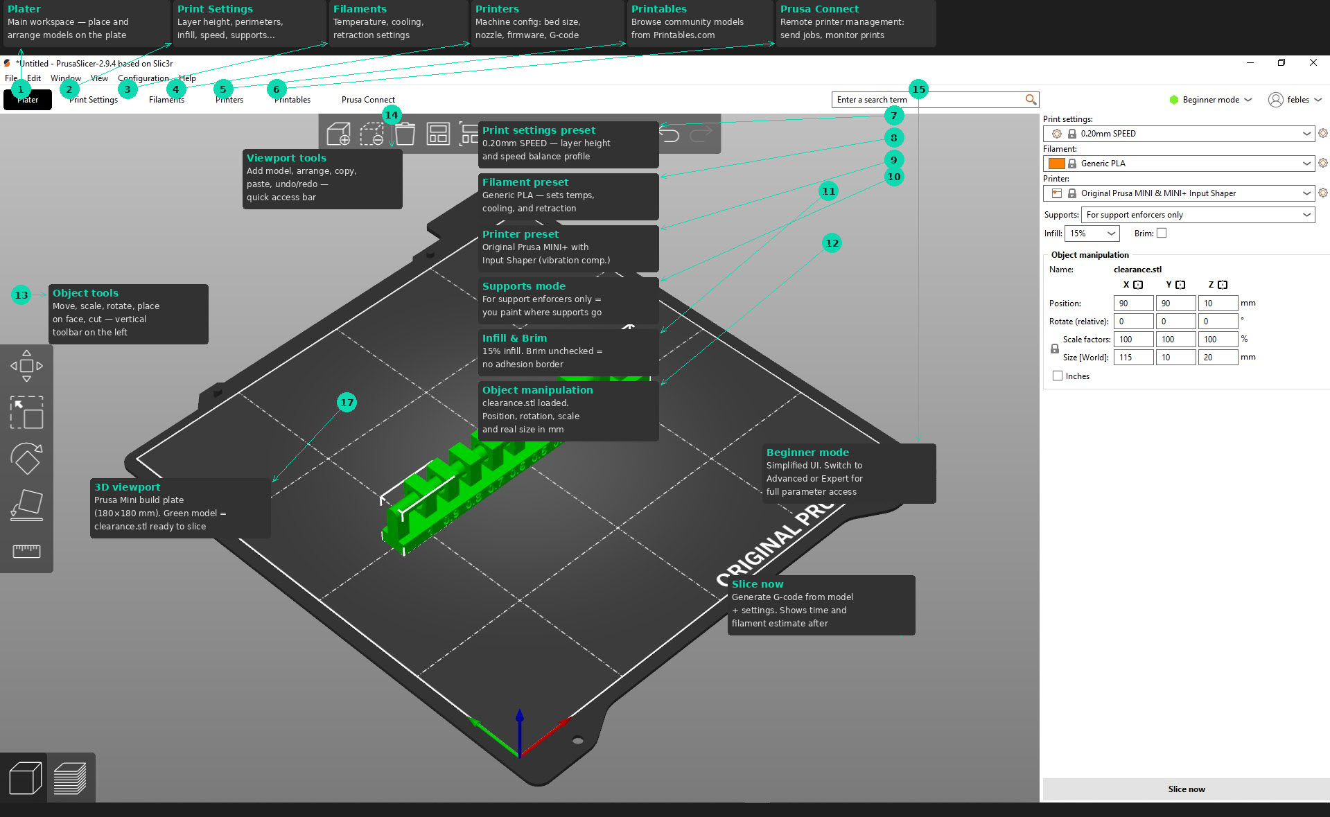
tab: PrusaSlicer interface - Viewport.
PrusaSlicer — Plater view with the clearance test model loaded and key interface sections annotated.
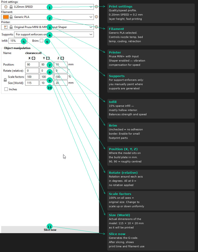
tab: PrusaSlicer right panel - settings.
PrusaSlicer — right panel: quick settings, object manipulation and slice button.
tab: end
Initial setup:
On first launch, the Configuration Wizard asks which printers you have — select Prusa FFF → Original Prusa Mini with a 0.4 mm nozzle
The printer profile comes preconfigured with all the mechanical parameters, so no manual tuning is needed
Preparing a print:
Click the cube + plus button to add a model (STL file)
At the top, select print quality — 0.2 mm layer height is the standard default. For smaller or more detailed parts, you can go lower
Set Infill percentage (how solid the inside of the part will be)
Configure Supports:
On build plate only — supports only grow from the bed surface up to overhangs (not inside the part)
Everywhere — supports are generated wherever needed, including inside cavities
For support enforcers only — you manually paint where you want supports using the paint tool
Brim/Raft/Skirt — for parts with a small contact area on the first layer, a brim adds a flat border to improve adhesion
Click Slice Now — the slicer shows a layer-by-layer preview with estimated time and filament usage
Export the G-code to your USB drive
G-code vs 3MF: PrusaSlicer exports .gcode files for the printer. The .3mf format is a project file that any slicer can open — Bambu Studio also uses 3MF, but with its own extensions. The raw G-code is plain text (machine movement commands) that you can inspect with any text editor.
individual assignment.
designing and printing a cube with ñ.
The individual assignment for this week was to design and 3D print an object that could not easily be made with subtractive manufacturing. I chose to design a hollow cube with the letter ñ floating inside — a character that carries special meaning as it is unique to the Spanish language and was also the subject of my first open-source contribution fixing extended ASCII character handling.
The ñ sitting inside the hollow cube, connected to the inner walls but visible from both sides, is something that would be impossible to machine on a CNC — the tool simply cannot reach inside to carve the letter from within a closed volume. This makes it a genuinely additive-only design.
Design process in Fusion 360
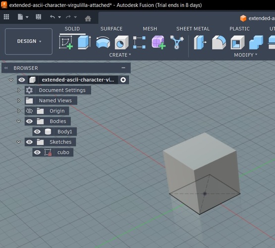
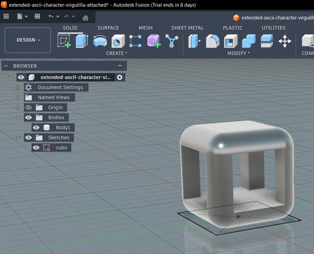
Step 1 — Solid cube. I started with a simple box sketch and extruded it into a 60 × 60 × 60 mm solid cube.
Starting point — a solid cube with only Body1 in the browser.
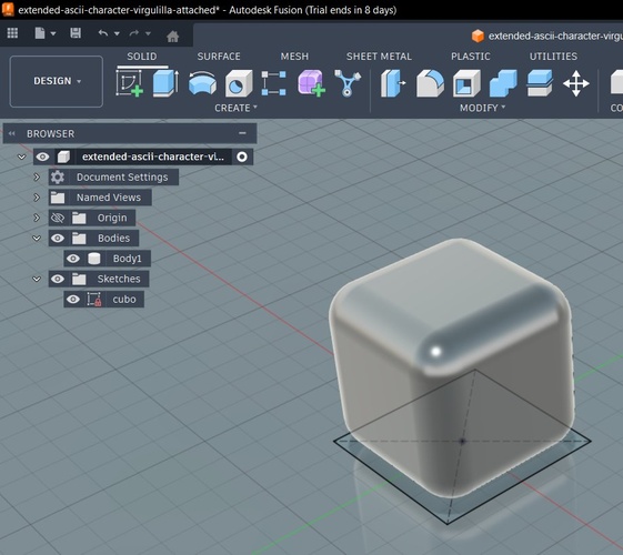
Step 2 — Chamfer/fillet the edges. I applied fillets to all edges to give the cube a softer, more organic look (Modify > Fillet, then select all edges and set the radius).
All edges filleted — the cube now has smooth, rounded corners.
Step 3 — Shell (hollow out). Using the Shell command (Modify > Shell), I selected the top and bottom faces to remove them, creating a hollow cube with uniform wall thickness. This left a top opening, a bottom opening, and the four side walls.
After Shell — the cube is now hollow with open top and bottom. You can see through it.
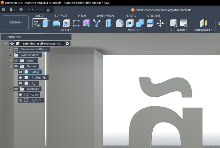
Step 4 — Add the ñ. I created a new sketch on one of the inner faces (Create > New Sketch, then select the face) and used the text tool (Create > Text) to place an ñ character. I then extruded the letter profile inward (Create > Extrude) so it sits inside the cube, resting on the bottom edge of the opening.
Close-up of the ñ — the virgulilla (tilde) and the n body are separate pieces in the Fusion browser. At this stage they are not yet connected.
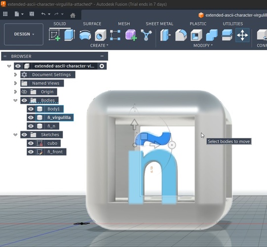
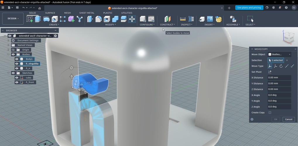
Step 5 — Mirror the ñ to the opposite face. To have the ñ visible from both sides of the cube, I needed to copy and rotate it 180° (Move/Copy under Modify > Move/Copy, with the Create Copy checkbox enabled). This is where I hit my first problem: in the Move/Copy dialog, the rotation handler was not appearing. It took me a while to realise this was a viewport issue — I was looking at the model from the front view, and the rotation axis I needed was perpendicular to that view. Once I switched to a 3D perspective, the handler appeared and I could rotate the copy 180° to place it on the opposite face.
The Move/Copy tool from the front view — the rotation ring for the axis I needed was not visible from this angle.The Move/Copy dialog with the ñ_virgulilla body selected. The Create Copy checkbox is key — it duplicates instead of moving. The rotation handlers only appear fully in a 3D perspective view.
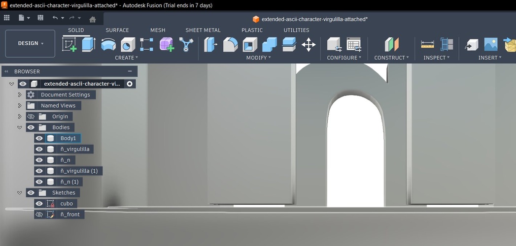
Step 6 — Connect the virgulilla. In most typefaces, the tilde (~) floats above the n with no physical connection. That is fine on screen, but in 3D printing it means the virgulilla has no support — it would just fall during printing. I fixed this by editing the ñ_front sketch and adding small rectangular bridges connecting the bottom of the virgulilla to the top of the n.
Virgulilla now physically connected to the n body through small bridge elements. This makes it printable without internal supports.
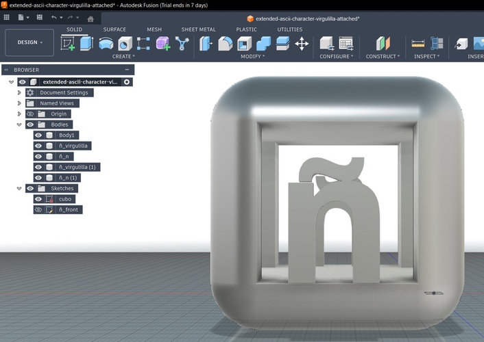
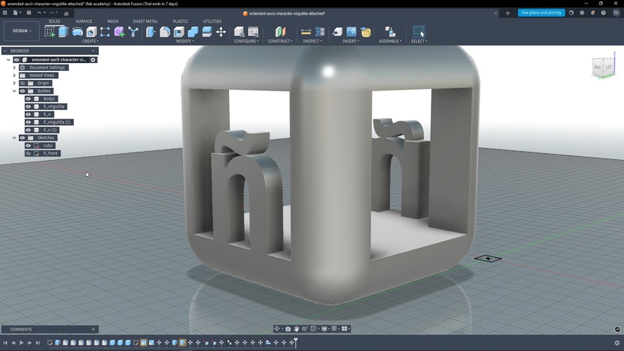
Final model. The completed design has the cube (Body1), plus the ñ components (ñ_virgulilla, ñ_n) on each face — five bodies total in the Fusion browser.
The final model — both ñ letters visible inside the hollow cube. The browser shows five separate bodies: cube, and two ñ components per face.Perspective view of the final model — both ñ letters visible inside the hollow cube, with the virgulilla properly connected. The browser shows all five bodies: Body1 (cube), ñ_virgulilla, ñ_n, ñ_virgulilla (1), and ñ_n (1).
First print — Prusa Mini (with mistakes)
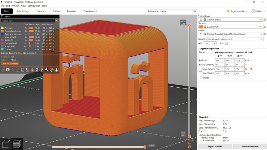
For the first attempt, I printed on the Prusa Mini using PrusaSlicer with the default upright orientation and no supports. I scaled the model to 75% (45 × 45 × 45 mm) to save time and material.
PrusaSlicer preview — the blue areas indicate overhang perimeters that have no support underneath. The print time estimate was 1 h 8 min, using 20.13 g of PLA.
Two problems showed up after printing:
The virgulilla fell off. In the first version of the model, I had not yet connected the virgulilla to the n body. Without that bridge, the tilde was just floating in mid-air — it printed as a separate loose piece and dropped when I removed the print from the bed.
No supports meant rough overhangs. Printing without supports saved material but the interior overhangs (the top of the ñ cavity, the inside of the hollow cube) came out rough with visible sagging.
First print result on the Prusa Mini — the ñ is visible but the virgulilla was not attached and fell off during removal. The brim is still visible at the base.
Second print — Bambu A1 Mini (with Pablo’s advice)
For the second attempt, I fixed the virgulilla connection in Fusion but accidentally moved the n body slightly upward, leaving a small gap between the base of the n and the bottom of the cube. This meant the ñ had no foundation — it was floating inside the cube with no contact to the floor.
Pablo pointed out something crucial when we reviewed the model in Bambu Studio: the blue-highlighted areas in the slicer preview indicate overhangs or floating geometry that needs support. According to the Bambu Lab wiki on support painting, when auto support is selected, areas within the threshold angle range are highlighted in a different colour. This visual feedback is your first warning that something may fail during printing — always check for unexpected blue zones before sending a job.
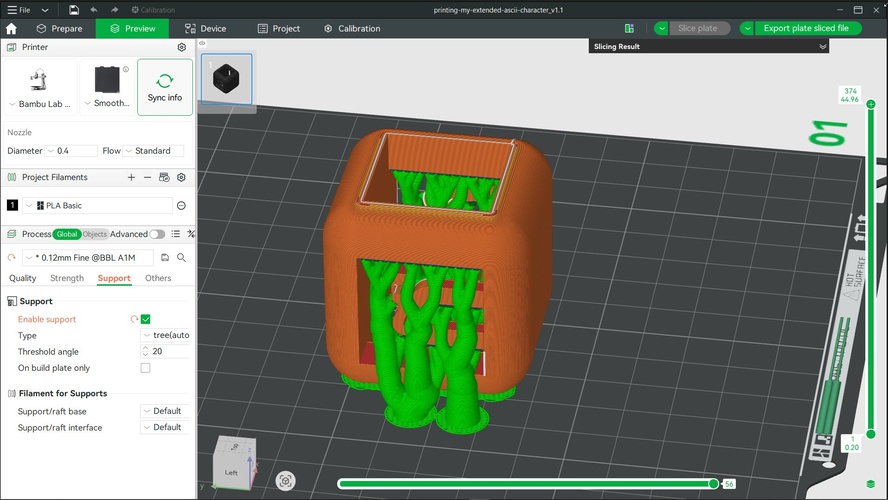
Pablo also showed me the optimal orientation for this particular model: instead of printing it upright (which creates massive overhangs on the top shell and the interior of the ñ), tilting the cube on its side dramatically reduces the amount of support material needed. The tree supports in this orientation are smaller and only needed for the letter geometry, not for the entire top face.
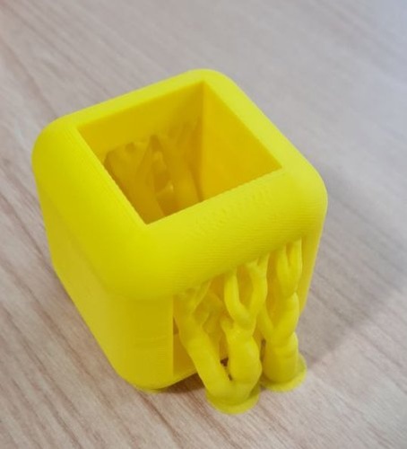
Bambu Studio with Pablo's suggested orientation — the cube is tilted so the open faces point sideways. Tree supports (green) are only needed for the letter overhangs, not the full top shell. Profile: 0.12mm Fine, threshold angle 20°.Second print result on the Bambu A1 Mini — yellow PLA with the optimised orientation. The tree supports are still attached, showing the branching structure that held the overhangs during printing.
Lessons learned
Always check the slicer preview for blue/highlighted zones before printing — they indicate unsupported overhangs or floating geometry.
Typeface characters are not print-ready by default. The virgulilla on the ñ floats in most fonts. For 3D printing, you need to add physical bridges connecting detached elements.
Orientation matters enormously. The same model can require 3× more support material simply by choosing the wrong print orientation. Tilt, rotate, and preview before committing.
Verify all bodies are connected in Fusion before exporting. A tiny gap between a body and the base (even 0.1 mm) means it has no foundation and will fail. The slicer will show it, but it is better to catch it in the CAD tool.
Iterate fast. The first print took over an hour and failed. The second attempt, with the right orientation and supports, used less material and produced a cleaner result.
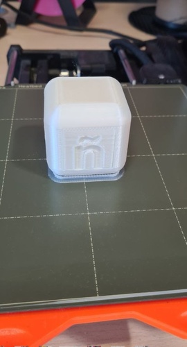
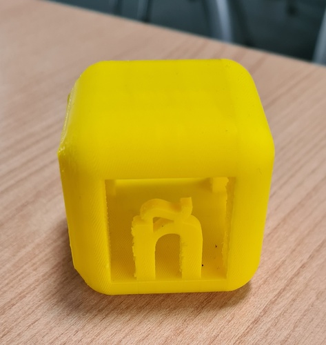
Final result after removing tree supports — the ñ is clearly visible inside the cube with the virgulilla properly connected. Printed in yellow PLA on the Bambu A1 Mini.
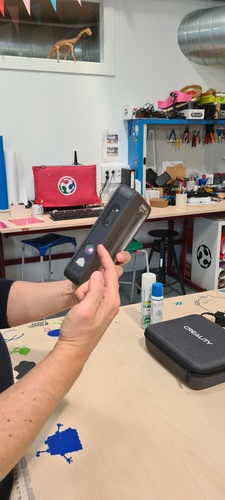
3D scanning with the 3D Sense scanner.
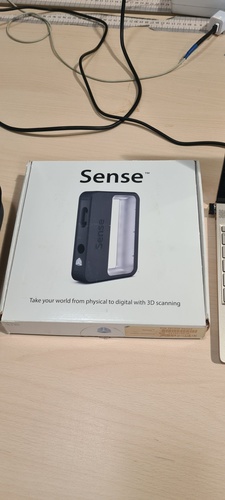
For the scanning assignment, we used the 3D Sense (also known as e-Sense) handheld scanner available at Fab Lab León. This is an older device (circa 2011) that is no longer commercially available, but it still works well for quick body scans and medium-sized objects.
The 3D Sense scanner — "Take your world from physical to digital with 3D scanning." No longer commercially available, the lab keeps a local copy of the software.
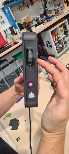
Hardware: The scanner has both infrared emitters/receivers and an RGB camera, so it captures geometry and colour at the same time. Some scanners only capture shape — this one gives you a coloured mesh.
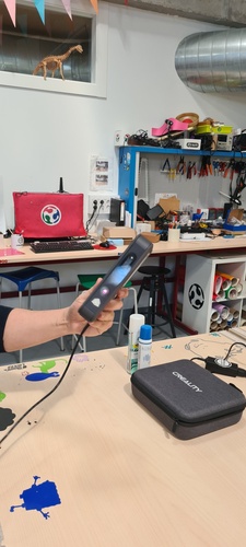
The Sense scanner powered on — compact and lightweight enough to move freely around the subject.Front detail — the IR emitter (bottom), RGB camera (centre), and depth sensor work together to capture both geometry and colour.
Software: It runs on a proprietary application also called 3D Sense. The software is no longer available for download, so our lab keeps a local copy installed. You need the scanner’s serial number to activate it.
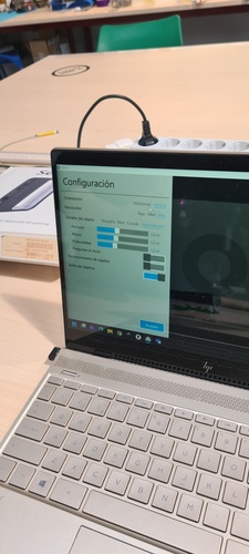
Setup and configuration:
Connect the scanner and launch the software.
Enter the scanner’s serial number when prompted.
Configure the scanning parameters:
Orientation: vertical or horizontal scanning mode.
Resolution: high, medium, or low (more data vs. faster processing).
Bounding box size: defines the capture volume around the object. The object must fit inside this box when you start scanning. For a person, roughly 1 × 1 × 2 m works. For smaller objects, reduce the box accordingly.
The bounding box size does not affect scan quality directly, but a larger box means more data for the computer to handle, and you are more likely to lose tracking.
Configuration screen — vertical orientation, high resolution, custom bounding box set to 1.3 × 1.2 × 1.2 m for a seated person scan.
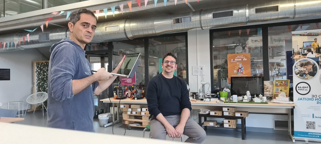
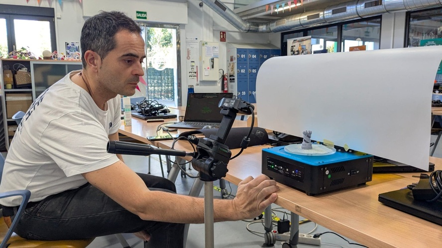
Scanning process:
Position the subject — they must stay completely still during the scan.
Start the scan from a position where the subject is visible and inside the bounding box.
Move the scanner slowly around the object, keeping a steady distance.
The software builds the 3D point cloud in real time as you move.
Do a full 360° pass at body level, then raise the scanner and do another pass from above to capture the top of the head.
If you move too fast or go outside the bounding box, the scanner loses tracking — just go back to your last position and it picks up again.
When done, hit Pause to stop capturing.
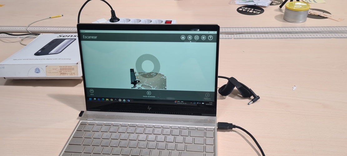
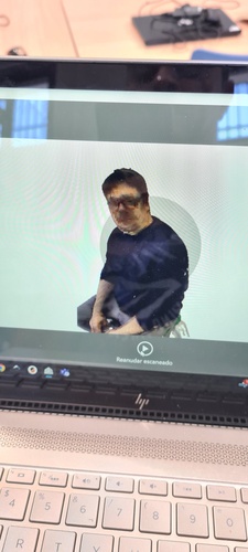
Scanning in progress — you move the Sense slowly around the subject while the software builds the point cloud in real time.The software showing the partial capture — the point cloud builds up as you orbit around the subject. The "Iniciar escaneado" button becomes "Pause" once scanning starts.Scanning session at Fab Lab León — I walk around Pablo with the laptop while he stays perfectly still.Scan result — the coloured mesh captured by the Sense. Note the glasses lenses are missing (transparent to IR) but the frames are visible. The "Reanudar escaneado" button lets you add more passes if needed.
Cleanup and solidification:
After scanning, the software shows the raw captured data — point cloud with stray points, floor fragments, and noise.
Use the Trim tool to remove unwanted parts (floor, background objects, floating points). Note: the trim tool keeps what you select, not what you might expect — it is the opposite of “delete selection.”
Use the Erase tool to manually remove stray point clusters floating in space.
Once the mesh is clean, hit Solidify — this fills in the gaps the scanner could not capture (back of the head, underside, etc.) and creates a closed, watertight mesh.
You can repeat the process: erase more, solidify again, until you are happy with the result.
The solidified model can be further cleaned up in Blender or Meshmixer if needed.
Export formats:
STL — geometry only, no colour.
OBJ — geometry + colour data (larger file size).
PLY and VRML are also available.
For Fab Academy documentation, the scanned file does not need to be uploaded to the repository (it can be very large). Screenshots of the process and result are enough. Optionally, you can upload the model to Sketchfab and embed the viewer in your page.
Tips for better scans:
Lighting is critical. Use uniform, diffused light with no strong shadows. Overcast/cloudy days are ideal for outdoor scans because light is even from all directions. A directional light source creates shadows that confuse the scanner — it interprets shadow boundaries as different surface points.
Transparent objects cannot be scanned with this type of sensor. The infrared beam passes through glass, clear plastic, etc. instead of bouncing back — so the scanner sees nothing there. Same problem with glasses on a person: the frames show up, but the lenses disappear.
Highly reflective surfaces (polished metal, glossy paint) also cause problems because the light scatters unpredictably instead of returning to the sensor.
The fix: professionals use a matte grey scanning spray (approx. €100/can) that coats the surface uniformly. Pablo showed us that dry shampoo from the supermarket (approx. €5) works as a budget alternative — it leaves a matte white coating that disappears after a few minutes. Not as precise, but perfectly functional for our purposes.
3D scanning with the Creality CR-Scan Ferret Pro.
We also tried the Creality CR-Scan Ferret Pro, a newer portable scanner that connects to a smartphone via Wi-Fi or direct USB-C cable.
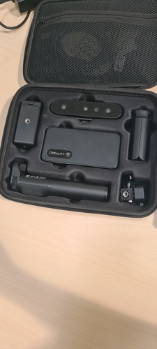
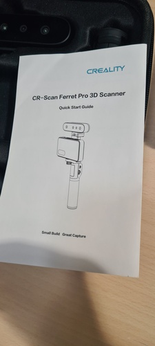
The Ferret Pro kit — scanner, Wi-Fi bridge, tripod grip, phone clamp, and accessories all in a compact carrying case.Quick Start Guide showing the assembled rig: scanner on top, phone in the clamp, tripod grip at the bottom.
Hardware setup:
The scanner mounts on a tripod handle with a phone holder. The full assembly is: tripod grip → phone clamp → scanner on top. It has a wireless bridge (generates its own Wi-Fi network called “Ferret”) and runs on a built-in battery.
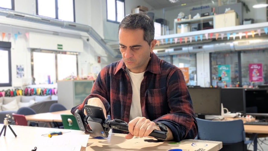
We had some trouble getting the wireless connection to work — the Wi-Fi bridge was not powering the scanner reliably. The solution was to skip the wireless bridge entirely and connect the scanner directly to the phone via USB-C cable. That worked immediately.
Assembling the Ferret rig — phone mounted in the clamp, scanner on top, connected via USB-C since the Wi-Fi bridge was unreliable.
Software: The scanner uses the Creality Scan app on the phone.
The hardware compatibility problem: Both my phone and my laptop were flagged by the Creality Scan app as having insufficient hardware for a good scan. The app runs a performance check before scanning and reported that neither device met the recommended specifications. We proceeded anyway, but the results reflected this limitation — laggy previews, frequent tracking loss, and lower mesh quality than expected.
Configuration:
Scan mode: Blue laser (high accuracy, requires tracking markers) or Red laser (marker-free, geometry-based tracking). We used geometry mode since our object had enough distinct features.
Target size: Small / Medium / Large — we set it to Medium.
Quality: High.
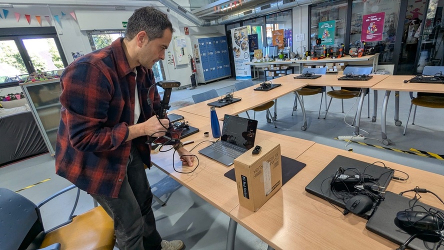
Turntable scanning attempt.
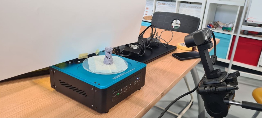
We set up a more controlled scanning environment using a photography tripod to hold the Ferret steady and an Elegoo 3D printing wash & cure turntable to rotate the object automatically. A white cardboard sheet behind the object provided a clean background to help with lighting and tracking.
The turntable setup — Elegoo wash & cure station rotating the object, white cardboard background for even lighting, and the Ferret mounted on a tripod pointing at the subject.Running the turntable scan — the idea was to let the object rotate while the scanner stayed fixed. A solid concept, but my laptop struggled to keep up with the data stream.
It was a creative setup, but my laptop could not handle the processing in real time. We also looked for an option in Creality Scan to tell the software we were using a turntable (so it would know the scanner was stationary and only the object was rotating), but we could not find one. The scan kept losing tracking because the software assumed the scanner was moving.
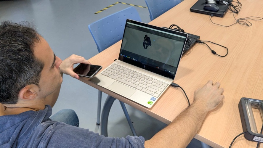
Handheld scanning attempt.
We also tried handheld scanning, walking around the object with the Ferret connected to the laptop.
Trying handheld mode — walking around the subject with the Ferret connected to the laptop via USB-C.Reviewing the scan result — the mesh was captured but with noticeable gaps and noise due to the hardware limitations.
The result was generally unsatisfying. Between the hardware warnings, the Wi-Fi bridge issues, the firmware update interrupts, and the “Scanner image transmission error” that required restarting the app multiple times, the Ferret experience was far more frustrating than the older 3D Sense.
What cannot be scanned (same principles as the 3D Sense):
Transparent objects (glass, clear plastic) — the laser passes through.
Highly reflective or shiny surfaces — the laser scatters unpredictably.
Very small, featureless objects (coins, keys) without prior surface treatment.
The recommended solution is scanning spray or, as Pablo showed us, dry shampoo as a budget alternative.
Tips from our session:
The app checks your phone’s performance before scanning — older phones may get a “not recommended” warning due to lag, but it can still work.
The scanner had firmware update prompts that interrupted the workflow — worth updating beforehand if possible.
We ran into a “Scanner image transmission error” that required restarting the app a couple of times before it stabilised.
If your hardware is below spec, the 3D Sense (despite being much older) may give better results simply because it offloads less processing to the host device.
photogrammetry with Polycam (mobile app).
As a final scanning exercise, Pablo suggested I try Polycam — a mobile photogrammetry app that reconstructs 3D models from regular phone photos. Unlike the dedicated scanners we used before, this runs on any recent smartphone with no extra hardware.
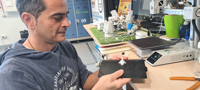
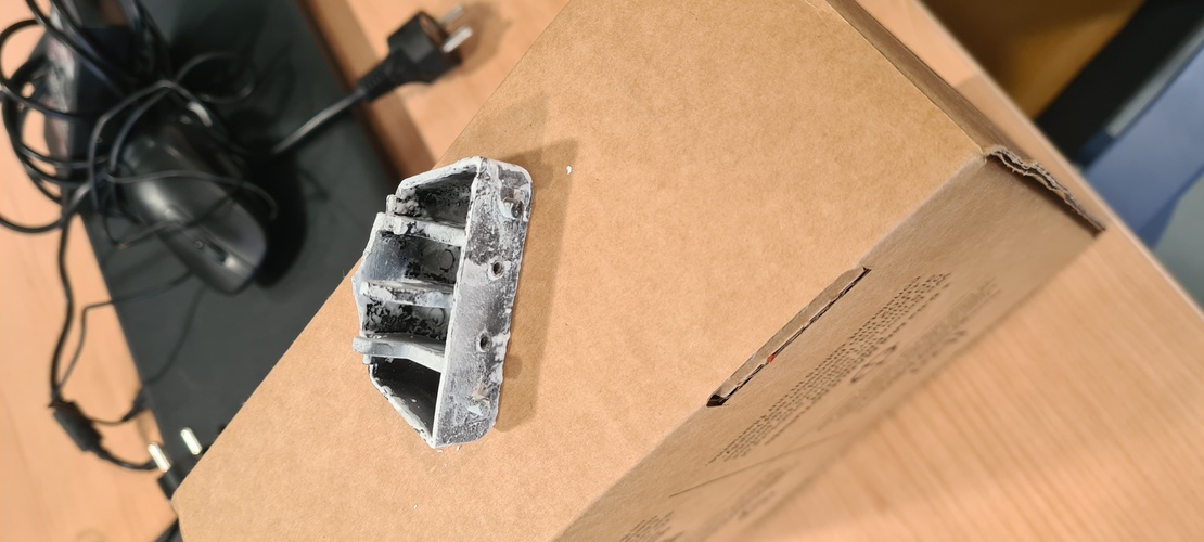
The object I chose to scan was a small plastic part that holds the lid of a bathroom bin. The part is broken and I have the personal goal of eventually reaching a good enough level in Fusion 360 to either scan-and-repair or redesign it from scratch and 3D print a replacement.
The broken bin lid hinge — a small part that would be a perfect candidate for a scan-to-print replacement.
Capture.
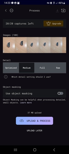
I used Polycam’s auto mode and took about 100 photos walking around the object from all angles — that was roughly the range where the app considered the capture optimal. The part was sitting on a table on one of its faces while I orbited it.
Polycam's processing screen — 100 photos captured. You can choose the detail level and toggle object masking.
The app offers four detail presets for cloud processing:
Level
Geometry
Textures
Maps included
Best for
Optimized
Low
Low
AO, Normal
Game engines, Web
Medium
Medium
Medium
AO, Normal
Game engines, iOS/Mobile
Full
High
High
AO, Normal, Roughness
Rendering / VFX
Raw
Highest
Highest
Albedo only
Professional workflows
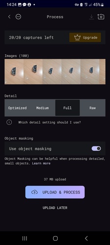
I processed at Full detail with Object masking enabled, since the part is small and detailed and I wanted the best geometry possible.
Final settings — Full detail, object masking on, 37 MB upload to Polycam's cloud for processing.
Result and post-processing.
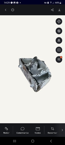
The scan result looked quite good visually — the general shape and internal compartments were clearly captured.
The reconstructed 3D model in Polycam's viewer — geometry and textures look solid for a phone-based scan.
Pablo suggested I export it to STL and check it in a slicer to verify the mesh was watertight. Here is where things got complicated:
Export limitation. The free version of Polycam only exports to .glb format — no STL option without a paid subscription.
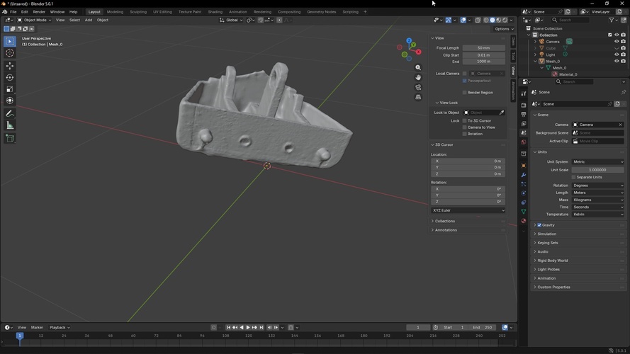
Conversion through Blender. I found that the way to go from .glb to .stl was through Blender. I imported the .glb, checked the scale (which was wrong and needed correcting), did a visual inspection of the mesh, and exported to STL.
The .glb model imported into Blender — I checked the scale (Units panel on the right) and did a visual inspection before exporting to STL.
Mesh errors in Bambu Studio. When I opened the STL in Bambu Studio, the slicer flagged incomplete geometry — despite looking like a closed solid, the mesh was missing triangles and was not watertight.
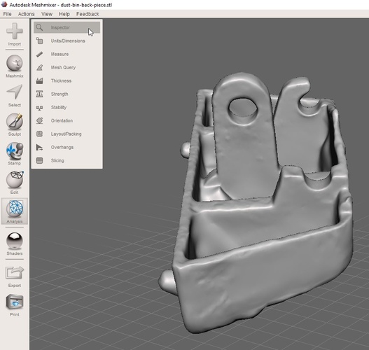
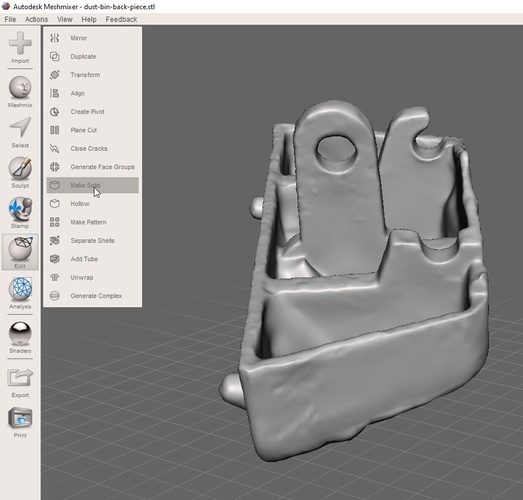
Repair with Meshmixer. Pablo suggested using Meshmixer (Autodesk) to fix the mesh. The workflow was: Analysis > Inspector to identify the holes and problem areas, then Edit > Make Solid to generate a clean, watertight mesh.
Meshmixer — Analysis > Inspector identifies holes and non-manifold edges in the mesh.Meshmixer — Edit > Make Solid generates a clean, watertight mesh from the inspected geometry.
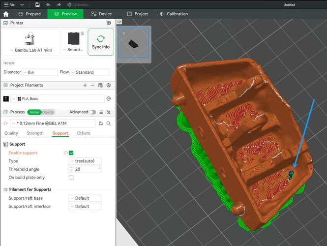
Final check. After exporting the repaired mesh back to STL and reopening it in Bambu Studio, the result was significantly better. A couple of tiny holes remained — Pablo explained these were likely spots where the original scan produced such a thin wall that the software did not recognise it as a surface during polygon generation.
The repaired mesh in Bambu Studio — tree supports (green) are generated for the overhangs. The white spots (blue arrow) indicate small remaining holes where the scan produced walls too thin to be recognised as solid surfaces.
Reflections.
For a free app that runs on a regular phone (mine is three or four years old, nothing special), the result was impressive. I have no idea how much better the paid version is, but the free tier already gave me a usable 3D model from just walking around an object with my camera.
The main limitation is that scanned surfaces are not geometrically regular. The reconstructed faces are organic and bumpy — they do not match the flat, perpendicular surfaces of the original manufactured part. This means that to actually produce a functional replacement, I see two paths: either spend hours in Blender cleaning up the mesh and making surfaces rectilinear, or skip the scan altogether and go straight to Fusion 360 with a calliper, measure every dimension of the original part, and model it from scratch. For a simple mechanical part like this one, the second option is probably faster and more accurate.
reflection.
This week was my actual first contact with 3D printing. Despite having been curious about it for years, I had never printed anything — the learning curve of CAD software always felt like too high a barrier to entry. Designing the cube with ñ in Fusion 360, iterating through failed prints, and finally getting a clean result gave me the confidence that this is something I can actually learn. I hope the Fab Academy programme helps me push past that initial discomfort and get to a point where I can reach for Fusion and a printer as naturally as I would for any other tool.
On the printing side, the contrast between the Prusa Mini and the Bambu A1 Mini was eye-opening. The Prusa felt more hands-on and educational — you understand every step because you are doing it manually. The Bambu felt more like a production tool — fast, automated, and forgiving. Both have their place, and I am glad I got to use both in the same week.
The scanning experience was more mixed. The dedicated scanners (3D Sense and Creality Ferret) were interesting to try, but neither felt like something I would reach for on my own — the hardware requirements, software quirks, and setup friction made the process less rewarding than I expected. The exception was Polycam: a free phone app that produced a genuinely useful 3D model with no special hardware and minimal effort. The fact that I can walk around an object with my phone and get a printable mesh (after some cleanup in Blender and Meshmixer) feels like the most practical takeaway from the scanning exercises.
If I had to summarise the week in one lesson, it would be something Pablo keeps reminding us: always design with the manufacturing process in mind. It is not enough to create a shape that looks right on screen — you need to think about how the machine will build it layer by layer, where the overhangs will be, what needs support, and what orientation will minimise problems. The same model can succeed or fail depending on how you place it on the build plate, and the fastest path to a good print is to print, fail, understand why, and print again.