Embedded programming
weekly schedule
| Time block | Wed | Thu | Fri | Sat | Sun | Mon | Tue | Wed |
|---|---|---|---|---|---|---|---|---|
| Global class | 3 h | |||||||
| Local class | 1 h | 1 h | ||||||
| Research | 2 h | 2 h | 1 h | |||||
| Design / coding | 1 h | 2 h | 3 h | 2 h | ||||
| Fabrication | ||||||||
| Documentation | 2 h | 2 h | 3 h | 3 h | ||||
| Review |
overview
This week focuses on embedded programming: reading microcontroller datasheets, understanding toolchains, and writing code that makes a board interact with input/output devices and communicate with the outside world.
learning objectives
- Read and extract relevant information from a microcontroller datasheet.
- Set up a development environment and toolchain for an embedded platform.
- Write, compile, upload, and debug programs for a microcontroller.
- Implement interaction with local I/O devices (sensors, displays, LEDs).
- Establish communication via wired or wireless connections.
assignments
Individual assignment:
-
browse through the datasheet for a microcontroller.
-
write and test a program for an embedded system using a microcontroller to interact (with input &/or output devices) and communicate (with wired or wireless connections).
-
extra credit: assemble the system.
-
extra credit: try different languages &/or development environments.
Group assignment:
- demonstrate and compare the toolchains and development workflows for available embedded architectures.
browse through the datasheet for a microcontroller.
For this assignment I chose the advised RP2040 datasheet. Considering the extension of this document I assigned 1 hour for the its review, split in 6 thematic blocks of 10 minutes. Here some of my thoughts:
Love the first sentences in their introduction:
Microcontrollers connect the world of software to the world of hardware.They allow developers to write software which interacts with the physical world in the same deterministic, cycle-accurate manner as digital logic. They occupy the bottom left corner of the price/performance space, outselling their more powerful brethren by a factor of ten to one. They are the workhorses that power the digital transformation of our world.
These are the main features:
Features:RP2040 is a low-cost, high-performance microcontroller device with flexible digital interfaces. Key features:
- Dual Cortex M0+ processor cores, up to 133MHz (or 200MHz at 1.15V).
- 264kB of embedded SRAM in 6 banks.
- 30 multifunction GPIO.
- 6 dedicated IO for SPI Flash [supporting XIP (Execute In Place)].
- Dedicated hardware for commonly used peripherals.
- Programmable IO for extended peripheral support.
- 4 channel ADC with internal temperature sensor, 500ksps, 12-bit conversion.
- USB 1.1 Host/Device.
In order to get more clarity, I asked Claude about this microcontroller and its datasheet.
Compared to other microcontrollers commonly used in fab academy — ATmega328, ATtiny, SAMD, ESP32 — the RP2040 stands out for the PIO (nothing comparable at this price), dual core at 133 MHz for ~1 dollar, native USB host and device support, and a remarkably open and transparent datasheet. The trade-off is clear: no WiFi, no Bluetooth. It is purely a computation and I/O chip. If you need connectivity, you need the RP2040-W variant or an external module.
Also, connecting this week’s learning to my final project, I wanted to check if this chip could be a good fit for my final project — an electronically adjustable standing desk with four synchronized telescopic legs.
Yes, the RP2040 is a strong candidate, and the distributed architecture — one board per leg plus a master — plays well to its strengths. The dual-core design allows each leg controller to run PID motor control on one core and handle communication on the other. The PIO blocks can read motor encoders with deterministic timing without loading the main cores, which is exactly what they were designed for. A single XIAO RP2040 (11 GPIOs) fits one leg comfortably: motor driver (2 pins), endstop (1 pin), encoder (2 pins), and I2C to the master (2 pins). The master XIAO would coordinate synchronization across all four legs and manage the display and user input. The main limitation: no WiFi or Bluetooth. If you want remote control in the future, the master board could be swapped for a Pico W or an ESP32-S3. But for motor control and synchronization, the RP2040 is more than capable.
starting-up with Seeed XIAO RP2040.
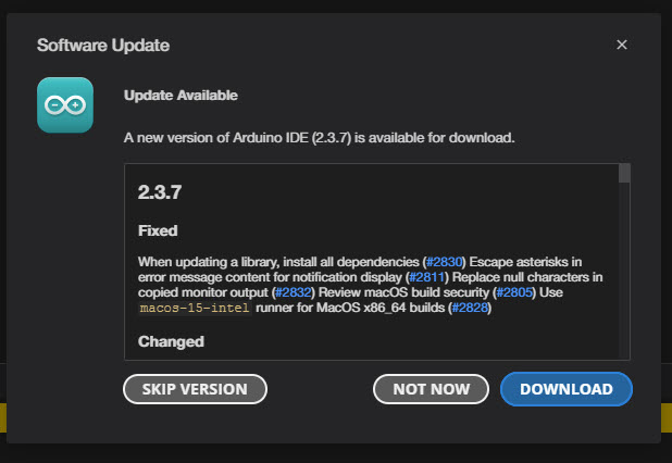
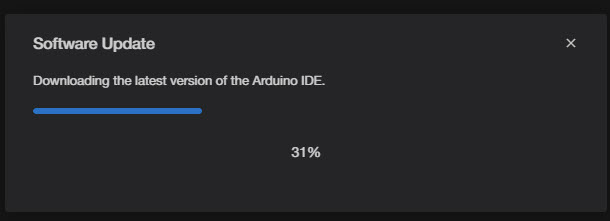
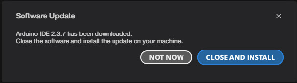
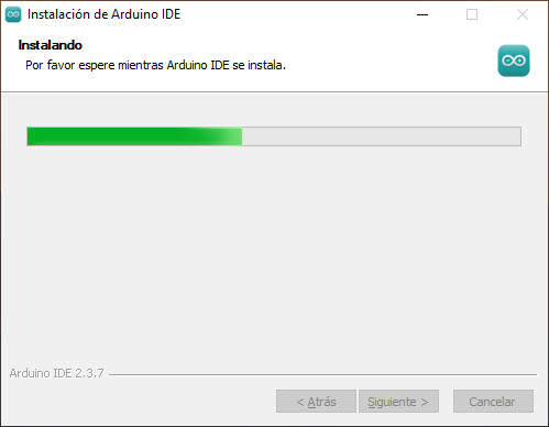
Let’s start with an Arduino IDE’s update:
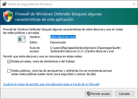
After a successful installation the IDE asks for some privileges to deal with the firewall.
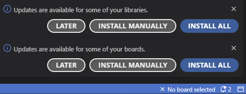
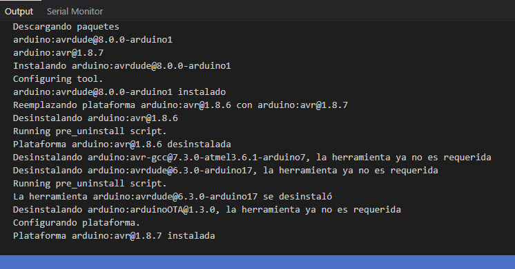
Let’s move on with the update of the libraries and the boards. In the Output tab we can see the progress of the libraries and boards update.
All set. Let’s start reading Quentin’s website.
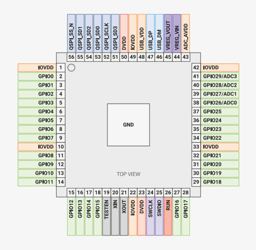
We will be working with the Seeed XIAO RP2040 board.
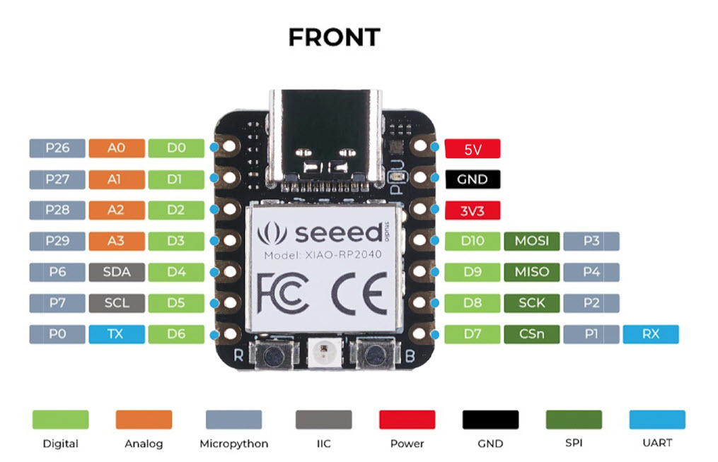
This is the pin map from Seeed’s website.
| XIAO Pin | Function | Chip Pin | Description |
|---|---|---|---|
| 5V | VBUS | Power Input/Output | |
| GND | |||
| 3V3 | 3V3_OUT | Power Output | |
| D0 | Analog | P26 | GPIO, ADC |
| D1 | Analog | P27 | GPIO, ADC |
| D2 | Analog | P28 | GPIO, ADC |
| D3 | Analog | P29 | GPIO, ADC |
| D4 | SDA | P6 | GPIO, I2C Data |
| D5 | SCL | P7 | GPIO, I2C Clock |
| D6 | TX | P0 | GPIO, UART Transmit |
| D7 | RX,CSn | P1 | GPIO, UART Receive,CSn |
| D8 | SCK | P2 | GPIO, SPI Clock |
| D9 | MISO | P4 | GPIO, SPI Data |
| D10 | MOSI | P3 | GPIO, SPI Data |
| Reset | RUN | RUN | |
| Boot | RP2040_BOOT | Enter Boot Mode | |
| CHARGE_LED | VCC_3V3 | CHG-LED_Red | |
| RGB LED | NEOPIX | RGB LED | |
| USER_LED_R | IO17_RGB-R | User-controlled red RGB LED pin | |
| USER_LED_B | IO25_RGB-B | User-controlled blue RGB LED pin | |
| USER_LED_G | IO16_RGB-G | User-controlled green RGB LED pin |
As explained in his GitLab’s site, in order to work with Arduino’s IDE, we should check the info in this GitHub’s repo, regarding Raspberry Pi Pico Arduino core, for all RP2040 and RP2350 boards.
We need to open up the Arduino IDE and go to File->Preferences.
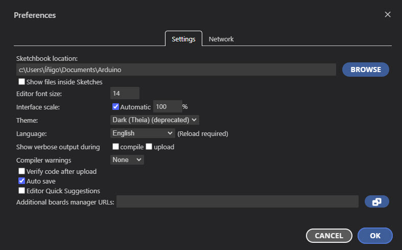
In the dialog that pops up, I entered the following URL in the “Additional Boards Manager URLs” field:
https://github.com/earlephilhower/arduino-pico/releases/download/global/package_rp2040_index.json
Down in the IDE a small window popped-up showing a progress bar with the installation of the JSON file.
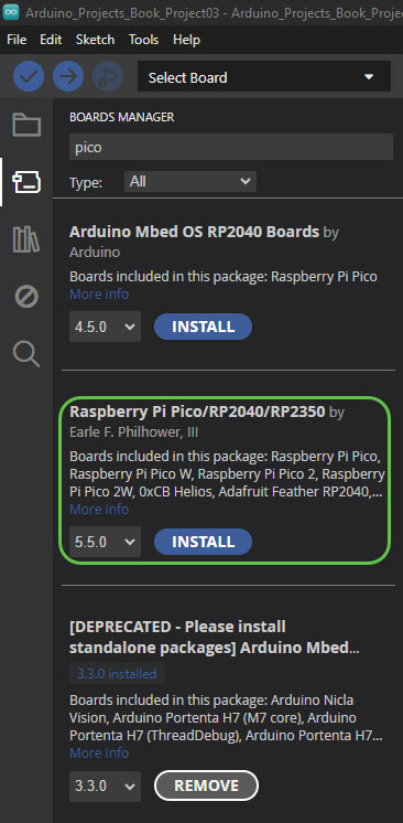
Then I went to Tools->Boards->Board Manager in the IDE and typed “pico” in the search box and hit on “Install”:
Once again the small window in the right-down corner popped up showing the progres of the installation:
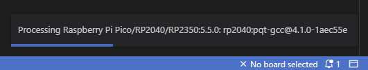
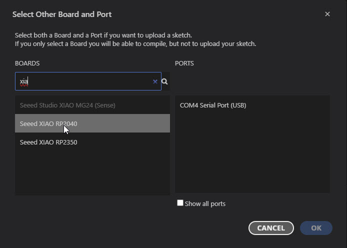
In the Boards field I looked for Xiao and selected the RP2040.
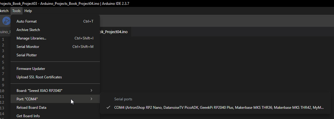
Afterwards I still see a message telling that there is no board connected. In “Tools > Port” I selected the right port.
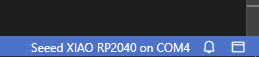
Now I see that the message in the lower right corner has changed:
In Quentin’s repo we can find several sketches for Arduino. As a common practice I went for the blinking led one. Once pasted or opened in my IDE, I click on Verify and, while compiling, I get an error:
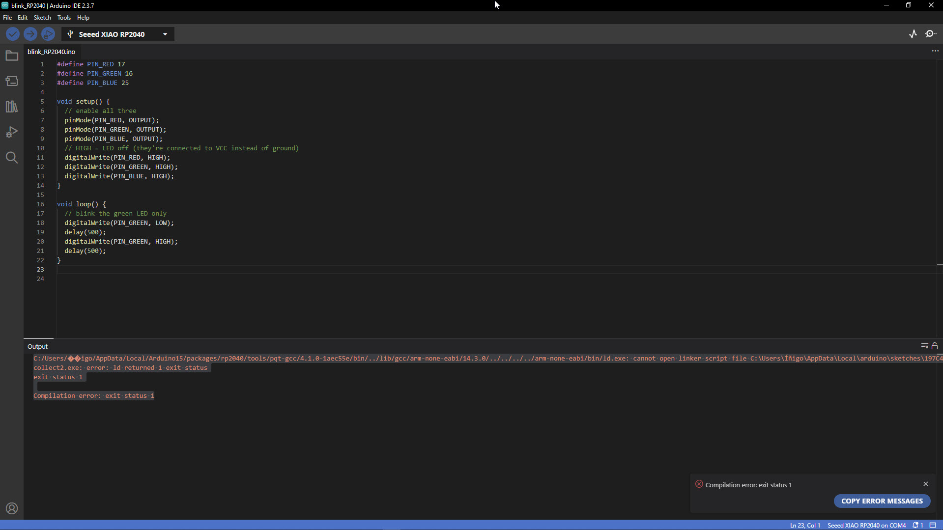
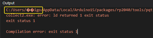
Basically there are some issues with my user name: Íñigo. The system seems not to like the “Í” and the “ñ”.
I shared my concerns with Claude, because last year I compiled several sketches for my Arduino UNO board. This is what Claude answered me:
It's not an intentional change penalising non-English characters. The difference lies in the toolchain:
- Arduino UNO uses the AVR-GCC toolchain, which has been around for decades and handles Windows paths with special characters well.
- XIAO RP2040 uses the ARM GCC (pqt-gcc) toolchain, maintained by a different team (Earle Philhower's RP2040 Arduino core). This toolchain is newer and does not handle non-ASCII characters in Windows paths properly.
C:\Users\John, not C:\Users\Íñigo. A typical case of linguistic bias in software development.
Workaround: Create a separate Windows user with an ASCII-only name (e.g.,
Inigo instead of Íñigo) and use that profile for compiling and uploading sketches targeting RP2040-based boards.
Before giving up, I tried a few things: moving the sketchbook to C:\Arduino, editing arduino-cli.yaml, creating symlinks with mklink… Nothing worked, because Arduino IDE 2.x uses some internal paths based on the Windows user profile and you can’t really change them. So I accepted my defeat and created a new Windows user (Inigo) with no special characters.
But this wasn’t the only problem with non-ASCII characters during the week. When testing an SSD1306 OLED display, I wanted to print ¡Hola fab academy world! using the Adafruit_GFX library. The ¡ character (inverted exclamation mark, very common in Spanish) just wouldn’t show up. Not with the default font, not with the extended Free* fonts either — they just ignored it.
On top of that, when I tried PlatformIO as an alternative IDE for the XIAO RP2040, the board was not in the official list. You can make it work through community forks like maxgerhardt’s platform-raspberrypi, but you have to manually edit platformio.ini to point to an external GitHub repo. Not ideal, especially for students who are just getting started.
giving back: GitHub contributions.
These three issues have something in common: the tools don’t always work well for non-English users. Instead of just finding workarounds and moving on, I decided to report them:
- Adafruit GFX Library — I opened a feature request asking for Latin-1 character support in the
Free*fonts. The original TTF files already have these characters, but they get lost during the font conversion. - Earle Philhower’s arduino-pico — I left a comment on issue #2689 with my experience, and suggested adding a warning about non-ASCII usernames in the installation docs.
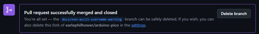
Update: Earle Philhower himself replied and invited me to submit a Pull Request to the docs. So I did — PR #3381. It was my first PR ever! The PR was merged and the warning is now part of the official documentation. 🥳
Below I describe the steps I followed to create it. - PlatformIO — I commented on feature request #68 asking for official XIAO RP2040 support, since this board is used a lot in Fab Academy and other educational programs.
How to create a Pull Request (PR) on GitHub using the web interface
- Fork the repository. I go to the original repo and click the Fork button (top right). This creates a copy under my own GitHub account.
- Navigate to the file I want to edit. In my fork, I browse to the file and click the pencil icon (✏️) to open the web editor.
- Make my changes. I edit the file directly in the browser. I can use Ctrl+F to find the exact spot where I need to add or modify content.
- Propose changes. I scroll down and fill in the commit details:
- A short, descriptive commit message (e.g.,
docs: add warning for non-ASCII Windows usernames). - An extended description with context if needed.
- I select “Create a new branch for this commit and start a pull request”.
- I give the branch a meaningful name (e.g.,
docs/non-ascii-username-warning). - Click Propose changes.
- A short, descriptive commit message (e.g.,
- Open the Pull Request. GitHub takes me to the PR creation page. I add a title and a description explaining what I changed and why. I reference any related issues (e.g.,
Ref #2689). Click Create pull request. - Wait for review. The repository maintainer will review my PR. Automated checks (CI builds) may run in the background. If the maintainer requests changes, I can edit the file directly from the PR page without starting over.
sketches
Once the creation of a new user is solved, I tried the different sketches from Quentin’s repo. One counterintuitive aspect with this board is that HIGH means LED off because they are connected to Vcc instead of ground (active-low configuration).
tab: blinking the green LED | Blink_Green.ino
#define PIN_RED 17
#define PIN_GREEN 16
#define PIN_BLUE 25

void setup() {
// enable all three
pinMode(PIN_RED, OUTPUT);
pinMode(PIN_GREEN, OUTPUT);
pinMode(PIN_BLUE, OUTPUT);

// HIGH = LED off (they're connected to VCC instead of ground)
digitalWrite(PIN_RED, HIGH);
digitalWrite(PIN_GREEN, HIGH);
digitalWrite(PIN_BLUE, HIGH);
}

void loop() {
// blink the green LED only
digitalWrite(PIN_GREEN, LOW);
delay(500);

digitalWrite(PIN_GREEN, HIGH);
delay(500);
}
tab: blinking all LEDs | Blink_RGB.ino
#define PIN_RED 17
#define PIN_GREEN 16
#define PIN_BLUE 25

void setup() {
  pinMode(PIN_RED, OUTPUT);
  pinMode(PIN_GREEN, OUTPUT);
  pinMode(PIN_BLUE, OUTPUT);
}

void loop() {
  // cycle through colors
  digitalWrite(PIN_RED, LOW);
  delay(500);
  digitalWrite(PIN_RED, HIGH);
  digitalWrite(PIN_GREEN, LOW);
  delay(500);
  digitalWrite(PIN_GREEN, HIGH);
  digitalWrite(PIN_BLUE, LOW);
  delay(500);
  digitalWrite(PIN_BLUE, HIGH);
}
tab: LED fading | Fade.ino
#define PIN_GREEN 16

void setup() {
  pinMode(PIN_GREEN, OUTPUT);
}

void loop() {
  for (int i = 0; i < 256; i++) {
    analogWrite(PIN_GREEN, i);
    delay(5);
  }
}
In this case, I adapted one of the classic Arduino example sketches (inside Arduino IDE go to File > Examples > 01.Basics > Fade). It’s a good way to get familiar with loops in C/C++.
tab: testing the display | test_display_RP2040.ino
#include <Wire.h>
#include <Adafruit_GFX.h>
#include <Adafruit_SSD1306.h>
#define SCREEN_WIDTH 128 // OLED display width, in pixels
#define SCREEN_HEIGHT 64 // OLED display height, in pixels
#define SCREEN_ADDRESS 0x3C // 0x3D or 0x3C depending on brand
Adafruit_SSD1306 display(SCREEN_WIDTH, SCREEN_HEIGHT, &Wire, -1, 1700000UL, 1700000UL);
void setup() {
// initialize Serial port
Serial.begin(115200);
// give the screen some time to power up
delay(50);
// initialize display
display.begin(SSD1306_SWITCHCAPVCC, SCREEN_ADDRESS);
display.clearDisplay();
display.display();
// text settings
display.setTextSize(1);
display.setTextColor(SSD1306_WHITE);
}
void loop() {
// clear the buffer
display.clearDisplay();
// pick a position
display.setCursor(28, 25);
// write to buffer
display.print("Hello world!");
// send buffer
display.display();
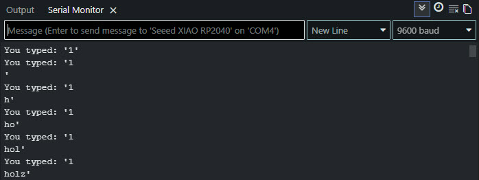
}tab: testing Serial communication | Serial.ino
#define BUFFER_SIZE 32

int count = 0;
char buffer[BUFFER_SIZE];

void setup() {
  Serial.begin(0);
}

void loop() {
  char c;

   if (Serial.available()) {
    c = Serial.read();
    buffer[count] = c;
    count++;
    buffer[count] = 0;
	    if (count == (BUFFER_SIZE-1)) {
	        count = 0;
		    }
	    Serial.print("You typed: '");
	    Serial.print(buffer);
	    Serial.println("'");
  }
}
And these are some examples of the output in the serial monitor:
tab: testing touch | test_touch_RP2040.ino
#define PIN_RED 17
#define PIN_GREEN 16
#define PIN_BLUE 25

#define N_TOUCH 6
#define THRESHOLD 6

int touch_pins[N_TOUCH] = {3, 4, 2, 27, 1, 26};
int touch_values[N_TOUCH] = {0, 0, 0, 0, 0, 0};

bool pin_touched_now[N_TOUCH] = {false, false, false, false, false, false};
bool pin_touched_past[N_TOUCH] = {false, false, false, false, false, false};

void update_touch() {
  int t;
  int t_max = 200;
  int p;

  for (int i = 0; i < N_TOUCH; i++) {
    p = touch_pins[i];

    // set to low
    pinMode(p, OUTPUT);
    digitalWriteFast(p, LOW);

    // settle
    delayMicroseconds(25);

    // enable pull-up
    pinMode(p, INPUT_PULLUP);

    // measure time to rise
    t = 0;
    while (!digitalReadFast(p) && t < t_max) {
      t++;
    }
    touch_values[i] = t;

    // update state
    pin_touched_past[i] = pin_touched_now[i];
    pin_touched_now[i] = touch_values[i] > THRESHOLD;
  }
}

void print_touch() {
  char print_buffer[30];
  for (int i=0; i < N_TOUCH; i++) {
    sprintf(print_buffer, "%4d ", touch_values[i]);
    Serial.print(print_buffer);
  }
  Serial.println("");
}

void setup() {
  // initialize Serial port
  Serial.begin(0);

  // initialize LED
  pinMode(PIN_RED, OUTPUT);
  pinMode(PIN_GREEN, OUTPUT);
  pinMode(PIN_BLUE, OUTPUT);
  // HIGH = LED off (they're connected to VCC instead of ground)
  digitalWrite(PIN_RED, HIGH);
  digitalWrite(PIN_GREEN, HIGH);
  digitalWrite(PIN_BLUE, HIGH);
}

void loop() {
  // update the touch sensors
  update_touch();

  // example pressed button
  if (pin_touched_now[0] && !pin_touched_past[0]) {
    // button 0 was just pressed, do something
    digitalWrite(PIN_GREEN, LOW);
  }

  // example released button
  if (!pin_touched_now[0] && pin_touched_past[0]) {
    // button 0 was just released, do something
    digitalWrite(PIN_GREEN, HIGH);
  }

  // print values to Serial, for debugging
  print_touch();

  // slow down the loop to not print too fast (optional)
  delay(50);
}
This sketch implements capacitive touch sensing by measuring the charge time of each pin. When a finger touches the pad, it adds capacitance, which increases the charge time. The values shown in the serial monitor reflect this: higher values mean more contact area (i.e., pressing harder). The THRESHOLD constant defines the minimum value to consider a pin as “touched”.
tab: end
2nd assignment.
For the second assignment, write and test a program for an embedded system using a microcontroller to interact (with input &/or output devices) and communicate (with wired or wireless connections), I went for a using the capacitive touch pads and the OLED display.
My sketch combines the capacitive touch reading with the OLED display, showing which pad is being touched. I went through several iterations to get it working properly.
tab: v1.0 — blank screen | pad_touch_v1.0.ino
In my first attempt, I wrote the touch detection logic and the display messages, but nothing appeared on the screen. After ruling out a hardware problem by loading a known-working display sketch, I reviewed the code and found that I was missing three essential display function calls in the loop():
display.clearDisplay()— without this, new content is drawn on top of old content.display.setCursor(0, 0)— without this, the text cursor position is undefined after clearing.display.display()— this was the critical one. Without it, the internal buffer is never sent to the physical screen, so nothing is visible.
I was also missing the print_touch() call, which meant I had no way to inspect the raw sensor values in the Serial Monitor for debugging.
#include <Wire.h>
#include <Adafruit_GFX.h>
#include <Adafruit_SSD1306.h>

#define SCREEN_WIDTH 128
#define SCREEN_HEIGHT 64
#define SCREEN_ADDRESS 0x3C

Adafruit_SSD1306 display(SCREEN_WIDTH, SCREEN_HEIGHT, &Wire, -1, 1700000UL, 1700000UL);

#define N_TOUCH 6
#define THRESHOLD 6

int touch_pins[N_TOUCH] = {3, 4, 2, 27, 1, 26};
int touch_values[N_TOUCH] = {0, 0, 0, 0, 0, 0};

int last_pad = -1;

bool pin_touched_now[N_TOUCH] = {false, false, false, false, false, false};
bool pin_touched_past[N_TOUCH] = {false, false, false, false, false, false};

void update_touch() {
  int t;
  int t_max = 200;
  int p;

  for (int i = 0; i < N_TOUCH; i++) {
    p = touch_pins[i];
    pinMode(p, OUTPUT);
    digitalWriteFast(p, LOW);
    delayMicroseconds(25);
    pinMode(p, INPUT_PULLUP);
    t = 0;
    while (!digitalReadFast(p) && t < t_max) {
      t++;
    }
    touch_values[i] = t;
    pin_touched_past[i] = pin_touched_now[i];
    pin_touched_now[i] = touch_values[i] > THRESHOLD;
  }
}

void print_touch() {
  char print_buffer[30];
  for (int i = 0; i < N_TOUCH; i++) {
    sprintf(print_buffer, "%4d ", touch_values[i]);
    Serial.print(print_buffer);
  }
  Serial.println("");
}

void setup() {
  Serial.begin(115200);
  delay(50);
  display.begin(SSD1306_SWITCHCAPVCC, SCREEN_ADDRESS);
  display.clearDisplay();
  display.setCursor(0, 0);
  display.print("Starting...");
  display.display();
  delay(2000);
  display.setTextSize(2);
  display.setTextColor(SSD1306_WHITE);
}

void loop() {
  // BUG: missing display.clearDisplay()
  // BUG: missing display.setCursor(0, 0)

  update_touch();
  // BUG: missing print_touch() — no way to debug via Serial Monitor

  char message[30];

  for (int i = 0; i < N_TOUCH; i++) {
    if (pin_touched_now[i]) {
      last_pad = i;
    }
  }

  if (last_pad == -1) {
    display.print("No pad pressed");
  } else {
    sprintf(message, "Pad number %d pressed", last_pad);
    display.print(message);
  }

  // BUG: missing display.display() — buffer never sent to screen
  delay(500);
}
tab: v1.1 — false positive on pad 4 | pad_touch_v1.1.ino
After fixing the display calls and adding print_touch(), the screen was working — but it immediately showed “Pad number 4 pressed” on startup, without me touching anything.
Thanks to print_touch(), I could now inspect the raw values in the Serial Monitor. I discovered that pad 4 had a resting value of ~8, while the other pads sat at 0–4. Since the threshold was set to 6, pad 4 was permanently above it.
The root cause: each pad has a different baseline capacitance depending on trace length, routing, and proximity to other components. A fixed absolute threshold doesn’t account for these differences.
#include <Wire.h>
#include <Adafruit_GFX.h>
#include <Adafruit_SSD1306.h>

#define SCREEN_WIDTH 128
#define SCREEN_HEIGHT 64
#define SCREEN_ADDRESS 0x3C

Adafruit_SSD1306 display(SCREEN_WIDTH, SCREEN_HEIGHT, &Wire, -1, 1700000UL, 1700000UL);

#define N_TOUCH 6
#define THRESHOLD 6

int touch_pins[N_TOUCH] = {3, 4, 2, 27, 1, 26};
int touch_values[N_TOUCH] = {0, 0, 0, 0, 0, 0};

int last_pad = -1;

bool pin_touched_now[N_TOUCH] = {false, false, false, false, false, false};
bool pin_touched_past[N_TOUCH] = {false, false, false, false, false, false};

void update_touch() {
  int t;
  int t_max = 200;
  int p;

  for (int i = 0; i < N_TOUCH; i++) {
    p = touch_pins[i];
    pinMode(p, OUTPUT);
    digitalWriteFast(p, LOW);
    delayMicroseconds(25);
    pinMode(p, INPUT_PULLUP);
    t = 0;
    while (!digitalReadFast(p) && t < t_max) {
      t++;
    }
    touch_values[i] = t;
    pin_touched_past[i] = pin_touched_now[i];
    pin_touched_now[i] = touch_values[i] > THRESHOLD;  // BUG: absolute comparison
  }
}

void print_touch() {
  char print_buffer[30];
  for (int i = 0; i < N_TOUCH; i++) {
    sprintf(print_buffer, "%4d ", touch_values[i]);
    Serial.print(print_buffer);
  }
  Serial.println("");
}

void setup() {
  Serial.begin(115200);
  delay(50);
  display.begin(SSD1306_SWITCHCAPVCC, SCREEN_ADDRESS);
  display.clearDisplay();
  display.setCursor(0, 0);
  display.print("Starting...");
  display.display();
  delay(2000);
  display.setTextSize(2);
  display.setTextColor(SSD1306_WHITE);
}

void loop() {
  display.clearDisplay();
  display.setCursor(0, 0);

  update_touch();
  print_touch();

  char message[30];

  for (int i = 0; i < N_TOUCH; i++) {
    if (pin_touched_now[i]) {
      last_pad = i;
    }
  }

  if (last_pad == -1) {
    display.print("No pad pressed");
  } else {
    sprintf(message, "Pad number %d pressed", last_pad);
    display.print(message);
  }

  display.display();
  delay(500);
}
tab: v1.2 — baseline calibration | pad_touch_v1.2.ino
Instead of comparing against a fixed threshold, I went for calibrating each pad’s baseline at start-up and detect touches based on the delta from that baseline.
During setup(), the sketch reads all pads 10 times and stores the maximum resting value for each one. Then in update_touch(), the comparison becomes (touch_values[i] - base_values[i]) > THRESHOLD.
This way, pad 4’s resting value of 8 is subtracted out, and only a genuine touch (which adds ~20–50 to the reading) triggers a detection. The display now correctly shows “No pad pressed” on start-up.
#include <Wire.h>
#include <Adafruit_GFX.h>
#include <Adafruit_SSD1306.h>

#define SCREEN_WIDTH 128
#define SCREEN_HEIGHT 64
#define SCREEN_ADDRESS 0x3C

Adafruit_SSD1306 display(SCREEN_WIDTH, SCREEN_HEIGHT, &Wire, -1, 1700000UL, 1700000UL);

#define N_TOUCH 6
#define THRESHOLD 6

int touch_pins[N_TOUCH] = {3, 4, 2, 27, 1, 26};
int touch_values[N_TOUCH] = {0, 0, 0, 0, 0, 0};
int base_values[N_TOUCH] = {0, 0, 0, 0, 0, 0};

int last_pad = -1;

bool pin_touched_now[N_TOUCH] = {false, false, false, false, false, false};
bool pin_touched_past[N_TOUCH] = {false, false, false, false, false, false};

void update_touch() {
  int t;
  int t_max = 200;
  int p;

  for (int i = 0; i < N_TOUCH; i++) {
    p = touch_pins[i];
    pinMode(p, OUTPUT);
    digitalWriteFast(p, LOW);
    delayMicroseconds(25);
    pinMode(p, INPUT_PULLUP);
    t = 0;
    while (!digitalReadFast(p) && t < t_max) {
      t++;
    }
    touch_values[i] = t;
    pin_touched_past[i] = pin_touched_now[i];
    pin_touched_now[i] = (touch_values[i] - base_values[i]) > THRESHOLD;
  }
}

void print_touch() {
  char print_buffer[30];
  for (int i = 0; i < N_TOUCH; i++) {
    sprintf(print_buffer, "%4d ", touch_values[i]);
    Serial.print(print_buffer);
  }
  Serial.println("");
}

void setup() {
  Serial.begin(115200);
  delay(50);
  display.begin(SSD1306_SWITCHCAPVCC, SCREEN_ADDRESS);
  display.clearDisplay();
  display.setCursor(0, 0);
  display.print("Starting...");
  display.display();
  delay(2000);
  display.setTextSize(2);
  display.setTextColor(SSD1306_WHITE);

  // Baseline calibration: read 10 times, store max per pad
  for (int q = 0; q < 10; q++) {
    update_touch();
    for (int k = 0; k < N_TOUCH; k++) {
      if (touch_values[k] > base_values[k]) {
        base_values[k] = touch_values[k];
      }
    }
  }
}

void loop() {
  display.clearDisplay();
  display.setCursor(0, 0);

  update_touch();
  print_touch();

  char message[30];

  for (int i = 0; i < N_TOUCH; i++) {
    if (pin_touched_now[i]) {
      last_pad = i;
    }
  }

  if (last_pad == -1) {
    display.print("No pad pressed");
  } else {
    sprintf(message, "Pad number %d pressed", last_pad);
    display.print(message);
  }

  display.display();
  delay(500);
}
tab: end
So for the final version of the sketch, I have a couple of videos.
In the first one, I am touching the capacitive pads and seeing the response on the OLED display in real time.
And for the second one, we use the serial monitor output to show raw touch values as each pad is pressed.
group assignment.
For the group assignment we have requested to demonstrate and compare the toolchains and development workflows for available embedded architectures.
First of all, I needed to get a good idea of what a toolchain means. After some digging, I came up with a pretty fair idea. Basically, a toolchain is the complete set of software tools required to go from source code to a running program on a microcontroller.
→ Fab Lab León 2026 Group Page
It typically includes:
- Compiler — translates C/C++ into machine code for the target architecture (e.g.
arm-none-eabi-gcc,avr-gcc). - Linker — combines compiled object files and libraries into a single binary.
- Programmer/flasher — transfers the binary to the microcontroller’s flash memory (e.g.
avrdude,picotool,esptool). - Debugger (optional) — step-by-step execution, breakpoints, register inspection, typically via SWD or JTAG.
In our case, we worked with the Seeed XIAO RP2040 (ARM Cortex-M0+). Our toolchain:
- Arduino IDE as the development environment.
- arduino-pico core providing board support.
arm-none-eabi-gccas the compiler, flashing the binary via UF2 — the board mounts as a USB drive and we simply drag the compiled file onto it.
micropython
To compare toolchains on the same architecture, we also explored MicroPython on the XIAO RP2040.
The workflow changes significantly: there is no compilation step. Instead, you flash a MicroPython firmware (.uf2) once, and then write Python scripts that run directly on the board through a REPL or by saving them as main.py. The toolchain reduces to a text editor and a serial terminal — or a dedicated IDE like Thonny, which combines both.
This contrast highlights how the same hardware can support very different development workflows: a compiled, library-rich environment with Arduino/C++, versus an interpreted, interactive approach with MicroPython.
In order to test MicroPython, I followed this well documented tutorial. Following it along I had a couple of issues:
-
Entering BOOTSEL mode. To flash the MicroPython
.uf2firmware, the XIAO RP2040 needs to appear as a USB mass storage device (RPI-RP2). The procedure is to hold the BOOT button while pressing RESET (or reconnecting USB). In my case it did not work on the first attempts — the board would reconnect but not show up as a drive. It took a few tries with different timing before it entered BOOTSEL mode correctly. This is worth being patient with: if the OS plays the “device connected” sound but no drive appears, try again.
USB mass storage device (`RPI-RP2`).. -
Misleading serial output before flashing. Before actually installing MicroPython, I connected the board to Thonny and selected the RP2040 interpreter. The shell immediately started displaying rows of zeros, which looked like communication was working. In reality, MicroPython was not installed at all — what I was seeing was the serial output from the previous Arduino sketch (the capacitive pad readings). This was confusing because it seemed like the firmware was already there. Lesson learned: serial output alone does not confirm that MicroPython is running. Look for the
>>>REPL prompt instead. -
Saving files to the board while a script is running. After flashing MicroPython, I tried to save the
ws2812.pylibrary to the board via Thonny (File → Save as → Raspberry Pi Pico). The save dialog got stuck on “Saving…” for several minutes. The reason was that a script was still running on the board and occupying the connection. The fix was simple: press Ctrl+C in the shell to interrupt the running script, wait for the>>>prompt, and then save the file. Lesson learned: the board needs to be idle before you can write files to its filesystem.
Afterwards I tried a couple of Python scripts:
tab: RGB LED test | ws2812.py
from ws2812 import WS2812
import utime
import machine
power = machine.Pin(11,machine.Pin.OUT)
power.value(1)
BLACK = (0, 0, 0)
RED = (255, 0, 0)
YELLOW = (255, 150, 0)
GREEN = (0, 255, 0)
CYAN = (0, 255, 255)
BLUE = (0, 0, 255)
PURPLE = (180, 0, 255)
WHITE = (255, 255, 255)
COLORS = (BLACK, RED, YELLOW, GREEN, CYAN, BLUE, PURPLE, WHITE)

led = WS2812(12,1)#WS2812(pin_num,led_count)

while True:
    print("Beautiful color")
    for color in COLORS:
        led.pixels_fill(color)
        led.pixels_show()
        utime.sleep(0.2)
The RGB LED light converts and flashes the lights. And the output of the text “Beautiful Color” will as well be displayed in the Shell.
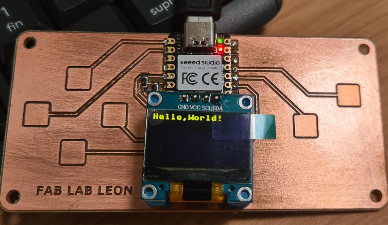
tab: OLED display test | ssd1306.py
from ssd1306 import SSD1306_I2C
from machine import Pin, I2C
from time import sleep

i2c = I2C(1, scl=Pin(7), sda=Pin(6), freq=200000)#Grove - OLED Display 0.96" (SSD1315)
oled = SSD1306_I2C(128, 64, i2c)

while True:
    oled.fill(0)#clear
    oled.text("Hello,World!",0,0)
    oled.show()
    #sleep(0.5)
Classical script to show a “Hello world!” message.
tab: end
reflection
This week was not my first contact with embedded programming — I studied industrial engineering and have also explored this area as a hobby over the years. But it had been a long time since I last worked at this level, and my C/C++ was quite rusty too. Having that background helped me move faster through the basics, but it also meant I could focus on aspects I had never explored before.
I have to say: I really enjoyed this week. Working with boards, sensors, displays, writing code that makes physical things respond — there is something deeply satisfying about it.
What surprised me the most was diving into the RP2040 datasheet and understanding the architecture behind the chip: the parallel design with independent memory banks, the bus crossbar, and especially the PIO — the idea of offloading time-critical tasks to dedicated state machines so the main cores stay free. This concept of deterministic execution and efficient task delegation was new to me and genuinely interesting.
I was also impressed by the capabilities of the XIAO RP2040 as a board. For its size and price, it packs a lot.
One thing I particularly enjoyed was getting comfortable reading and commenting on open-source libraries. Going through the code, understanding how it works, and daring to raise issues when something could be improved — that felt like a meaningful step.
And the highlight of the week: after reporting an issue on the arduino-pico core repository about Windows usernames with extended ASCII characters (like Íñigo), the maintainer responded positively and invited me to submit a pull request. I did (PR #3381), it got reviewed, validated and merged. It was one of those moments where you break through a barrier — contributing to an open-source project used by thousands of people. That felt really good.
Beyond the learning itself, what makes this week especially valuable is that everything I explored — the capacitive touch input, the OLED display, the communication between sensors and outputs — connects directly to my final project. This is not just an exercise: I am building skills and testing components that I will actually use. That combination of enjoying the process and knowing it has a real purpose ahead makes embedded programming a very rewarding part of this journey.