Computer-controlled cutting.
weekly schedule.
| Time block | Wed | Thu | Fri | Sat | Sun | Mon | Tue |
|---|---|---|---|---|---|---|---|
| Global class | 3 h | ||||||
| Local class | 2 h | 4 h | |||||
| Research | |||||||
| Design | 1 h | ||||||
| Fabrication | 1 h | 3 h | |||||
| Documentation | |||||||
| Review |
overview.
This week we get hands-on with two machines: the laser cutter and the vinyl cutter. The big task is designing a parametric press-fit construction kit — pieces that hold together without glue, just by friction. We also need to cut something on the vinyl cutter and, as a group, characterize the laser cutter in our lab.
One thing shaped how this week went: midway through it my main laptop (the Lenovo Legion 7) died with a BIOS fault and had to go to technical service. I finished the week on an older, much slower backup machine (a Lenovo Yoga S740 on Windows 10), rebuilding part of my toolchain from scratch. That cost me time and is the honest reason this assignment took longer than it should have. More on that in the reflections.
assignments.
- group assignment: lab safety training done, laser cutter characterized.
- individual: parametric press-fit kit designed from scratch in Fusion 360 and cut.
- individual: vinyl stickers cut.
- design files included.
- hero shots included.
group assignment.
safety training.
First things first — before touching any machine, I went through the safety training at Fab Lab León. The main rules for the laser cutter: never leave it running unattended, always check the ventilation is on, only use approved materials (absolutely no PVC or polycarbonate — they release toxic fumes), and keep the lid closed while cutting.
After the training I signed the safety form confirming I understood everything and was ready to use the machines.
link to group page.
The group assignment for Fab Lab León 2026 is here: → Fab Lab León 2026 Group Page.
laser cutter characterization.
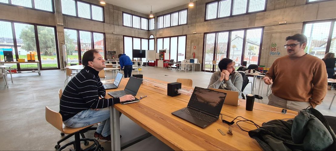
For the group assignment, we traveled from León to the Fab Lab in Ponferrada together with our local instructors. That’s where we did the hands-on characterization of the laser cutter, the press-fit comb test, and got familiar with the machine and its workflow.
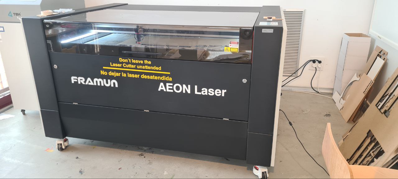
The laser cutter we used is a Framun Laser NOVA ELITE 14, a CO2 machine with 130 W of power and a pretty generous working area.
| Parameter | Value |
|---|---|
| Model | Framun Laser NOVA ELITE 14 |
| Laser type | CO2 (glass tube) |
| Power | 130 W |
| Working area | 1400 × 900 mm |
| Max cutting thickness | 0–30 mm (depends on material) |
| Focus distance | 7 mm |
| Software | RDWorks |
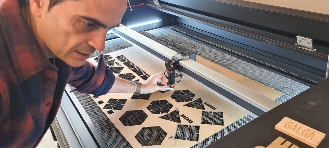
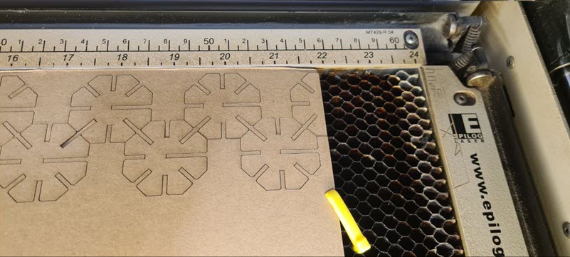
We ran the machine hands-on during the group session: setting focus, framing the job and cutting cardboard on the big bed.
ventilation.
Before every job we turned on the extraction and filtration system. The machine has air assist as well, which helps reduce flare-ups and keeps the cut cleaner. After finishing, we waited a few seconds before opening the lid to let the fumes evacuate.
software workflow.
This machine uses RDWorks instead of Rhinoceros. The workflow is a bit different from what I was used to seeing at León:
- Import or create the design in RDWorks.
- Assign layers by operation type — raster/scan for engraving, cut/vector for cutting. Important: always set engraving layers to process before cutting layers.
- Configure speed, power (min and max), and set Blow Select to LOW.
- Send the file to the machine via the Download button (file name max 8 characters).
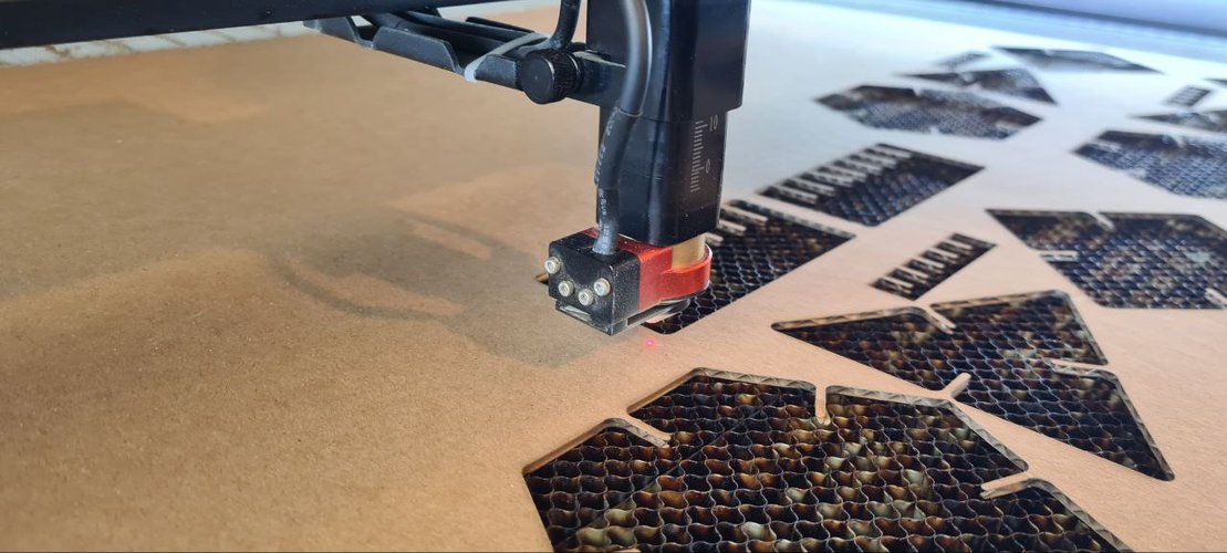
- On the machine: set origin, adjust focus using the 7 mm gauge, run FRAME to verify the job fits inside the material.
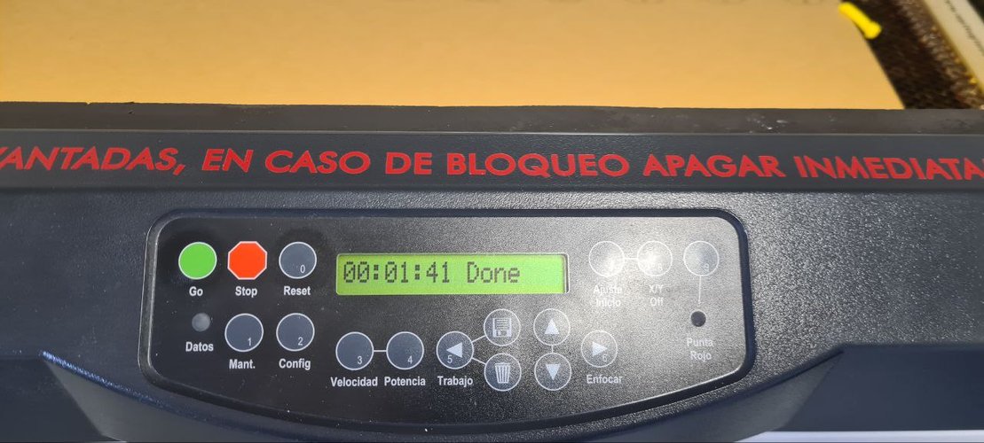
- Turn on extraction, close the lid, press START, and supervise the entire process.
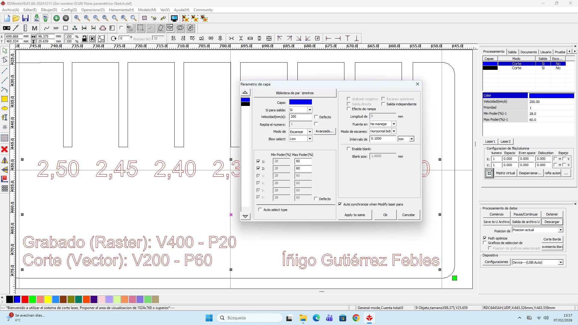
cutting parameters for corrugated cardboard (Framun).
These are the parameters I used for 2.3 mm corrugated cardboard on the Framun:
| Operation | Speed | Power |
|---|---|---|
| Cut (vector) | 200 | 60 |
| Engrave (raster) | 400 | 20 |
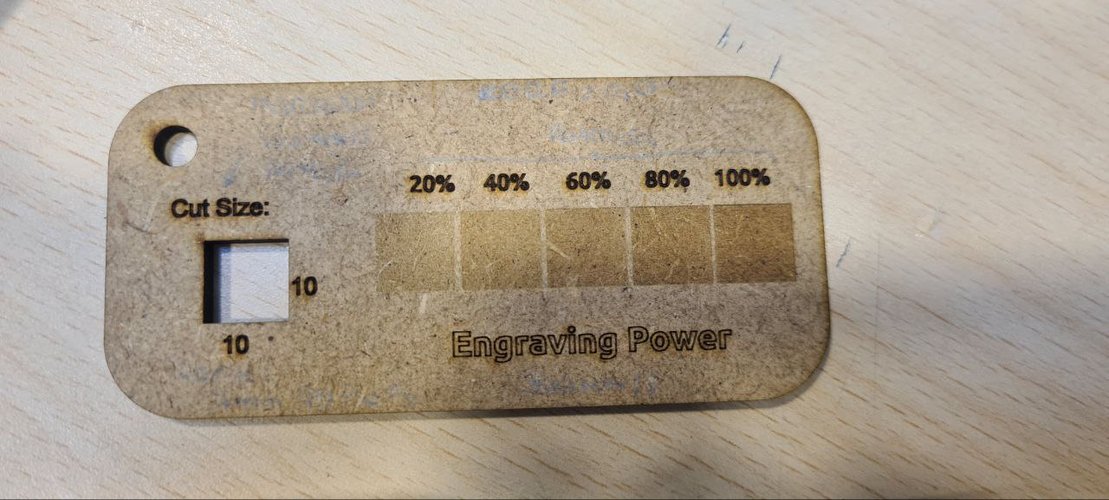
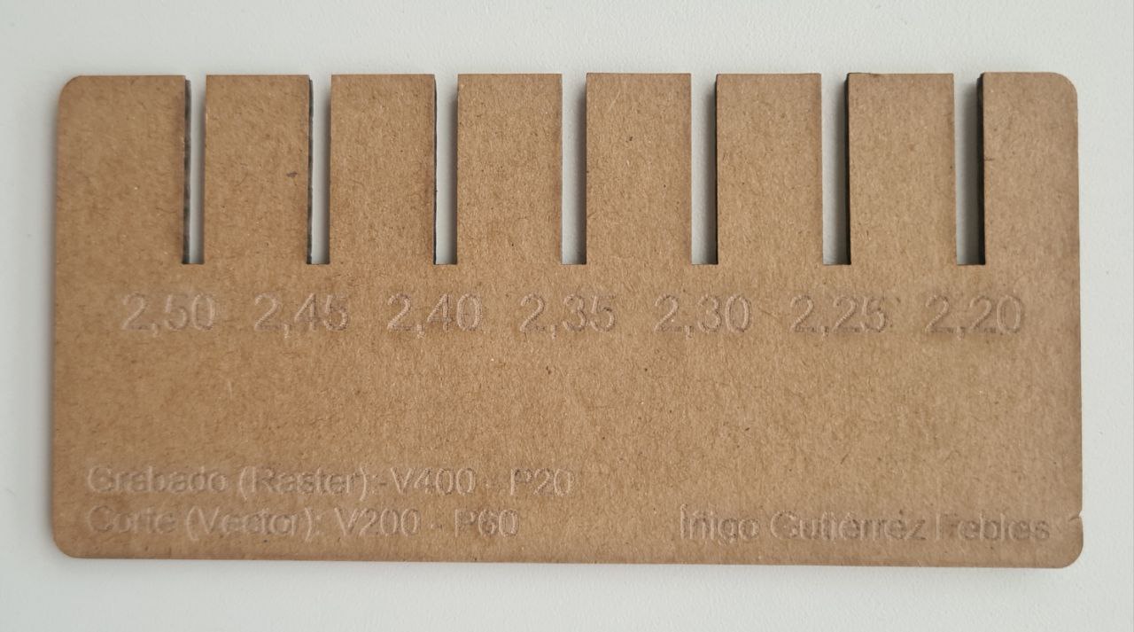
For the engraving side we also looked at a step gauge that burns the same area at 20, 40, 60, 80 and 100 % power, which makes it easy to pick an engraving power that’s visible without scorching the cardboard.
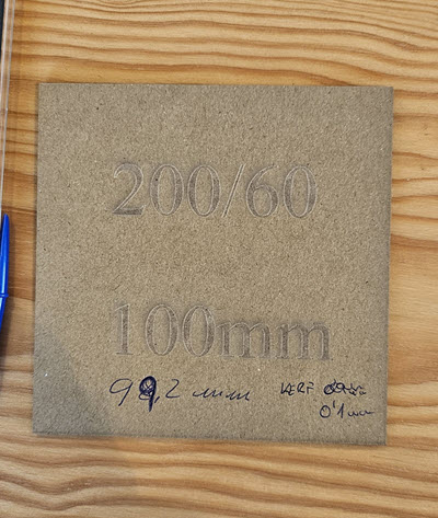
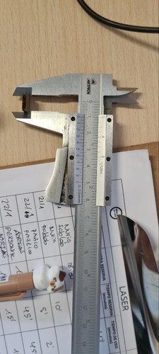
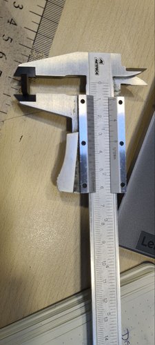
kerf and joint clearance.
To calculate the kerf, we designed a 100 × 100 mm square, cut it, and measured the result with a digital caliper. The measured piece came out at 99.8 mm instead of 100 mm.
Since the laser removes material on both sides of the cut line:
Kerf = (100 − 99.8) / 2 = 0.1 mm per side
We characterized the kerf in Ponferrada on the Framun and re-checked it back at Fab Lab León on the Epilog, getting consistent results, so I used 0.1 mm per side as the working value for the design.
For the joint clearance I used the press-fit comb (see the individual section): a single press-fit slot joint, where the slot width is the material thickness minus the kerf compensation. The sweet spot for 2.3 mm corrugated cardboard was 2.20 mm, which matches slot_width = thickness − kerf = 2.3 − 0.1.
This value can change depending on material type, thickness, focus accuracy and cutting parameters, so it’s always a good idea to re-test when switching materials or machines.
what I learned from the group work.
Going to Ponferrada was useful because I got to see a different machine and a different software workflow (RDWorks vs Rhinoceros + Epilog driver). The fundamentals are the same — layers, parameters, test cuts — but the interface and some details change. It also reinforced the idea that parameters are never universal: even with the same material, each machine has its own sweet spot. Always test before committing.
individual assignment — laser cutting.
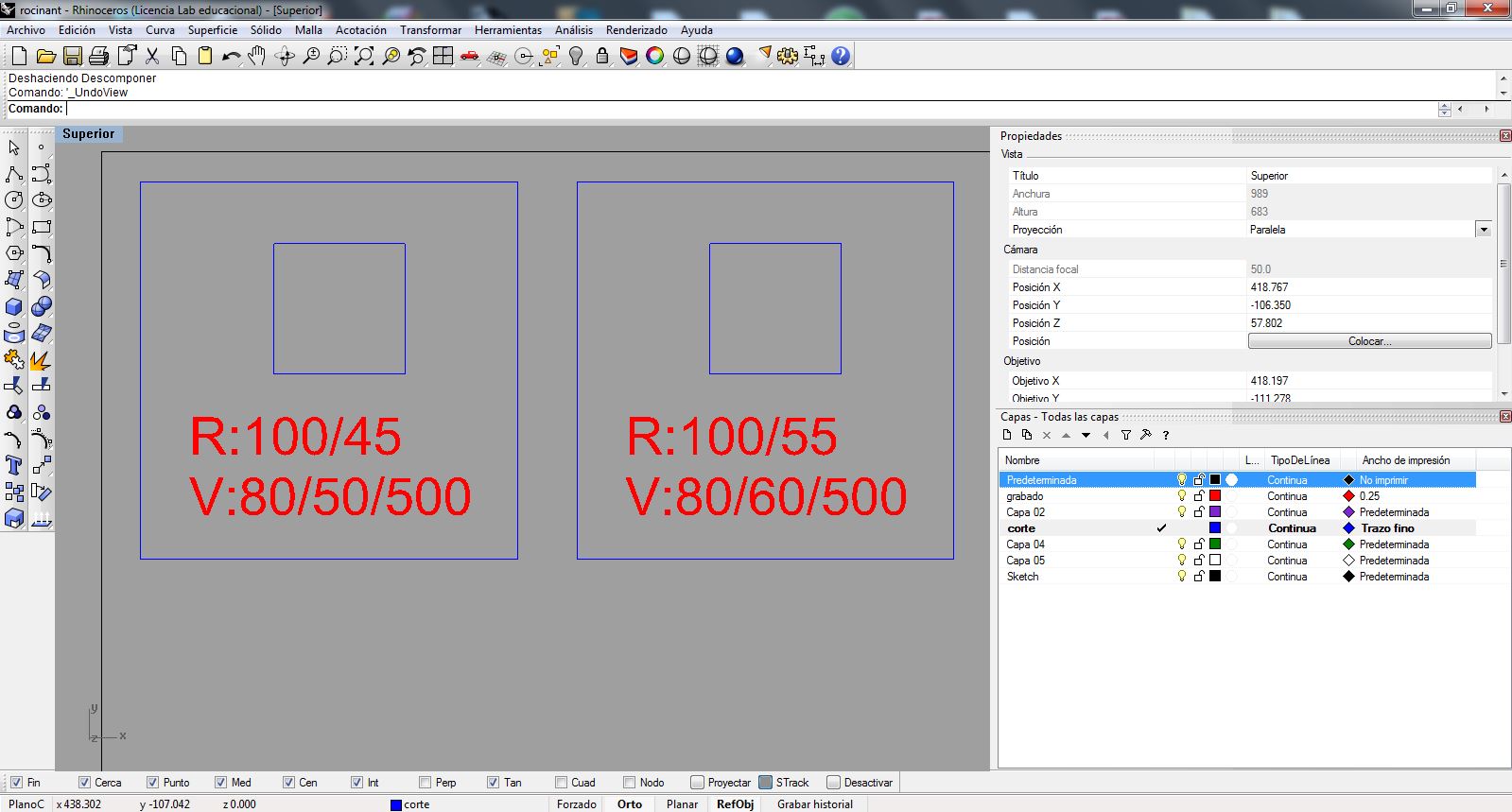
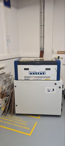
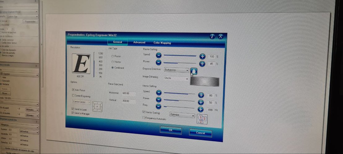
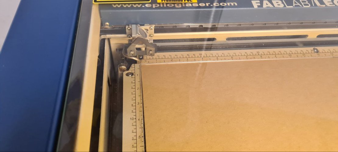
the machine at León (Epilog Mini 24).
The press-fit kit itself was cut back at Fab Lab León on the Epilog Mini 24, a 40 W CO2 machine driven from Rhinoceros through the Epilog print driver. This is a different machine from the Framun we characterized as a group, so its settings don’t carry over directly.
| Spec | Value |
|---|---|
| Model | Epilog Mini 24, CO2 |
| Power | 40 W |
| Working area | 610 × 305 mm |
| Driver | Rhinoceros + Epilog print driver |
| Layer system | color mapping (blue = cut) |
These are the settings I used for 2.3 mm corrugated cardboard, read straight from the Epilog driver:
| Operation | Speed | Power | Frequency |
|---|---|---|---|
| Cut (vector) | 80 % | 50 % | 499 Hz |
| Engrave (raster) | 100 % | 45 % | — |
press-fit test (the comb).
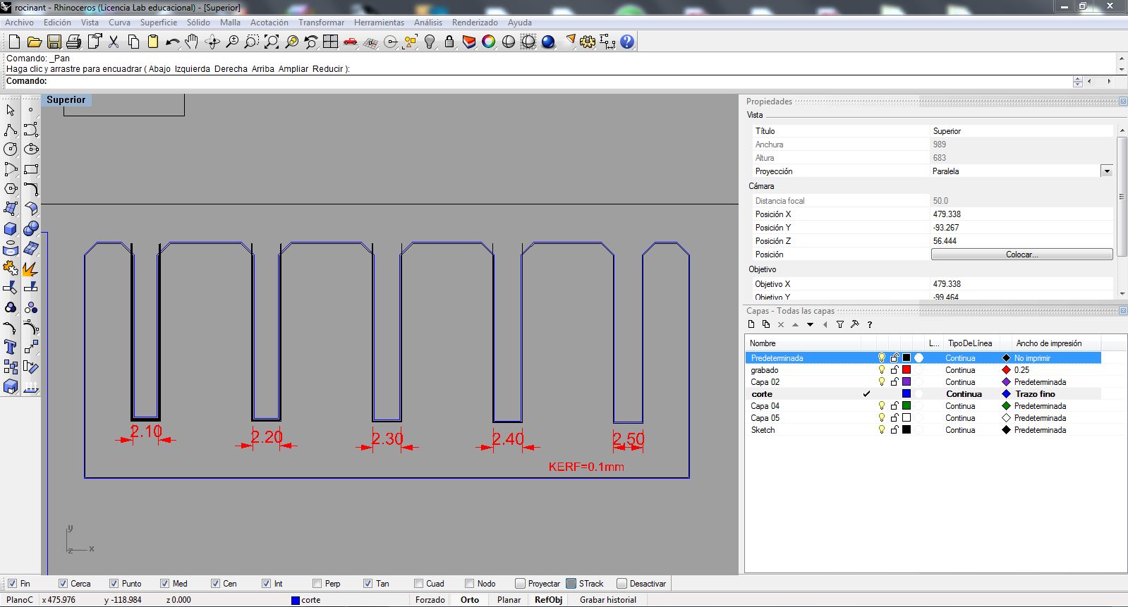
Before jumping into the final design, I needed to figure out the right slot width for a good press-fit in my material. I made a measurement comb — a piece with several slots in small steps, each one labeled directly on the part. The idea is simple: cut it, try fitting pieces into each slot, and see which one grabs best.
I iterated the comb a couple of times (first in Rhinoceros, then parametrically in Fusion) and cut a version on the Framun (V200 / P60) with slots in 0.05 mm steps from 2.20 to 2.50 mm, with the kerf baked in. After testing the fit, the sweet spot for my 2.3 mm cardboard was 2.20 mm — tight enough to hold, loose enough to assemble without forcing.
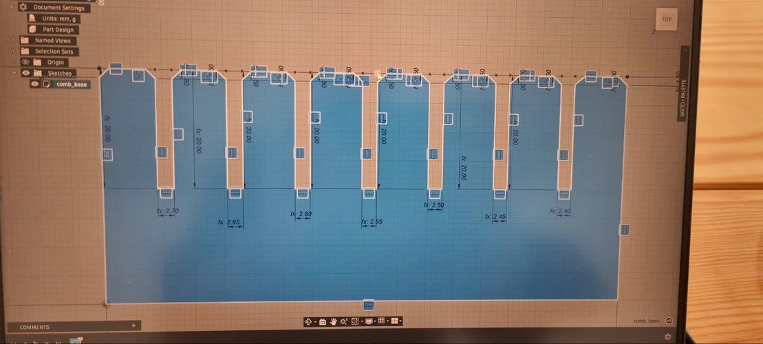
parametric design in Fusion 360.
I used Fusion 360 for the parametric design. The key idea behind parametric design is that you define dimensions as variables instead of fixed numbers. So if I change the material thickness from 2.3 to 3.0 mm, every slot in the design updates automatically.
user parameters.
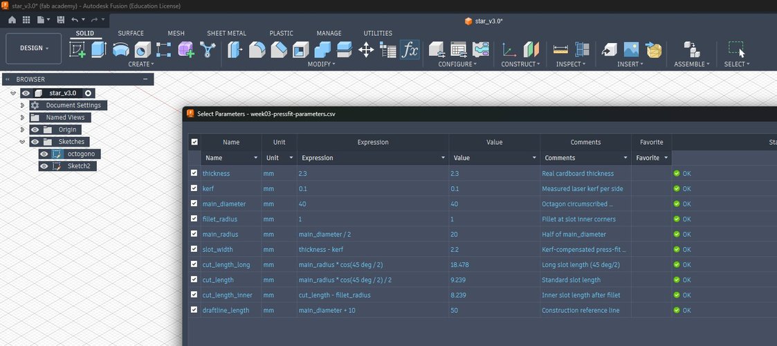
In Fusion I went to Modify → Change Parameters and created these variables. The base values (thickness, kerf, main_diameter, fillet_radius) drive everything else, and the press-fit slot is cut at slot_width, which is the material thickness minus the measured kerf:
| Name | Unit | Expression | Value |
|---|---|---|---|
| thickness | mm | 2.3 | 2.3 |
| kerf | mm | 0.1 | 0.1 |
| slot_width | mm | thickness - kerf | 2.2 |
| main_diameter | mm | 40 | 40 |
| main_radius | mm | main_diameter / 2 | 20 |
| fillet_radius | mm | 1 | 1 |
| cut_length_long | mm | main_radius * cos(45 deg / 2) | 18.48 |
| cut_length | mm | main_radius * cos(45 deg / 2) / 2 | 9.24 |
| cut_length_inner | mm | cut_length - fillet_radius | 8.24 |
| draftline_length | mm | main_diameter + 10 | 50 |
design concept.
I got the inspiration from Joanne Leong’s work in the MIT “How to Make (almost) Anything” course (Fall 2021). She used an octagon-based piece with slots at 90° and 45° to build a dragon — I loved the idea of starting from a simple polygon and getting organic shapes out of it.
The piece has seven identical slots around the perimeter and one deeper slot that serves as a differentiated connection point. This asymmetry lets you connect pieces in different orientations and build varied structures from a single piece type — the kit can be assembled in more than one way, not just into a single fixed shape. In my case, I went for a gondola instead of a dragon.
building it parametrically.
For the first physical cut I started from Joanne’s original FreeCAD file, adapting the slot-width parameter to match my material (2.3 mm cardboard, 0.1 mm kerf), exporting the DXF and cutting on the Epilog Mini 24 at León. That got me physical pieces, but it isn’t really my design — it’s someone else’s, with one value changed.
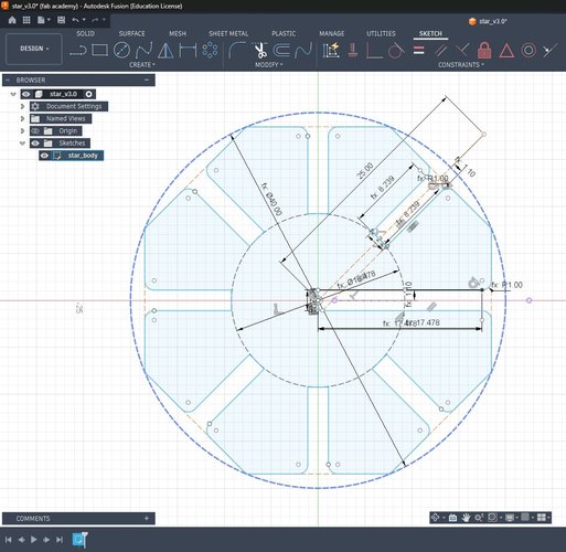
So I rebuilt the piece from scratch in Fusion 360 to actually own the parametric workflow. I imported the user parameters from a CSV (the table above), drew the octagon and one base slot constrained against slot_width (never a hard number), filleted the slot bottom with fillet_radius, and then used a Circular Pattern (Modify → Pattern → Circular, Distribution: Full, Quantity: 8) around the centre to lay out the repeating slots, keeping the differentiated deeper slot as the asymmetric connection point. The whole profile closes into a single fillable region, so it extrudes and exports cleanly.
The first rebuild (star-v3.0) closed and cut fine, but it wasn’t 100% constrained — a few segments stayed blue. I went back and locked every degree of freedom on the base sector: anchored the centre to the origin, fixed the octagon rotation with a perpendicular on one edge, tied each petal tip to the octagon vertex (so cut_length_long is no longer needed — the inscribed octagon already fixes it) and pinned the fillet corners before filleting. That produced the fully-constrained star-v3.1, which is the version the demonstration below runs on.
export to DXF and verification.
Fusion does not export DXF from the solid — you export the sketch. Before exporting I unchecked Construction Geometries in the Sketch Palette so the Ø40 and Ø18.478 reference circles wouldn’t be written into the file (construction geometry is excluded from the DXF anyway, but hiding it keeps the export obviously clean). I saved it as star-v3.0.dxf.
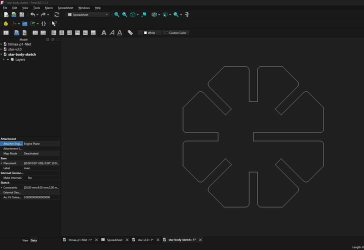
Since I don’t use Rhino on this machine, I verified the DXF in FreeCAD: I checked that the outer diameter measures 40 mm (no scale factor — Fusion sometimes drops a 2.3 mm slot to 0.23 mm) and that the file contains only the star outline, with no leftover construction circles or 45° lines that the laser would try to cut.
parametric demonstration.
The real test of a parametric model is whether you can change a driving value and have everything else follow without breaking. With the sketch fully constrained (no free degrees of freedom — nothing moves when you drag it), I opened Modify → Change Parameters and changed a single variable, thickness, from its real value of 2.3 mm up to 5 mm. Nothing else was touched.
slot_width = thickness − kerf recomputes from 2.2 to 4.9 mm, every one of the eight slots widens at once, and the whole star rebuilds with no errors and no deformation: the eight petals stay identical and symmetric, the circular pattern holds, and the part remains a single closed, extrudable region. That is the difference between a parametric model and a drawing — one number propagates through the entire part. I re-exported this fully-constrained version as star-v3.1.dxf / star-v3.1.f3d, the files linked at the bottom of the page.
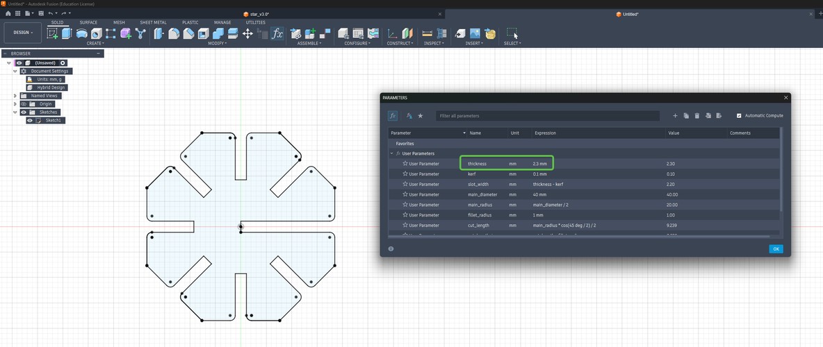
thickness = 2.3 mm → slot_width = 2.2 mm (the value I cut).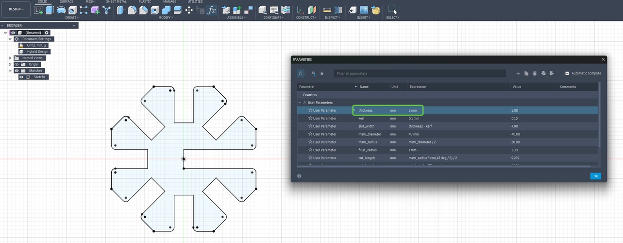
thickness changed to 5 mm → slot_width = 4.9 mm, and the whole star recomputes without deforming.cutting the pieces.
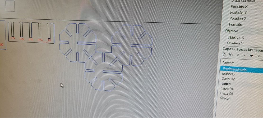
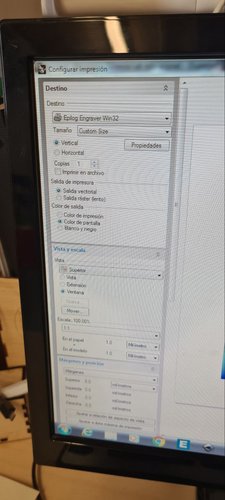
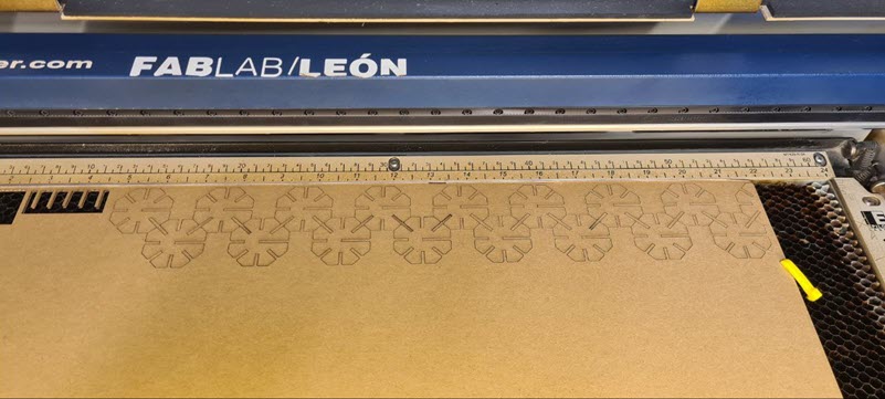
In Rhinoceros, I arranged multiple copies of the piece on the cardboard area to get as many as possible with minimal waste. Then I followed the standard León workflow: layers with the right colors (blue for cut), fine line widths, the cardboard parameters above, sent to the Epilog driver as vectorial output, origin set on the machine, ventilation on, and eyes on the machine the whole time.
the single piece.
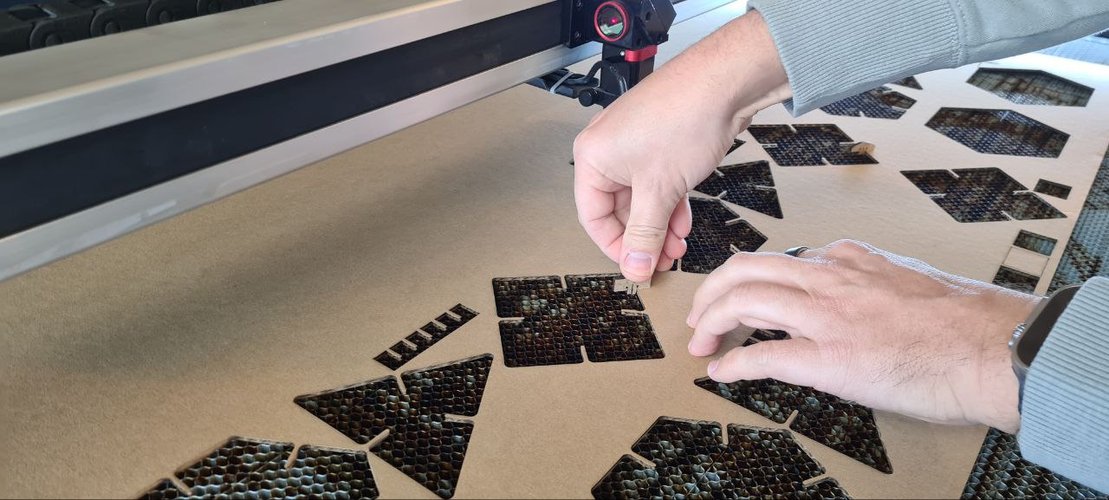
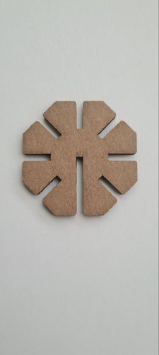
This is one module on its own: an octagon with seven identical slots and one deeper slot, cut in 2.3 mm cardboard. The whole kit is just many copies of this one part.
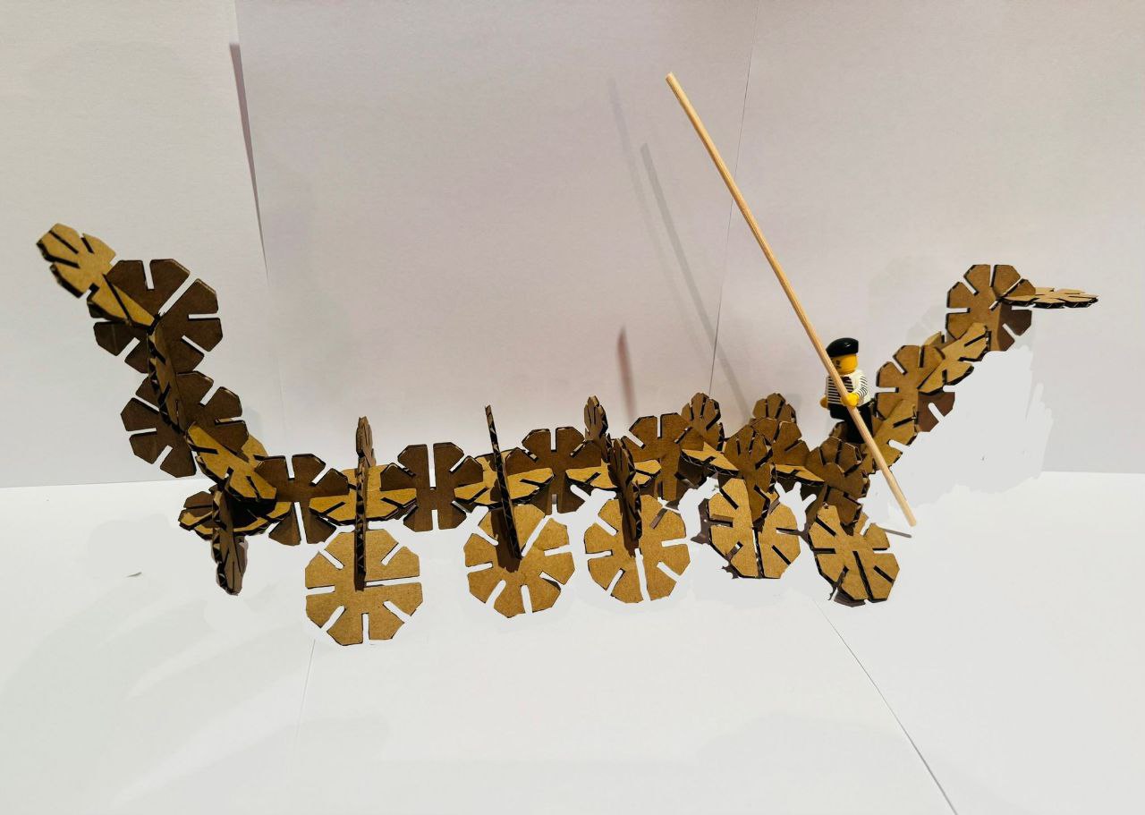
the gondola.
With all the pieces cut, I assembled them into a gondola. This was a fun way to show that the kit can produce complex 3D shapes from a single piece type.
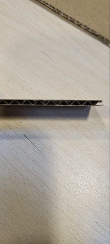
The press-fit joints hold firmly — you can pick up the whole structure and it stays together, no glue needed. The corrugated cardboard helps here: the internal wavy layer acts like a small spring inside the slot, which adds grip.
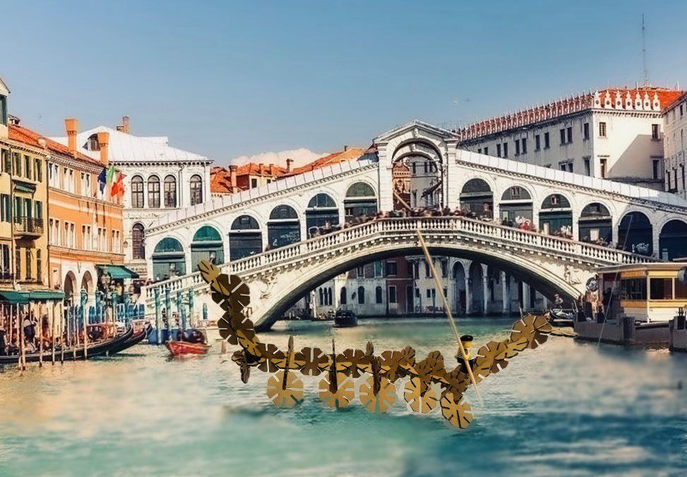
And because why not, I made a quick photomontage placing the gondola in Venice, floating next to the Rialto Bridge.
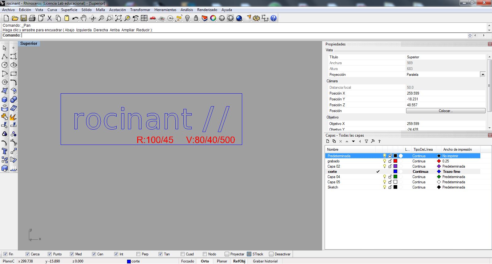
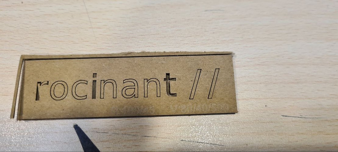
bonus — laser-cut logo.
While I was at it I also cut my own rocinant // logo in cardboard. I drew the wordmark in Illustrator, converted the text to outlines and exported it as a PDF (Acrobat 5 / PDF 1.4) so it would import cleanly into Rhino. In Rhino I put it on the cut and engrave layers (raster R:100/45, vector V:80/40/500) and ran it on the Epilog.
individual assignment — vinyl cutting.
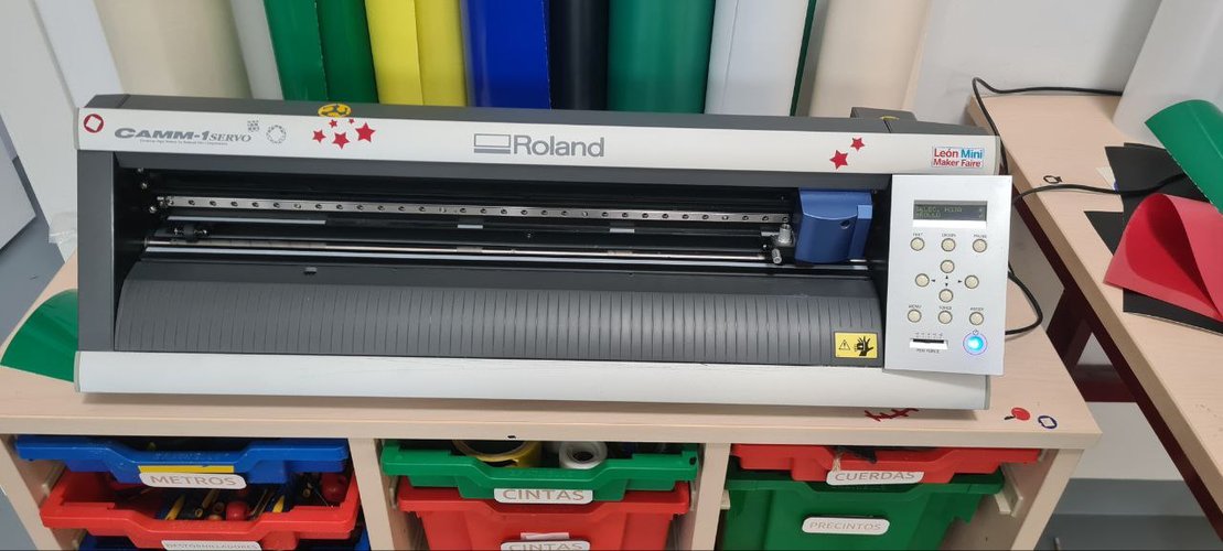
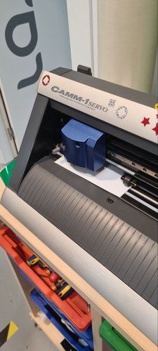
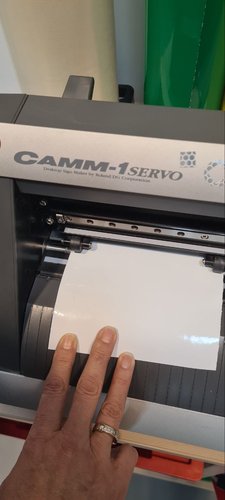
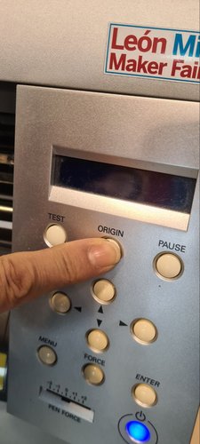
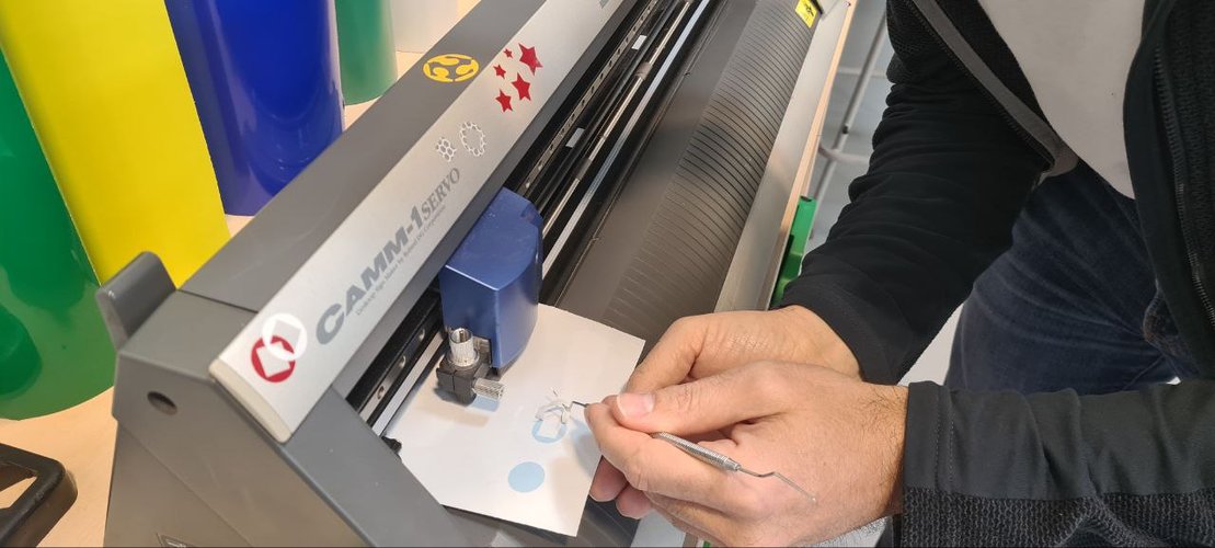
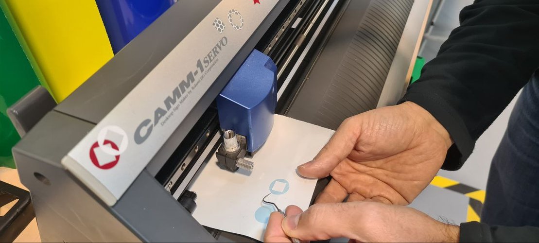
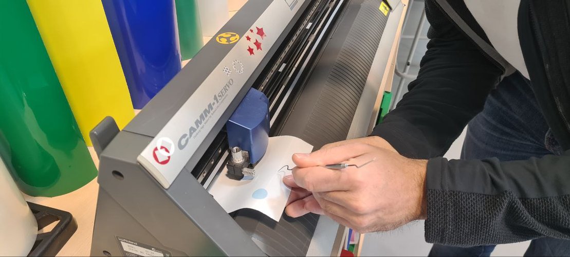
the machine.
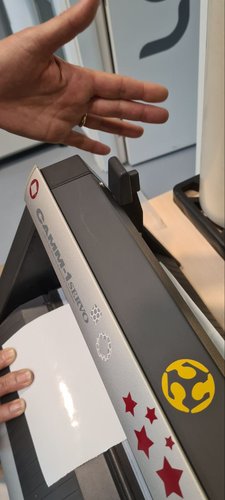
For vinyl cutting I used the Roland GX-24 at the lab. It’s a pretty straightforward machine — a small blade moves over the vinyl sheet and cuts along vector paths.
| Parameter | Value |
|---|---|
| Model | Roland GX-24 (CAMM-1 Servo) |
| Max cutting width | 584 mm |
| Max cutting speed | 500 mm/s |
| Blade angle | 45° |
| Software | Rhinoceros + Roland CutStudio driver |
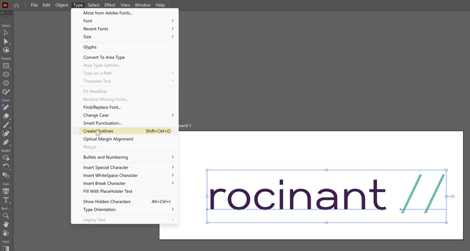
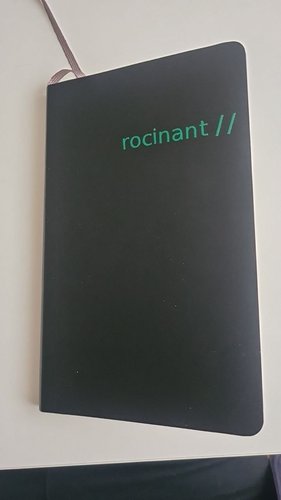
design.
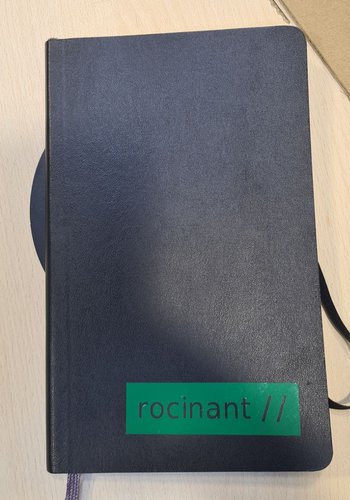
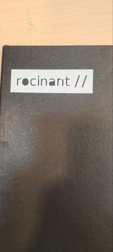
I wanted to make custom stickers for my notebook with my professional brand name: “rocinant //”. I made two versions — one in white vinyl and one in green vinyl — to see which one worked better on the dark cover.
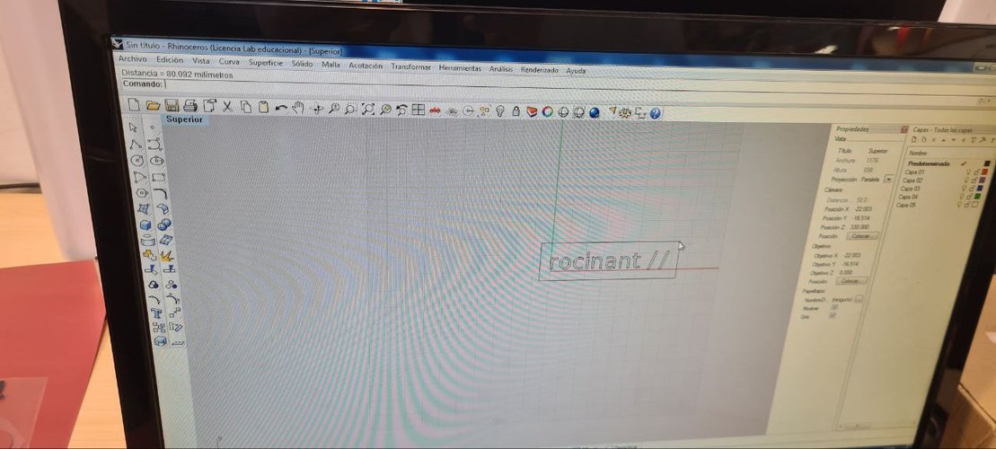
I drew the wordmark in Illustrator and converted the text to outlines (Type → Create Outlines), then brought it into Rhinoceros to send through the Roland driver. The wordmark is about 80 mm wide. Important: text has to be converted to outlines (a path) before cutting, otherwise the machine won’t know what to do with live text.
cutting process.
The workflow:
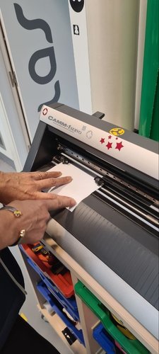
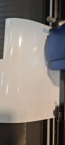
- Loaded the vinyl roll into the Roland, aligned it with the rollers.
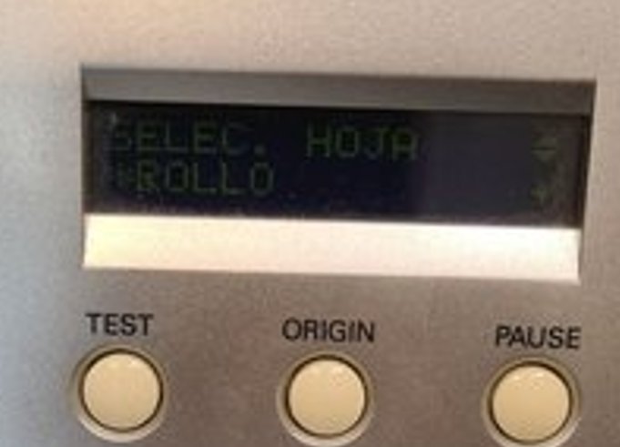
- Selected “Roll” mode on the machine display (SELEC. HOJA → ROLLO).
- Sent the design from Rhino through the Roland driver.
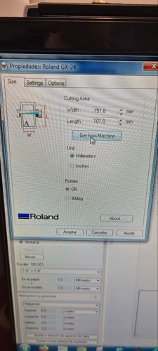
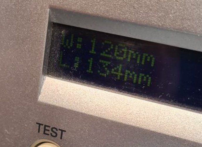
- Used “Get from machine” to check available material size.
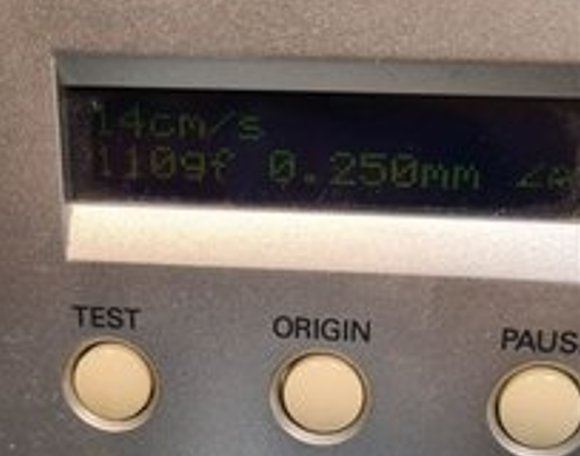
- Set the cutting parameters on the machine: speed 14 cm/s, force 110 gf, blade offset 0.25 mm.
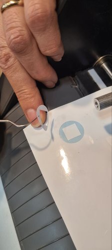
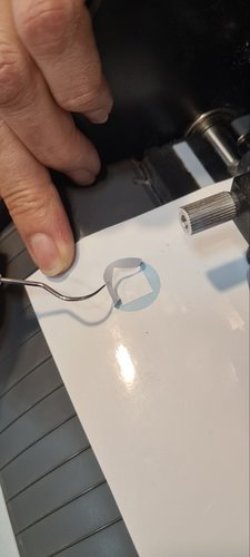
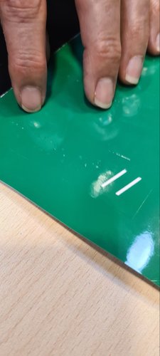
- Ran a quick test cut — small shapes, a circle and a square. If they peel off cleanly without cutting through the backing, the pressure is right.
- Set the origin and cut the final design.
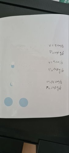
dialing in the parameters.
I didn’t just guess the speed. I cut the same shapes at three speeds — 5, 9 and 14 cm/s, keeping the force constant at 110 gf — and compared the edges and how cleanly each one weeded. The slower passes didn’t buy any quality on this thin adhesive vinyl, so I settled on 14 cm/s / 110 gf for the final cut.
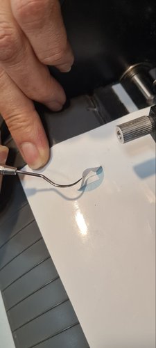
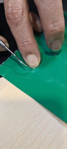
weeding and application.
After cutting, I removed the excess vinyl around the letters (this is called weeding). Then I applied transfer tape over the design, pressed it down, peeled the backing, and stuck it on the notebook. Straightforward process, but you need patience with small details — the letters can lift if you rush it. The test cut (the circle and square) gets weeded the same way to confirm the blade only cuts the vinyl, not the backing. I weeded both the white and the green runs.
result.
I ended up trying two treatments: plain outline letters and a knocked-out block with the text reversed out of a solid colour, applied to a couple of Moleskine covers. The white block reads with the most contrast, but the plain green letters on the black soft cover look the cleanest and match my brand colour, so that’s the one I’m keeping for daily use.
reflections.
This was my first real week working with fabrication machines, and the biggest lesson was how iterative the whole process is. You don’t just design and cut — you characterize, test, measure, adjust and test again. The parametric approach saved me a lot of time because once the variables were set up, adapting the design was just changing a number.
Building the gondola was probably the most satisfying part. It’s one thing to design a single piece on screen, but seeing dozens of them come together into a 3D structure that actually holds — that felt like proper digital fabrication. Having the chance to meet my fellow colleagues in person in Ponferrada, as well as Javi, the local instructor there, was great.
The honest low point was hardware, not fabrication. Halfway through the week my main laptop (Lenovo Legion 7) failed with a BIOS error and went to technical service. I had to fall back to a much older and slower machine (a Lenovo Yoga S740 on Windows 10) and rebuild part of my development environment on it. That ate into my design and documentation time and is the real reason this week’s delivery slipped. Lesson to remember: keep a working backup environment ready before you actually need it, not after the main machine dies.
A second lesson is about ownership of the design. Cutting from an adapted FreeCAD file gave me parts quickly, but it isn’t the same as building the parametric model myself — which is what the assignment is really about. Adapting someone else’s file is not the same as demonstrating your own parametric workflow, so I rebuilt the piece from scratch in Fusion 360 with my own user parameters and a circular pattern, and that Fusion model is the design I actually stand behind for this week.
design files.
- Press-fit piece — DXF (.dxf)
- Press-fit piece — Fusion 360 (.f3d)
- rocinant // wordmark, outlined — SVG (.svg) — vinyl cut design
- rocinant // wordmark, outlined — PDF (.pdf) — laser-cut logo
The first cut was adapted from Joanne Leong’s original FreeCAD file (see the note in the parametric design section).