Computer-aided design
weekly schedule
| Time block | Wed | Thu | Fri | Sat | Sun | Mon | Tue |
|---|---|---|---|---|---|---|---|
| Global class | 3 h | ||||||
| Local class | 1.5 h | 1.5 h | |||||
| Research | 1 h | 1 h | 2 h | 2 h | |||
| Design | 1 h | 4 h | 2 h | 5 h | |||
| Fabrication | |||||||
| Documentation | 5 h | 1 h | 2 h | 1 h | 3 h | ||
| Review | 1 h |
overview
Week 2 focuses on exploring 2D and 3D design tools to model a possible final project. The goal is to evaluate different software options, document the modelling process, and learn proper image and video compression for web documentation.
learning objectives
- Evaluate and select 2D and 3D software.
- Demonstrate and describe processes used in modelling with 2D and 3D software.
- Demonstrate image and video compression.
assignments
- model experimental objects/part of a possible final project in 2D and/or 3D software.
- show how I do it with words/images/screenshots.
- document how I compress my image and video files.
- include my original design files.
research
2D design - raster.
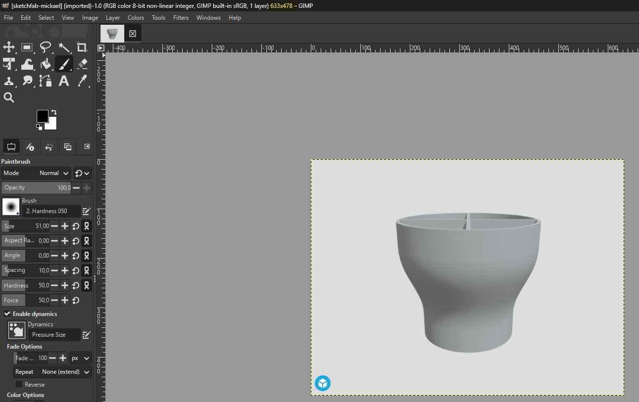
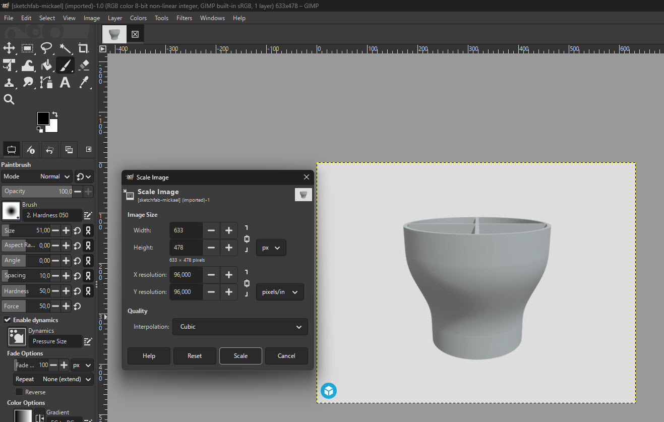
gimp According to their website, GIMP is a cross-platform image editor available for GNU/Linux, macOS, Windows and more operating systems. It is free software, you can change its source code and distribute your changes. GIMP provides you with sophisticated tools to get your job done. You can further enhance your productivity with GIMP thanks to many customization options and 3rd party plugins.
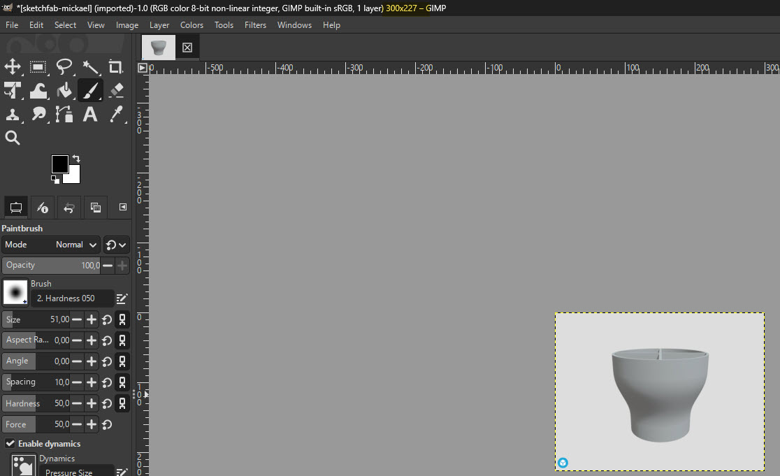
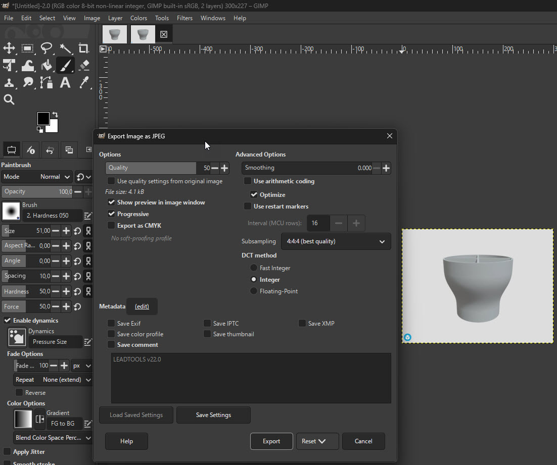
I followed the basic tutorials in their website for resizing dimensions, changing the file size and so on.
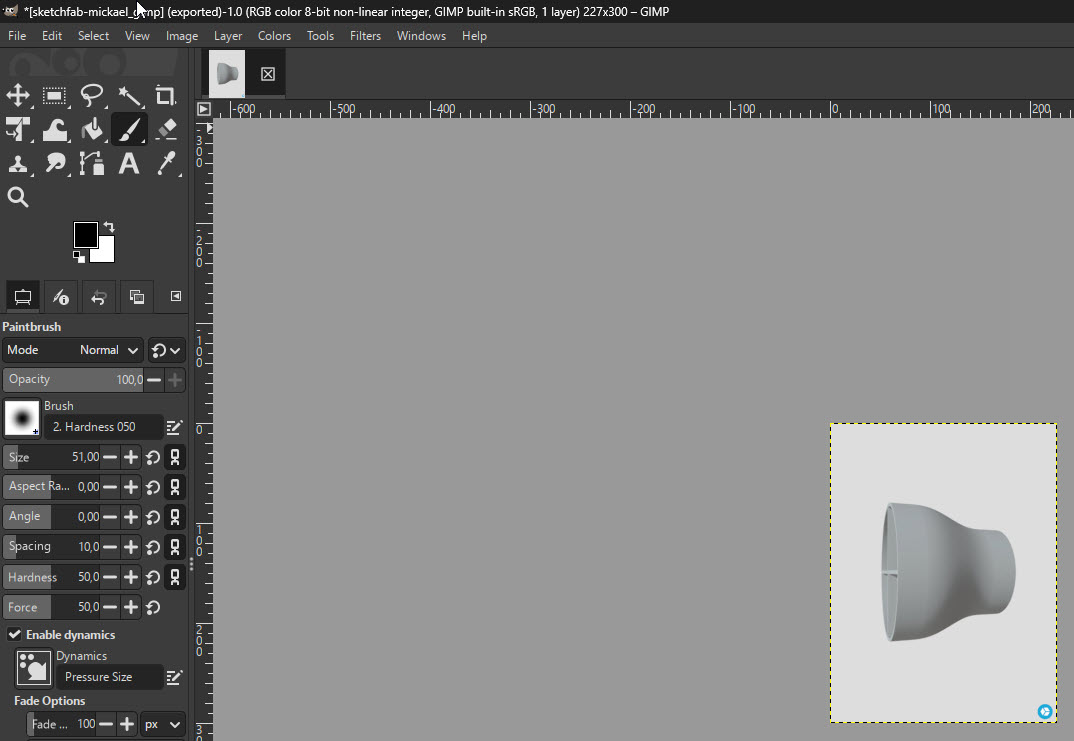
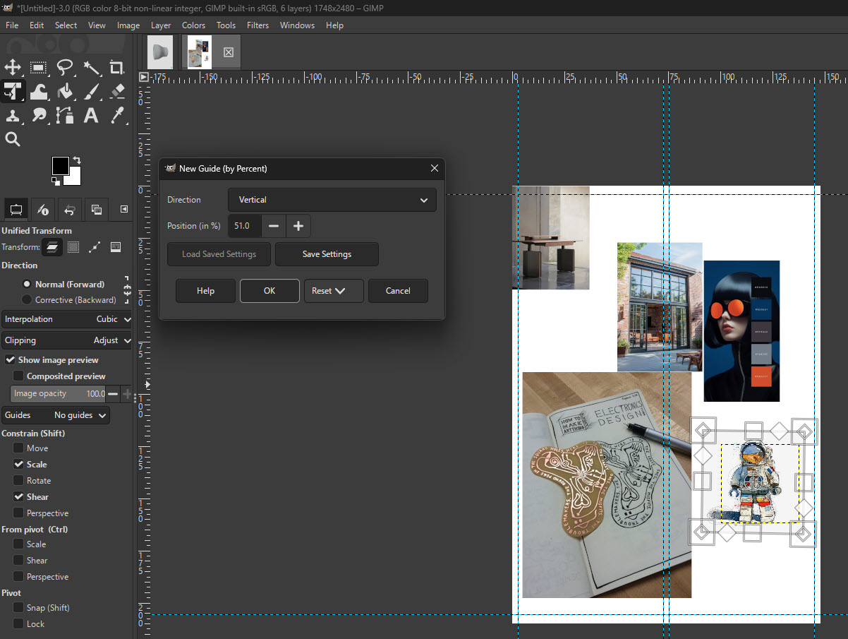
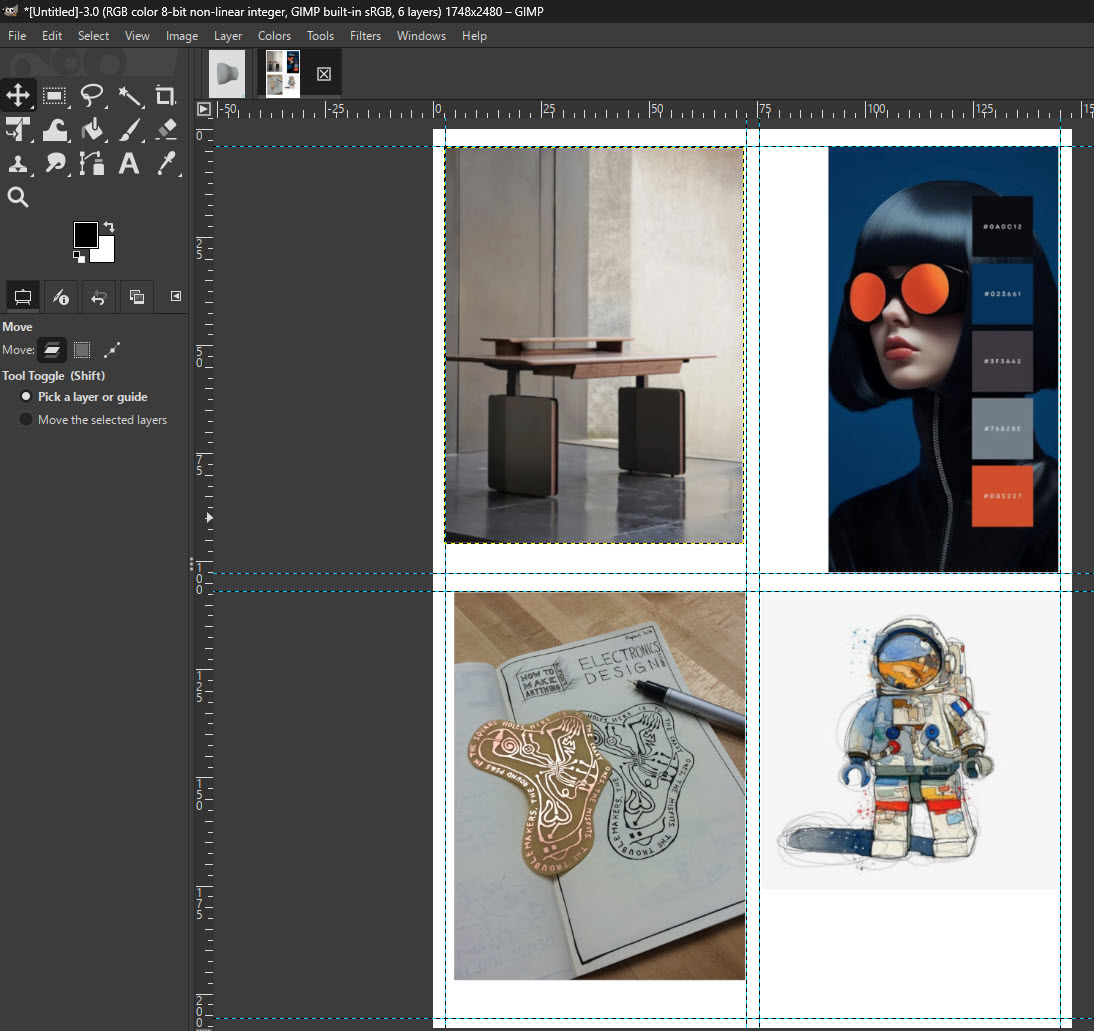
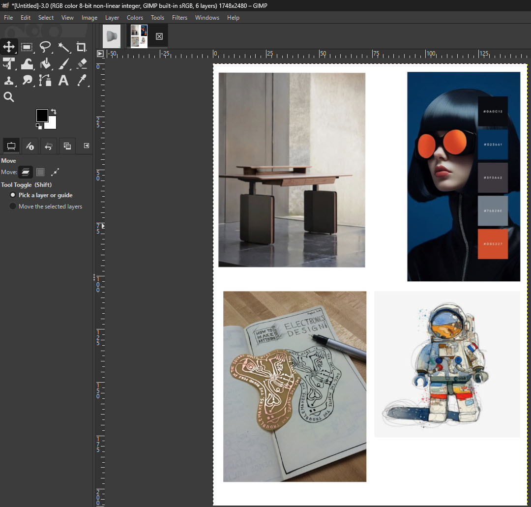
Then I decide to do something more creative, but still easy, so I looked for a creative tutorial in Youtube. This is the one that I chose. So for my collage I took some random pictures from Pinterest and this is my process.
Time to try another rasterizing software, also free. In this case it will be affinity Pixel.
[!Creative freedom from Canva.] Affinity comes with built-in Vector, Pixel, and Layout studios, but you’re not locked in. Rearrange panels and mix and match your favourite tools to build custom studios. You can save multiple setups, switch between them in a click, and even share with others or download theirs. It’s customization that flexes to your workflow.
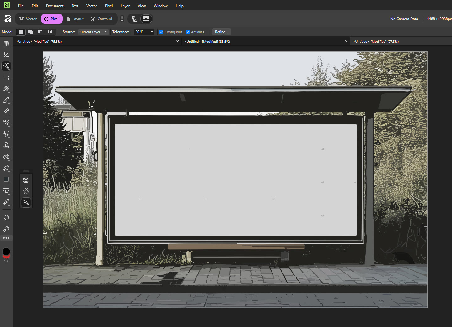
From this free image:
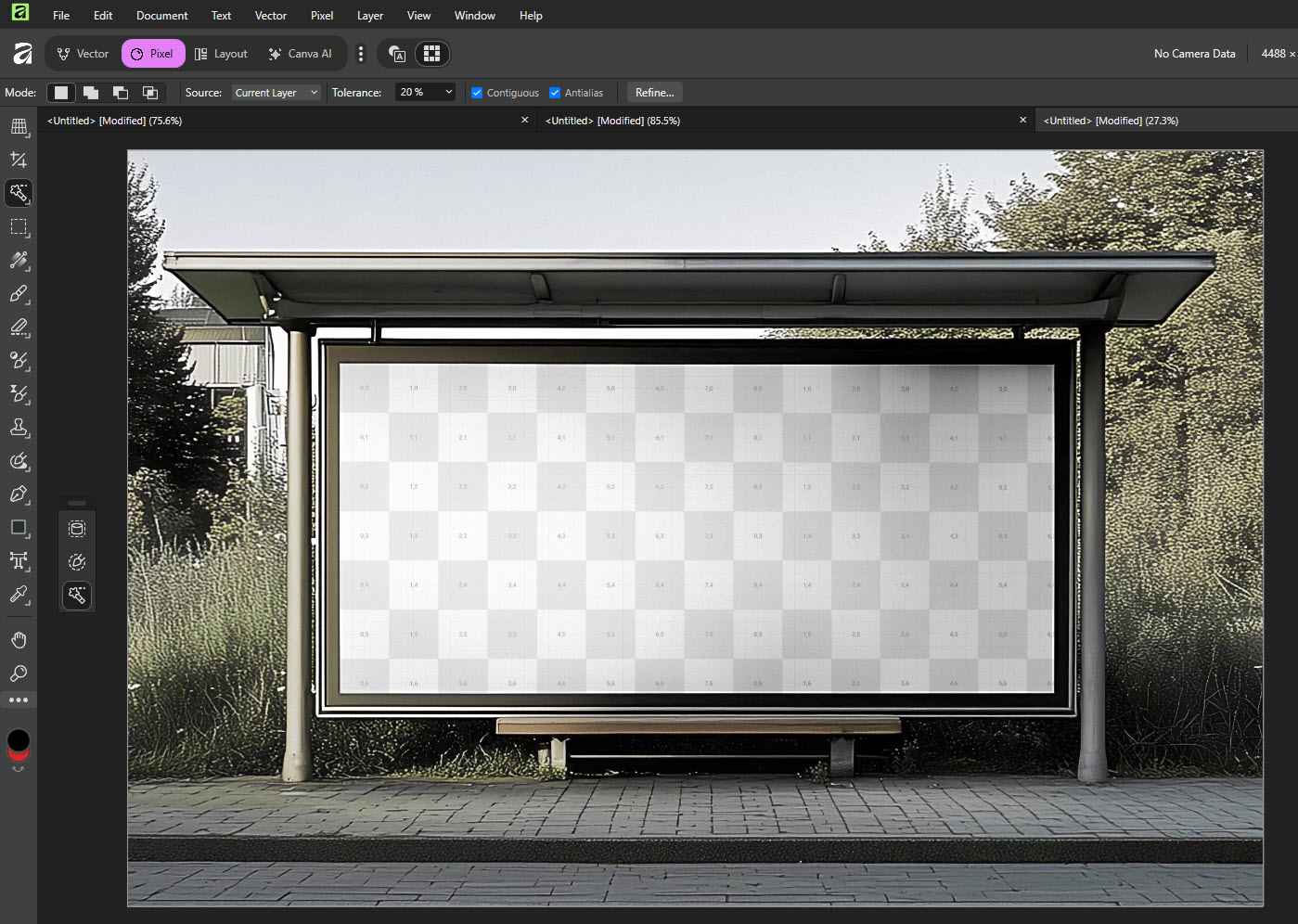
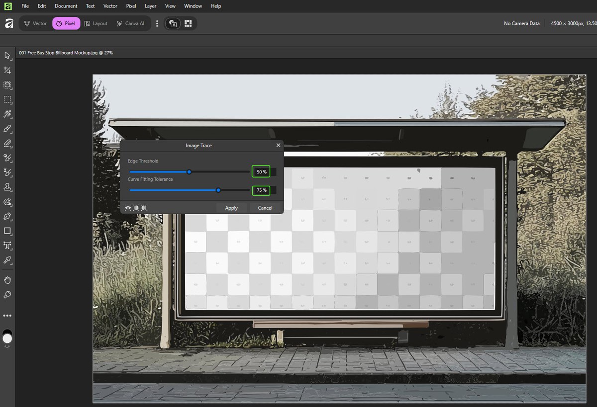
I converted into a vector image with the “Image trace” option.
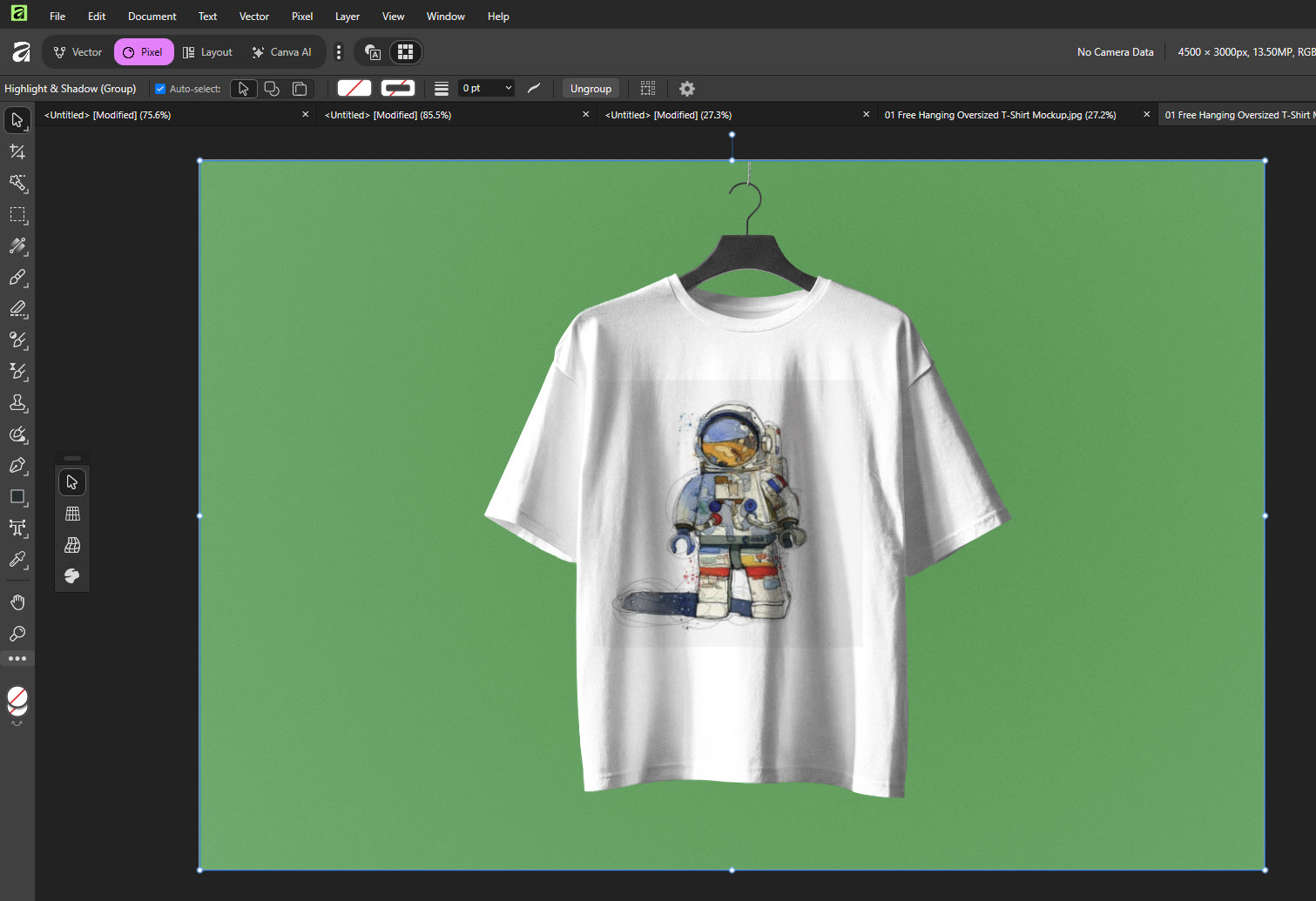
Then, I went for a little more interesting task inspired by this tutorial , creating a mockup for a T-shirt. From this:
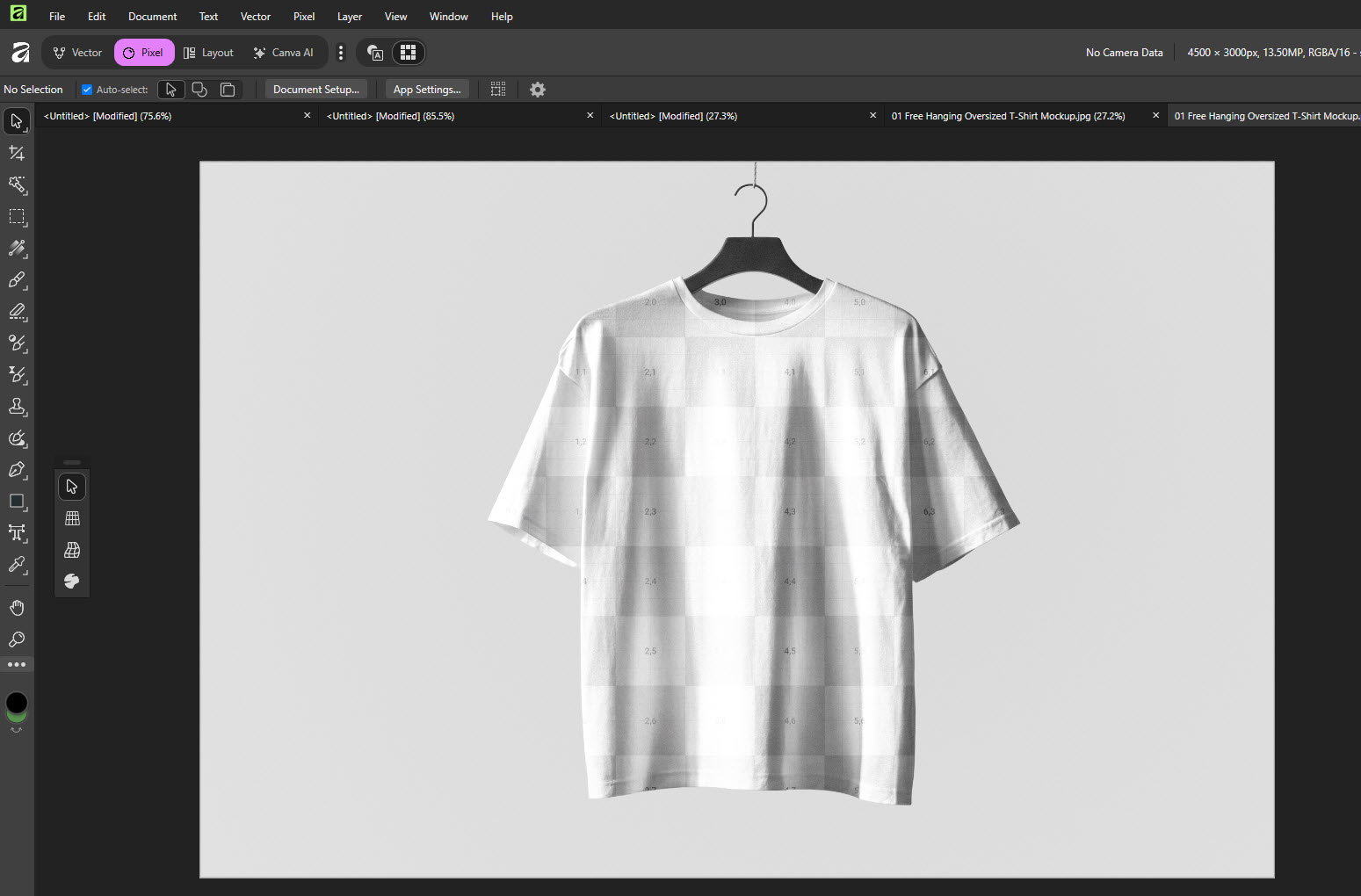
To this:
2D design - vector.
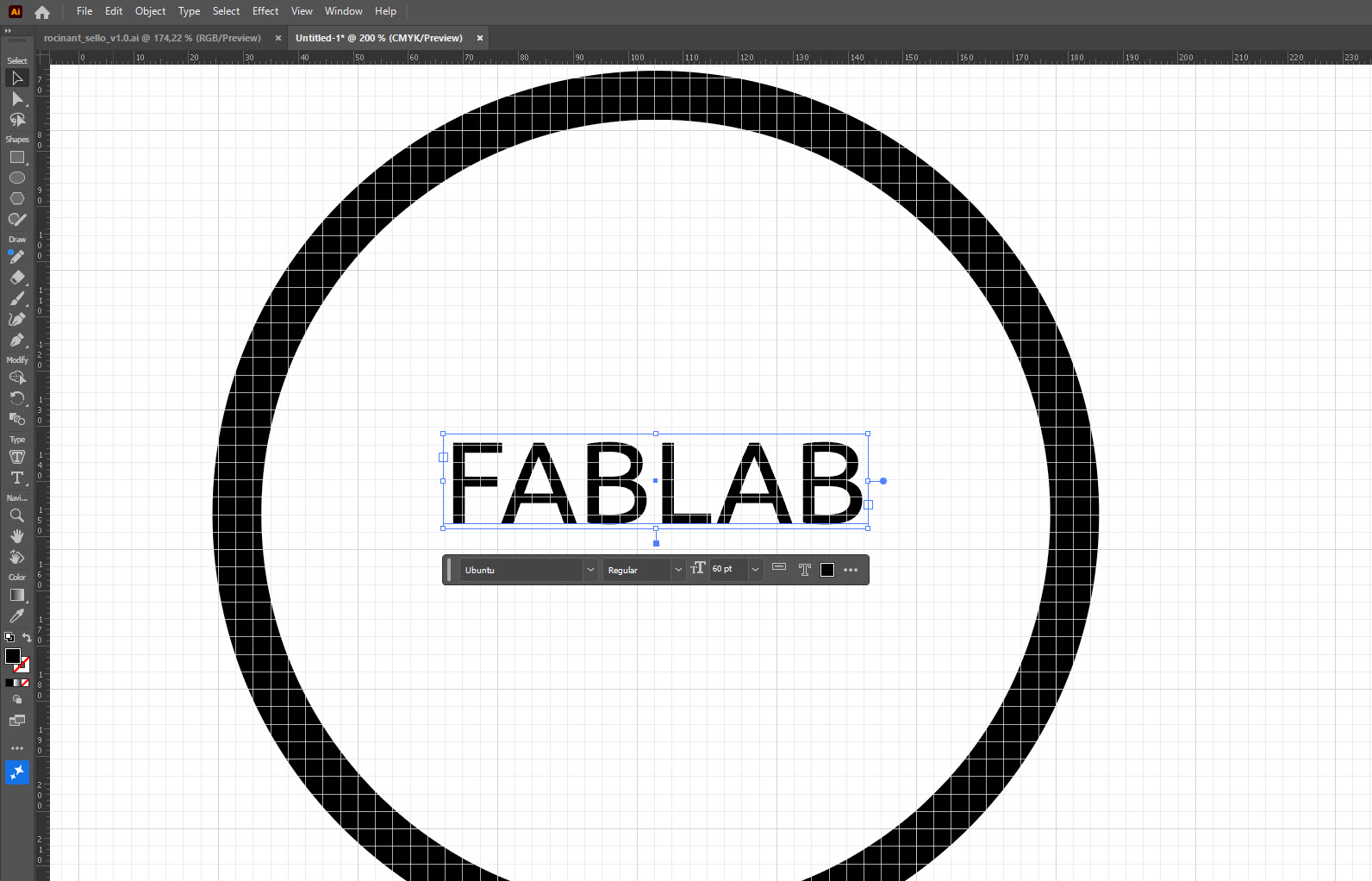
Adobe Illustrator. Adobe Illustrator is a great vector graphics editor and design software developed and marketed by Adobe.
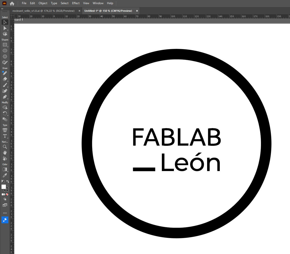
In a past life used to play around with Illustrator so I went straight and recreate one of the León’s Fablab logos:
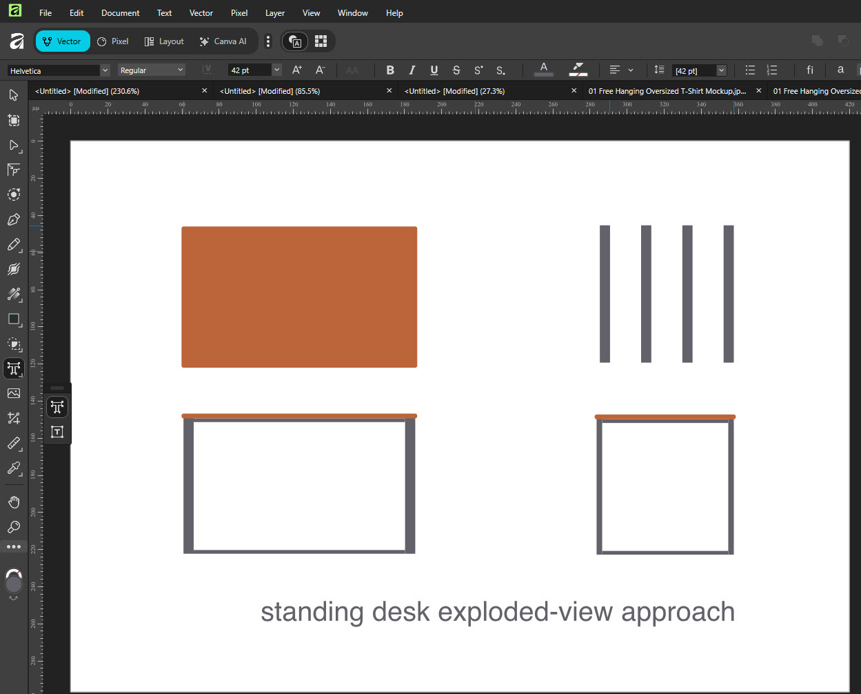
affinity affinity also offers a quite interesting substitute to Adobe Illustrator. Both programs share the similar shortcuts and ways to get the desired results. In this case I sketched a standing desk exploded-view.
3D design.
Autodesk claims that Fusion is the right tool to transform your anyone’s product development process with integrated design, manufacturing, electronics, and data management in a single solution.
Short before starting the Fab Academy I started a Fusion for makers course. It doesn’t mean I have much experience, but I don’t start from zero.
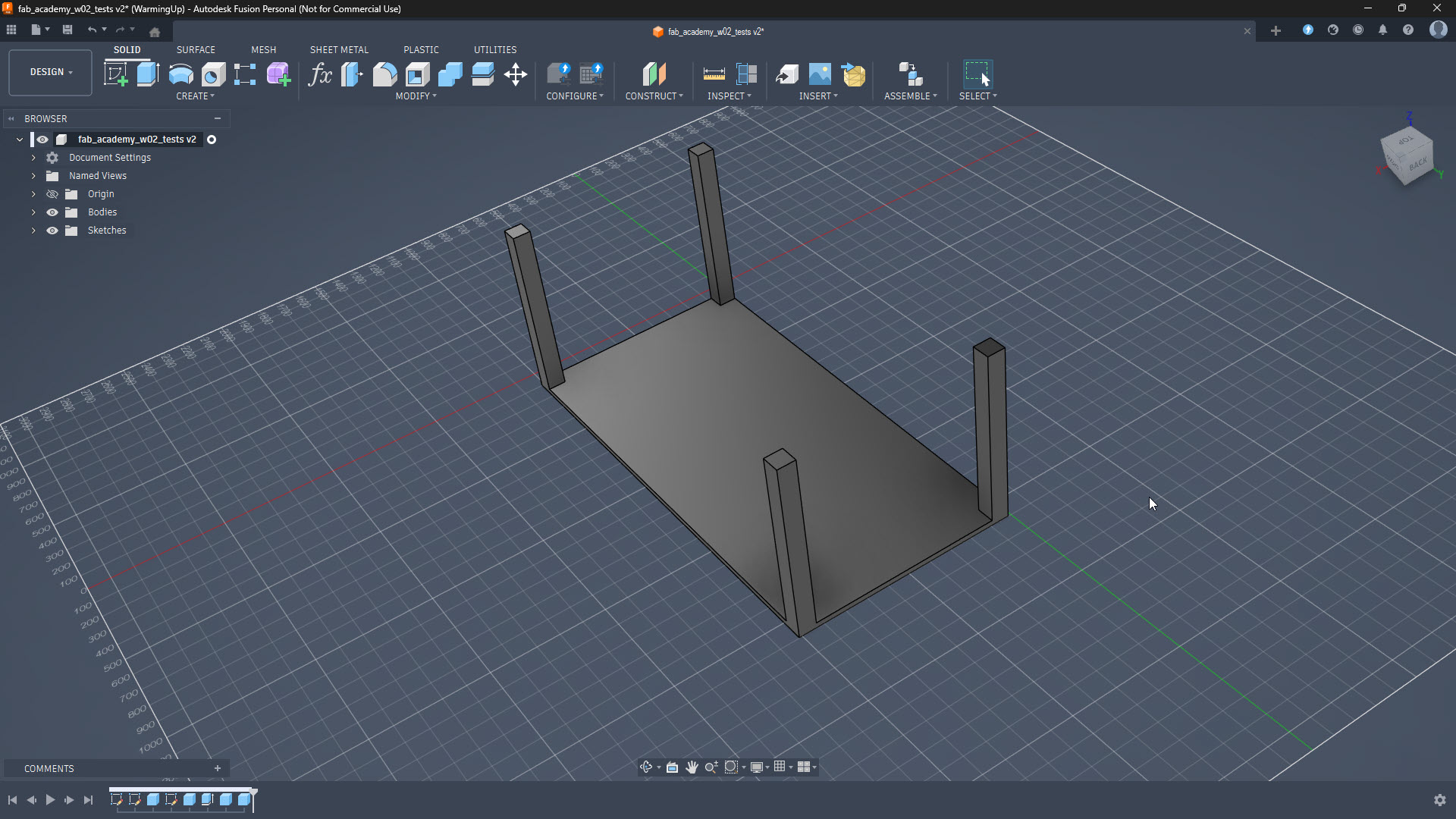
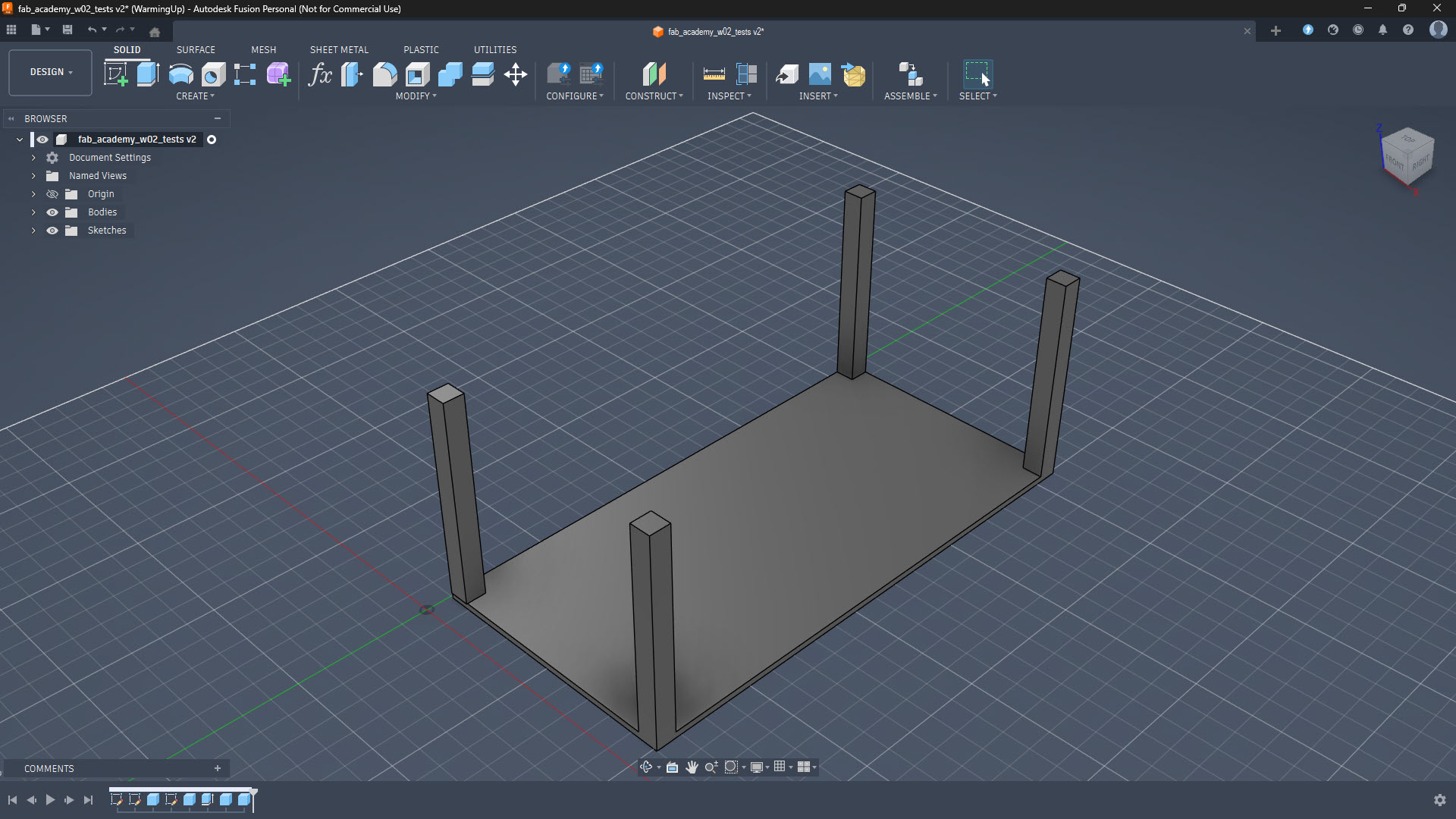
This is the basic figure I have done so far:
3D Animation
So far I have feeling quite comfortable with Fusion 360, so I am going to try this part of the assignment with the same software.
The goal is to create a simple animation showing a standing desk going up and down, with telescopic legs (two-stage, three concentric square tubes per leg). One thing that I realized or found out is that Fusion 360 animates components, not bodies. My current model consists of multiple bodies inside a single component, so every piece that needs to move independently must be its own component. In order to understand the difference between bodies and components in Fusion 360, I checked this video.
Let’s create the sliding legs and the correspondent animation!
Building the telescopic leg.
Each leg has three concentric square tubes:
| Tube | Section | Height | Purpose |
|---|---|---|---|
| Outer | 60×60 mm | 720 mm | Fixed to ground. |
| Mid | 50×50 mm | 400 mm | First extension stage. |
| Inner | 40×40 mm | 300 mm | Second stage, connects to tabletop. |
Process for one leg:
- Activate component (click on icon in Browser) → Edit In Place.
- New Sketch on XZ plane (use component’s own Origin, not the tabletop’s face — learned this the hard way, creates unwanted dependencies).
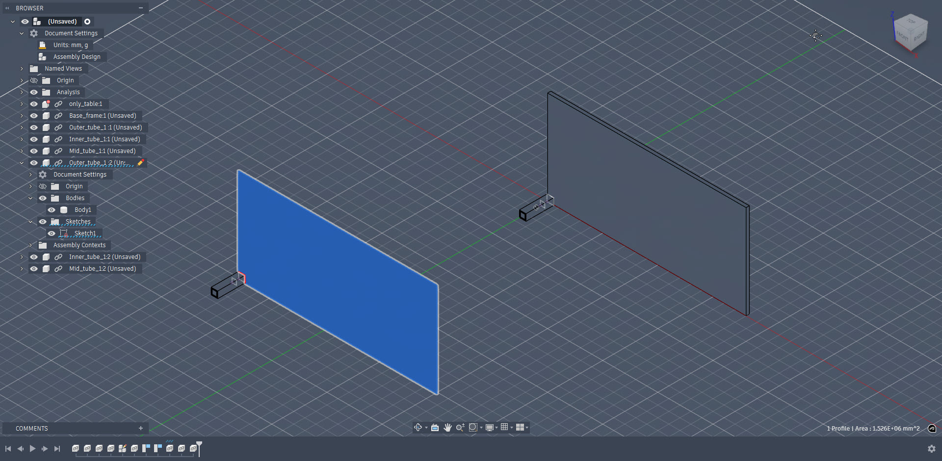
- Centre rectangle → Extrude.
- Finish “Edit In Place”.
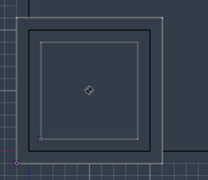
For concentric alignment: I use Move/Copy (M) with Point to Point mode — selecting centre of smaller tube’s face → centre of larger tube’s face.
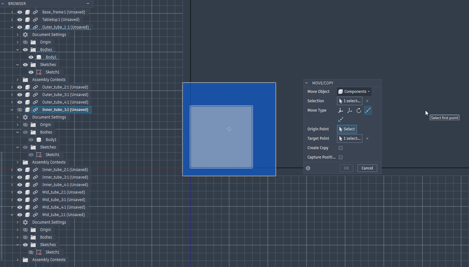
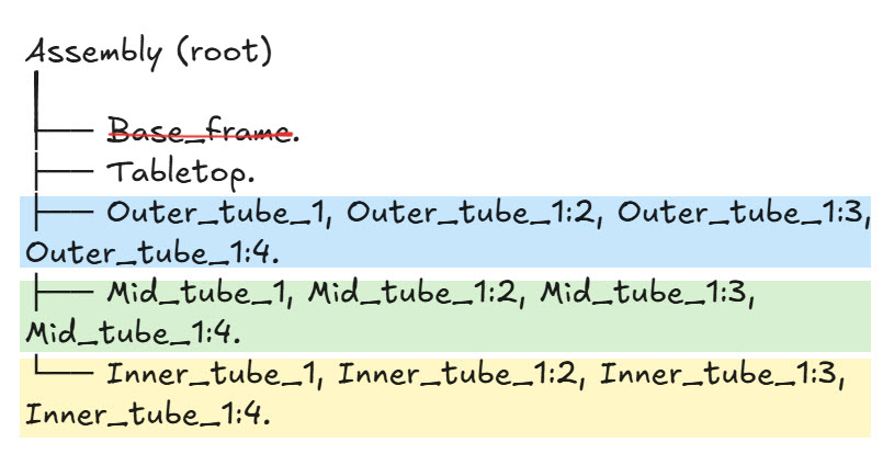
Copy to other corners: then I select the three tubes → Ctrl+C → Ctrl+V → Move to position. According to the information in the course mentioned above and a new one, editing one updates all because they’re linked instances ( Magic!! 🥳)
Setting up joints.
1. Ground the outer tubes.
Right-click each Outer_tube → Ground To Parent. This fixes them in space.
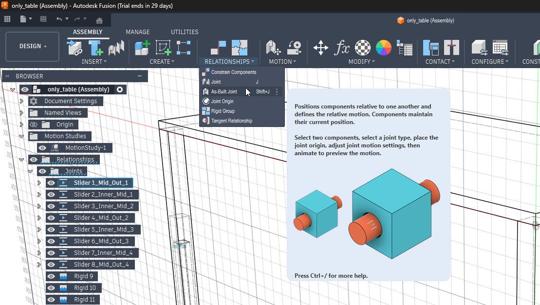
2. Create slider joints ( Win Shift+ J).
For each leg, two Slider Joints:
- Mid ↔ Outer: Assemble → As-Built Joint → select Mid first, then Outer → Snap on Outer’s top face → Type: Slider.
- Inner ↔ Mid: Same process, Inner first, then Mid.
Important: to prevent some weird behaviours, always select the moving component first, fixed component second. Otherwise the wrong part moves.
3. Set Motion Limits.
Right-click each Slider → Edit Motion Limits:
- Outer↔Mid: Min 0 mm, Max 320 mm
- Mid↔Inner: Min 0 mm, Max 220 mm
Don’t forget to tick both checkboxes or limits won’t apply.
4. Connect tabletop.
As-Built Joint between Tabletop and each Inner_tube → Type: Rigid (no snap needed, just keeps them together).
Animation.
First I tried with Motion Study, but it got weird with linked instances (probably my fault) So, after some digging in Google, I ended up using the Animation Workspace instead.
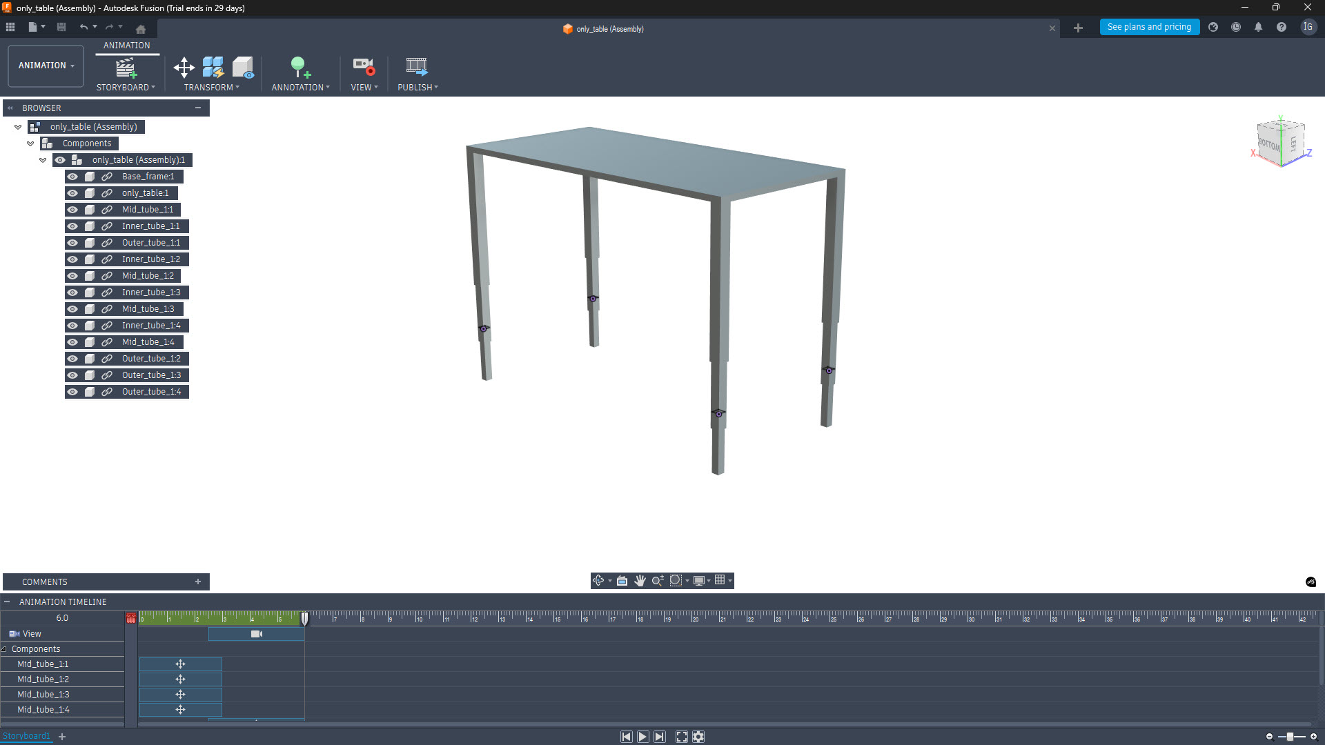
The tabletop moves automatically because of the Rigid joints with Inner_tubes.
Exporting video.
The basic steps in Fusion, once I was done with my animation, were:
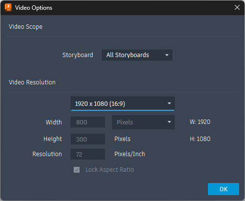
- Publish → Video Options.
- Resolution: 1920×1080 (there are other options for lighter files, but I wanted to see the size of this one).
- Export as AVI.
Compressing with FFmpeg.
As I had no prior experience with this software I checked their site and also asked Claude how to install:
*Show me how to install FFmpeg in Windows 11, using Powershell. Afterwards show me how to compress a video.
As winget wasn’t recognized in my system, I went for option 2:
If winget isn't recognized, use Option 2.

## Option 2 — Manual Installation

### Step 1: Download FFmpeg

1. Go to https://www.gyan.dev/ffmpeg/builds/
2. Download **ffmpeg-release-essentials.zip**
3. Extract to `C:\ffmpeg`

You'll end up with something like:

C:\ffmpeg\ffmpeg-YYYY-MM-DD-git-XXXXXXX-essentials_build\bin\ffmpeg.exe
### Step 2: Add to PATH
Open PowerShell as Administrator and run (adjust the path to match your extracted folder):
[Environment]::SetEnvironmentVariable("Path", $env:Path + ";C:\ffmpeg\ffmpeg-YYYY-MM-DD-git-XXXXXXX-essentials_build\bin", "User")After closing PowerShell completely, I reopen it, and run the :
ffmpeg -i "input_file.avi" -c:v libx264 -crf 23 -preset medium output.mp4That line compressed the 10 Mb file exported using Fusion to an insane compression of 146 KB.
Files.
Find below the files that I made for this assignment.
- Adobe Illustrator León’s Fablab logo. Download svg logo.
- affinity exploded table. Download svg exploded table file.
- Fusion 360 final table assembly. Download FBX model.
- Standing desk assembly. Download STL model.
After uploading these files I noticed that the León’s Fab Lab logo wasn’t showing the right font. So, after some digging in the Internet, I found a solution: transform the letters to outlines ( in Illustrator: Type → Create Outlines). Now it shows the original logo and, whoever works with this file in the future will not have to care about having those specific fonts.
Useful links and resources.
Thanks to one of my local instructors, Adrián Torres, I landed in this site from a former Fab Academy student, Mickael Pitarresi. Seeing how he embedded his 3D models using Sketchfab convinced me to do the same. I uploaded my own standing desk assembly and embedded it below (yes, cajeradeldia is me, one of my multiple identities 😁).
Some inspiration for the standing desk in Sketchfab:
- https://sketchfab.com/3d-models/standing-desk-65a7f4b06a5f4954a0d43eb8812dd165
- https://sketchfab.com/3d-models/electric-height-adjustable-standing-desk-0113b87dd9e74add81508d2f2dcd9d45
- https://sketchfab.com/3d-models/table-or-desktop-d17d85ec711c47cd80975ed7c55f3fb7
- https://sketchfab.com/3d-models/manual-desk-household-props-challenge-85d7116642174a2493c2b05067eae3bb
- https://sketchfab.com/3d-models/standing-desk-cd95fec5af6e48ffb6b0f2af476d37d0
- https://sketchfab.com/3d-models/mesa-com-regulagem-altura-eletrica-misch-f3357707af734da8b303b9bd2376b63d
- https://sketchfab.com/3d-models/standing-desk-cherry-wood-2b54ce8fdab949a3ada7027a8f066cb6
- https://sketchfab.com/3d-models/standing-desk-f5ee6902fd1e434da83ab665bdc03a5c
- https://sketchfab.com/3d-models/standing-desk-ae98e1742b7a4431997723895c7828f4
- https://sketchfab.com/3d-models/level-2-game-art-unit-12-model-71c5aac0fc604e0291a0c6d4890ed04d