FINAL PROJECT / DEVELOPMENT
- INTRODUCTION
- SCHEDULE
- CONSTRUCTION MATERIALS
- DESIGN AND FABRICATION
- PROJECT DEVELOPMENT
- Weekend 1
- Week1 25 - 28
- PCB Design and Fabrication Challenges
- Connector Strategy and Cable Management
- Assembly and Soldering
- Microcontroller Programming (RP2040)
- Week1 28 - 31
- Weekend 2
- Week2 1 - 7
- FUNCTIONAL TESTING AND VALIDATION
- FUTURE WORK & SCALABILITY
- ARDUINO CODE
- ORIGINAL FILES
INTRODUCTION
As I have described throughout the course, my SmartFlow ACS system by Aquanow allows the hot water pipes of any household installation to be preheated without the need to turn on the taps and wait for hot water to arrive while liters and liters of cold water go to waste.
By using SmartFlow ACS, hot water reaches the tap automatically while it remains closed, resulting in significant water savings.
The fundamentals of this system and its operation are detailed in the System Integration assignment.
SCHEDULE
Due to my biggest challenge throughout the course, all work related to the final project was delayed until two weeks before the presentation. Therefore, both the design and construction phases became a true marathon.
In fact, this documentation was compiled after the final project presentation and after receiving the approval from Neil.
CONSTRUCTION MATERIALS
Physically, the equipment is simple.
The two main components that make up the system are:
A Pump
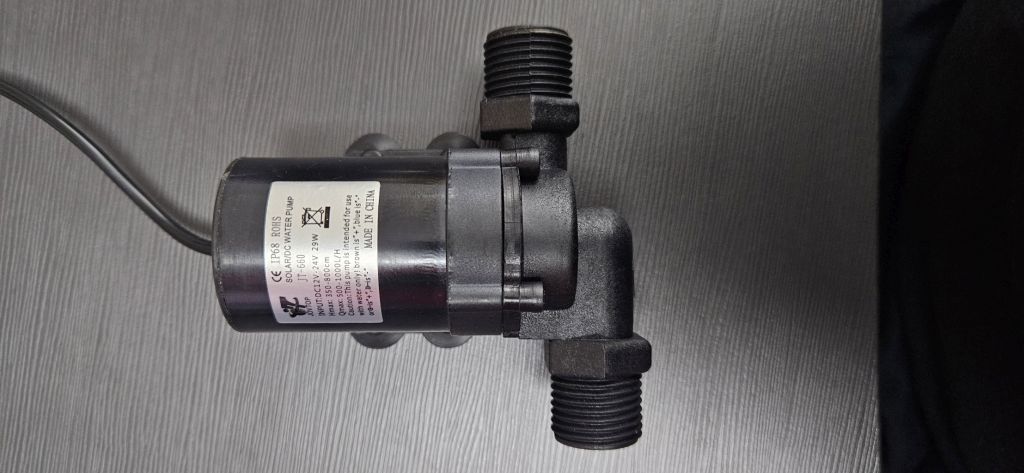
Which recirculates the water through the hot and cold water pipes.
A solenoid valve
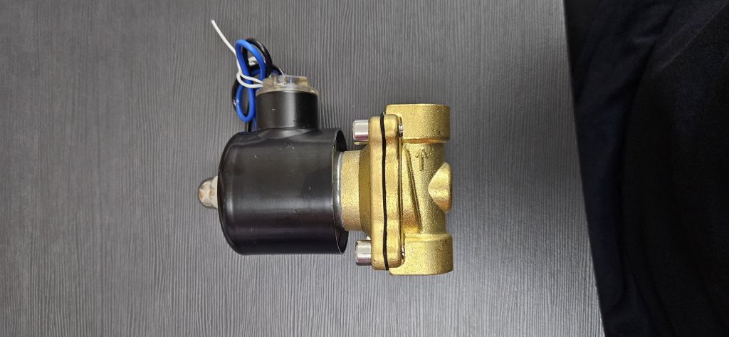
Which closes the connection between these pipes.
This point is crucial because by integrating the equipment into an existing installation, we are creating a by-pass between the hot and cold water lines.
If we only stopped the pump when the system is idle, the connection between both lines would remain open, which could result in hot water coming out of the cold taps or vice versa. This solenoid valve closes the communication between the two lines when the system is inactive, effectively eliminating the by-pass.
The remaining materials are used to control these two core units, such as the electronics, the remote control, and the temperature probe, as well as to house all the components, which is the purpose of the 3D-printed enclosure we will make.
A full breakdown of all components and their costs can be found in the System Integration assignment.
DESIGN AND FABRICATION
HYDRAULICS
The hydraulic section is the only part that was purchased commercially rather than fabricated in the FabLab.
Since the system works with hot water, these components must be completely watertight. Given the limited time available, it was decided to purchase off-the-shelf components and assemble them using Teflon tape.
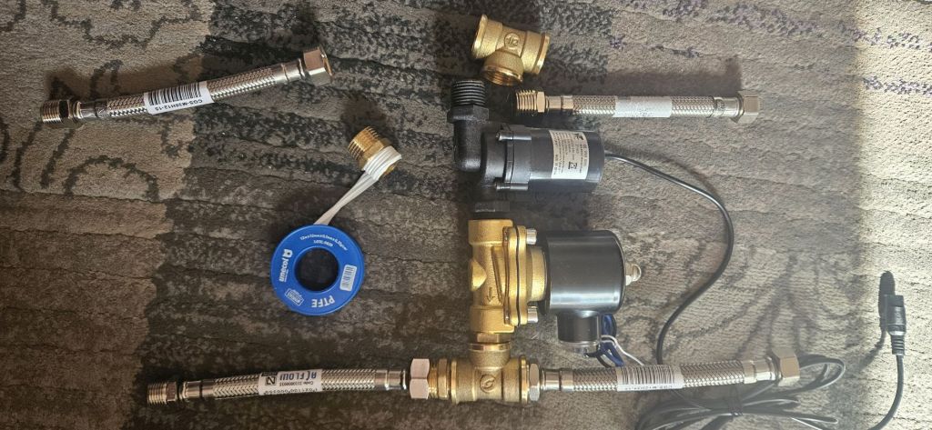
These components are:
- The pump
- The solenoid valve
- 2 hoses (1/2” male to 3/8” female)
- 2 hoses (3/8” male to 1/2” female)
- 2 hex nipples (1/2”)
- 2 tees (1/2”)
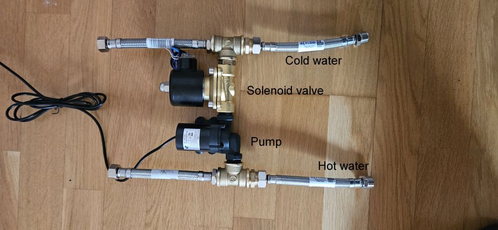
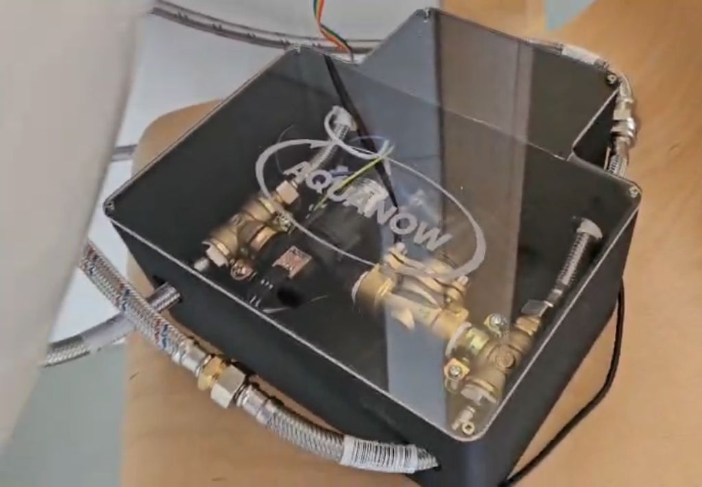
Once assembled, the hydraulic body forms a single, unified piece that will be secured to the enclosure housing the entire system.
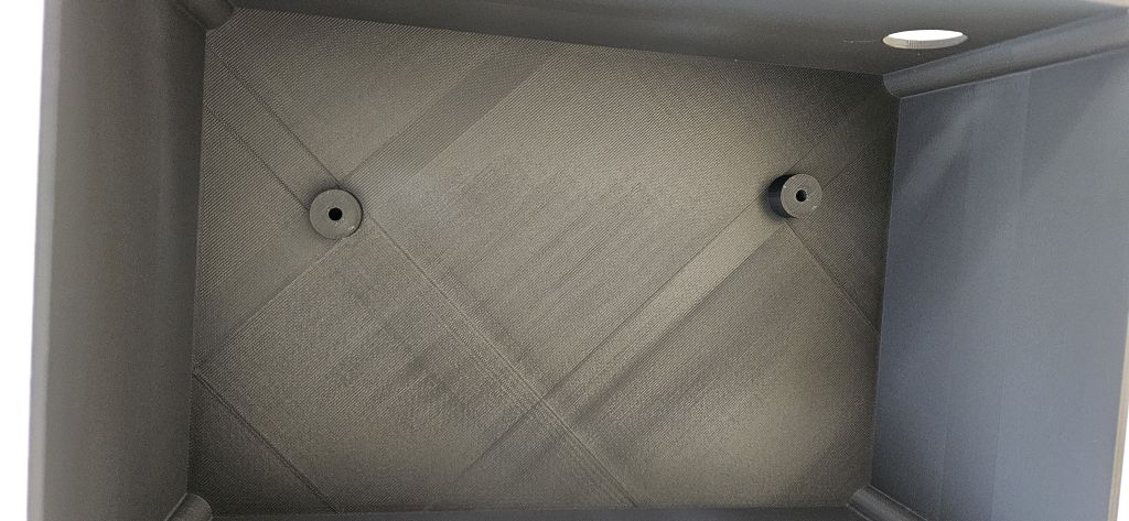
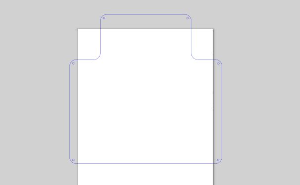
MAIN ENCLOSURE
The main enclosure is designed to house both the hydraulic and electronic components, creating a physical separation between them. The electrical section is positioned above the hydraulics to prevent any potential water leaks from affecting the electronics.
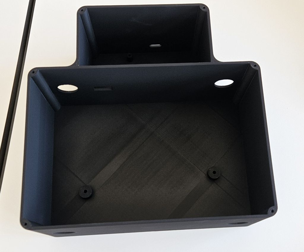
It is fabricated as a single piece using 3D printing with PETG filament to ensure mechanical strength. The design also incorporates bosses (mounting posts) to secure the hydraulic components using clamps fastened with screws, as well as to mount the electronic board with screws.
Openings are provided to route the wiring from the hydraulic section to the electrical section, along with cutouts for the water hoses to enter and exit, and a slot for the 24V DC power jack.
Additionally, an external opening is included for the XIAO RP2040 USB connector in case reprogramming is required in the future.
In future iterations, the plan is to implement guide rails to hold the electronic board instead of screws, as well as integrated clips in the enclosure body for more efficient cable management. Furthermore, the goal is to add rubber grommets around the water hoses and rubber plugs for unused openings, such as the USB connector slot.
The final enclosure design was done in Fusion due to the learning curve and time constraints I faced with FreeCAD, although the goal remains to continue working with FreeCAD.
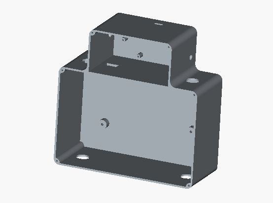
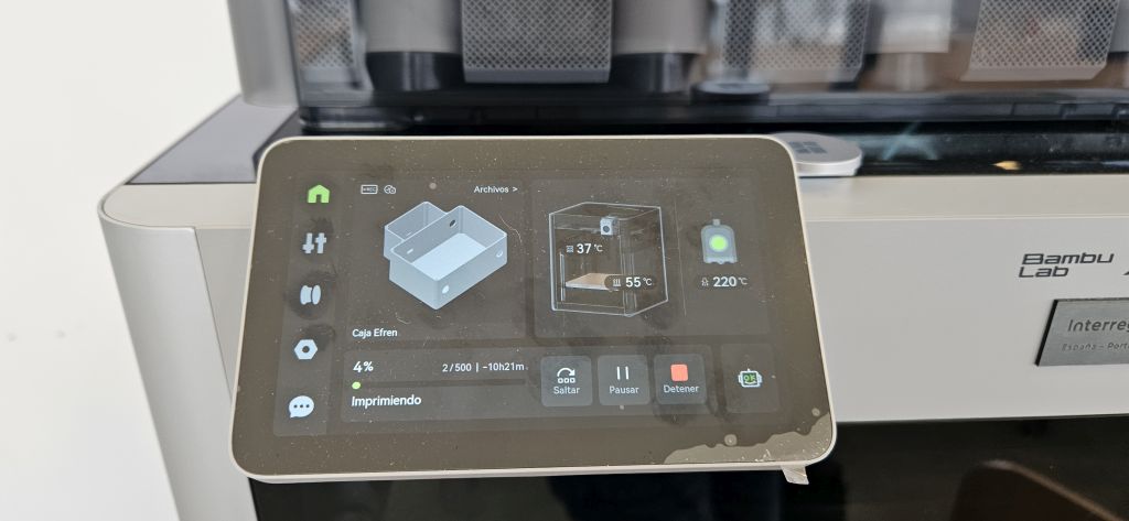
The printing was carried out on The Bambu, which was the only printer in the FabLab capable of printing a part of this size.
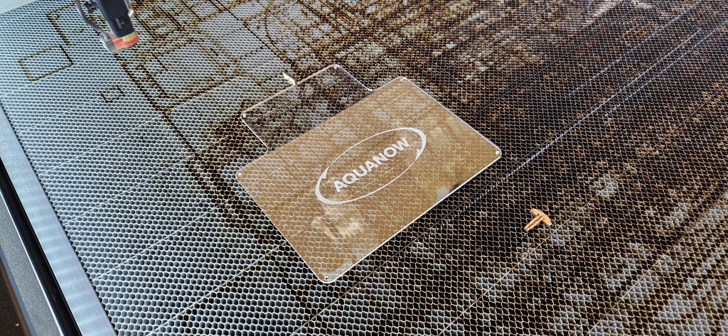
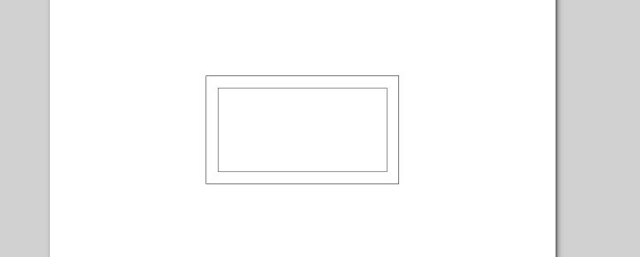
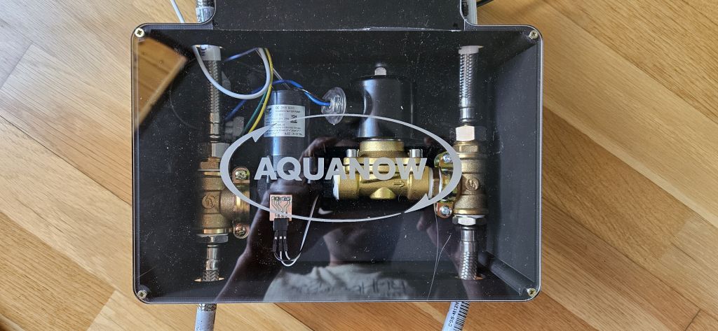
Finally, the entire assembly was covered with an acrylic lid engraved with the Aquanow logo. Both the cutting of the acrylic and the engraving were performed using the laser cutter.
The final result: A transparent lid featuring the brand logo, revealing the interior to better demonstrate its operation.
ELECTRONICS
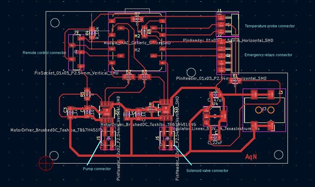
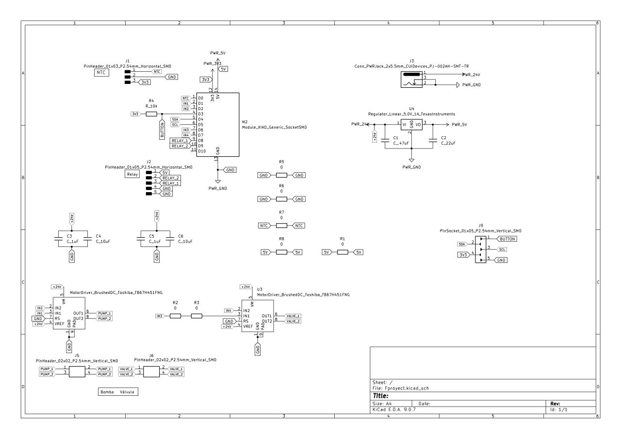
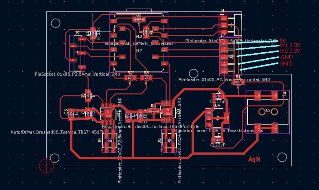
The electronics are designed using KiCad. Three electronic boards were designed and fabricated:
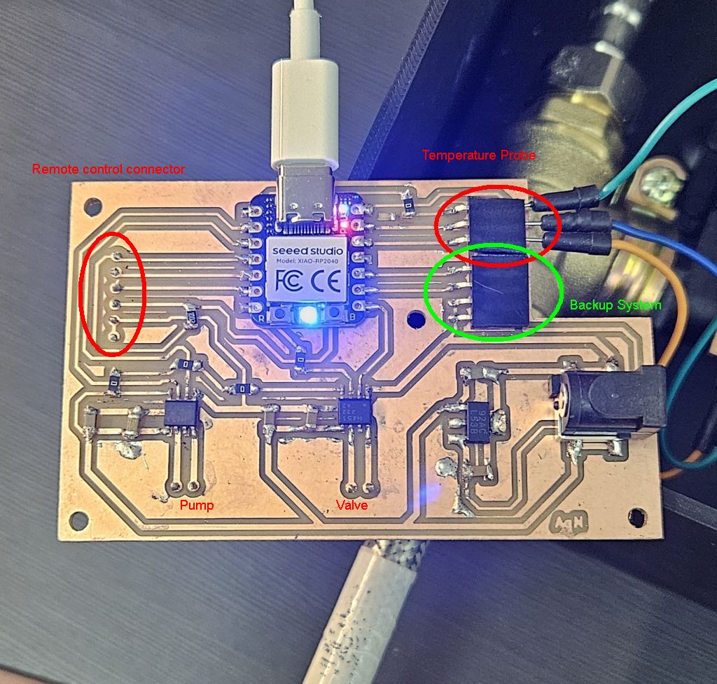
Main board
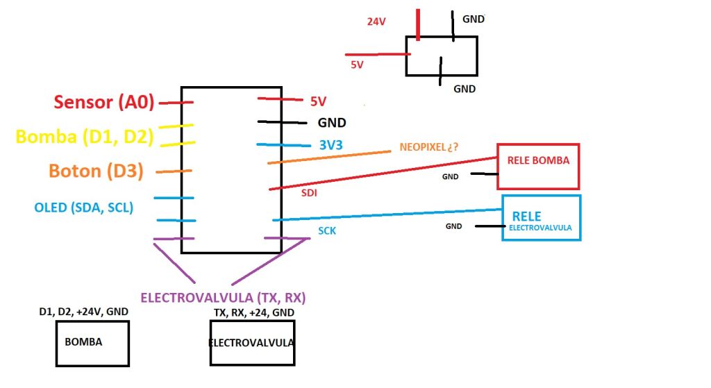
The main electronic board is the one placed inside the main enclosure alongside the hydraulics. This board incorporates a Seeed Studio XIAO RP2040 microcontroller and is responsible for controlling the entire operation of the system. Its tasks are:
- Provide power supply to all components.
- It features a DC jack to power the system with a 24V input voltage. This voltage drives both the pump and the solenoid valve through two Toshiba TB67H451FNG motor drivers.
- It also includes a Texas Instruments LM2940 voltage regulator to step down the voltage to the 5V required to power the XIAO RP2040.
- In turn, the XIAO generates the 3.3V needed to power the 0.96” OLED display integrated into the remote control unit used to manage the system.
- Interconnect all system components.
- The pump: Connected to the 24V output of the first driver.
- The solenoid valve: Connected to the 24V output of the second driver.
- The remote control: Currently utilizing a wired connection, although the next iteration will feature a wireless remote control. This remote control houses an OLED display to monitor the system's operating status and a start button to initiate the process.
- The temperature probe: Positioned on the water pump, it monitors the temperature of the water circulating through it, feeding this data back to the microcontroller for real-time decision-making.
- House backup/redundant systems.
- During the PCB design phase, a backup system was carefully planned in case the motor drivers failed. As detailed later, this design precaution proved to be extremely useful.
- Two additional pins from the RP2040 and a direct line from the regulator were routed to a dedicated connector to provide a 5V supply and logic signals from the XIAO. In the event of a driver failure, this setup allows for the connection of two external relays to power and control the pump and solenoid valve directly.
The following elements connect directly to the main electronic board:
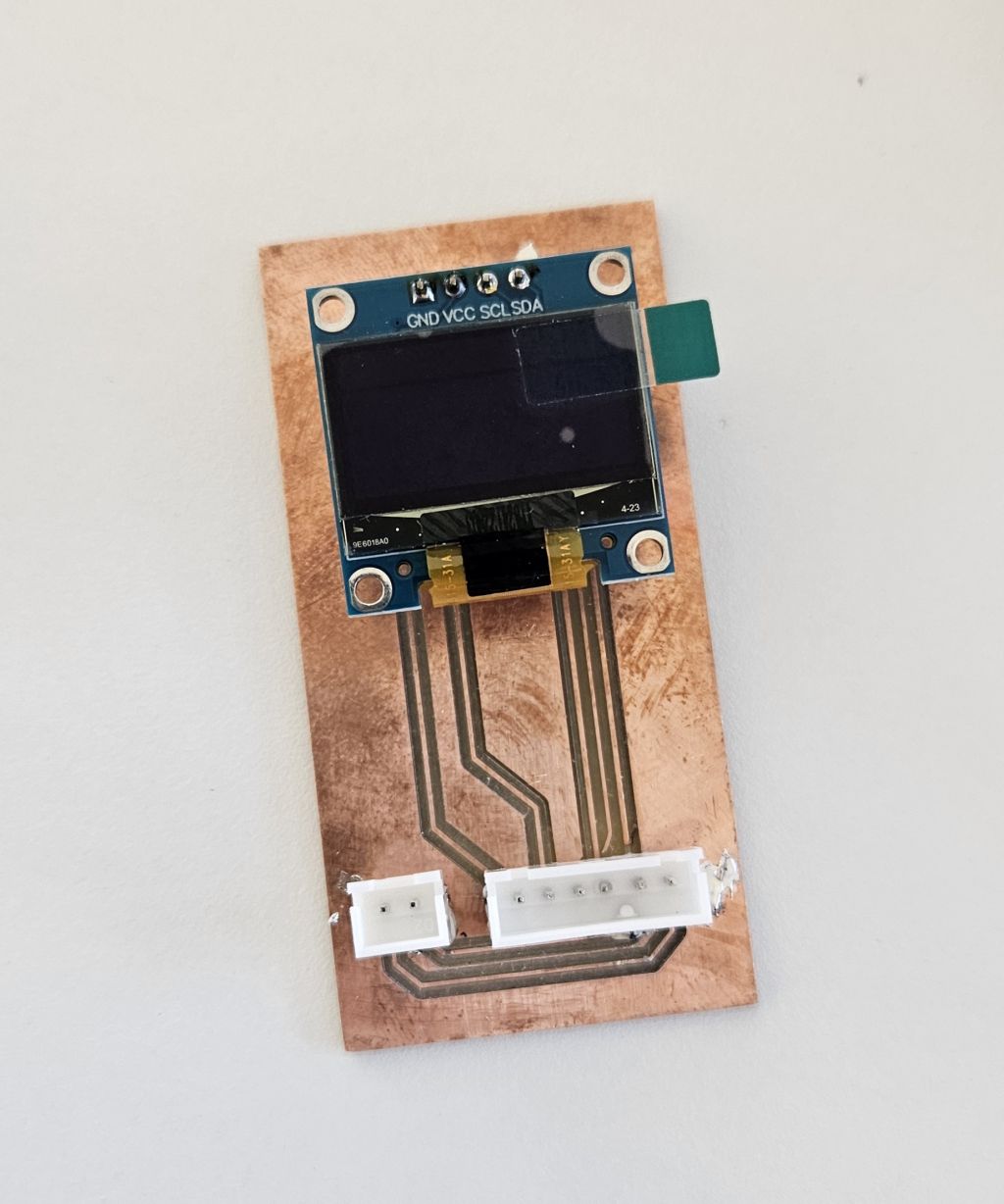
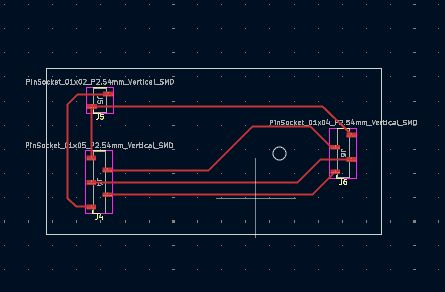
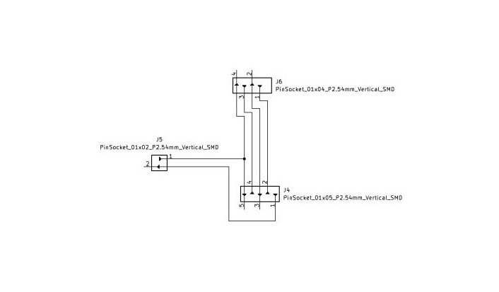
Remote control board
The sole purpose of this board is to provide physical support and to integrate the I2C communication lines for the OLED display and its power supply. It also routes the signal from the start push button located on the remote control unit.
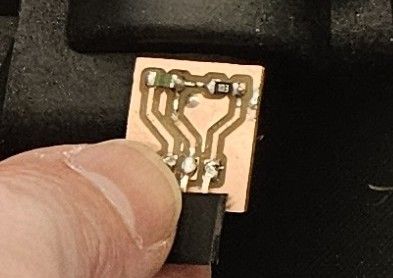
Temperature sensor board
This temperature board/module simply houses the analog NTC temperature sensor along with the 10K resistor required to take accurate temperature readings from the XIAO.
The signal output is placed between the sensor and the resistor, resulting in a typical voltage divider configuration.
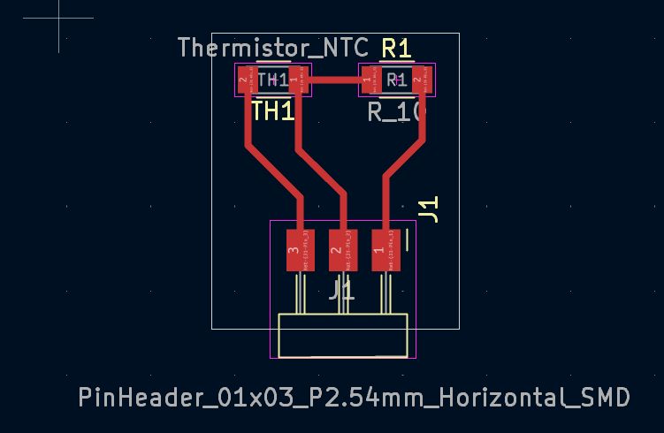
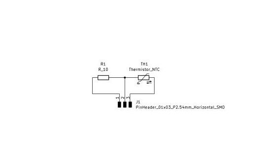
The component layout on the board follows this serial order:
- Power Supply Line: Connected to the regulated 3.3V from the board.
- NTC Probe: The first component of the divider. One end connects to the 3.3V line and the other connects to the central node.
- Signal Node (RP2040 Pin): The intermediate point between the NTC and the 10K resistor. From here, the trace/wire connects to the analog pin of the microcontroller.
- 10K Resistor: The second component (reference or pull-down resistor). It is connected between the central node and GND.
- Ground (GND): The circuit return path.
Since it is an NTC (Negative Temperature Coefficient) probe, its resistance is inversely proportional to the temperature:
- When the water is COLD: The resistance of the NTC is very high (much greater than 10K). Due to this high resistance, most of the voltage (the 3.3V) drops across the NTC. As a result, very little voltage reaches the central node (the RP2040 pin). The ADC will read a low value (close to 0V).
- When the water is HOT: The resistance of the NTC drops drastically (becoming much lower than 10K). Current flows much more easily through it, and the 10K resistor takes a more prominent role in the voltage divider. Consequently, the voltage at the central node increases. The RP2040's ADC will read a high value (closer to 3.3V).
REMOTE CONTROL
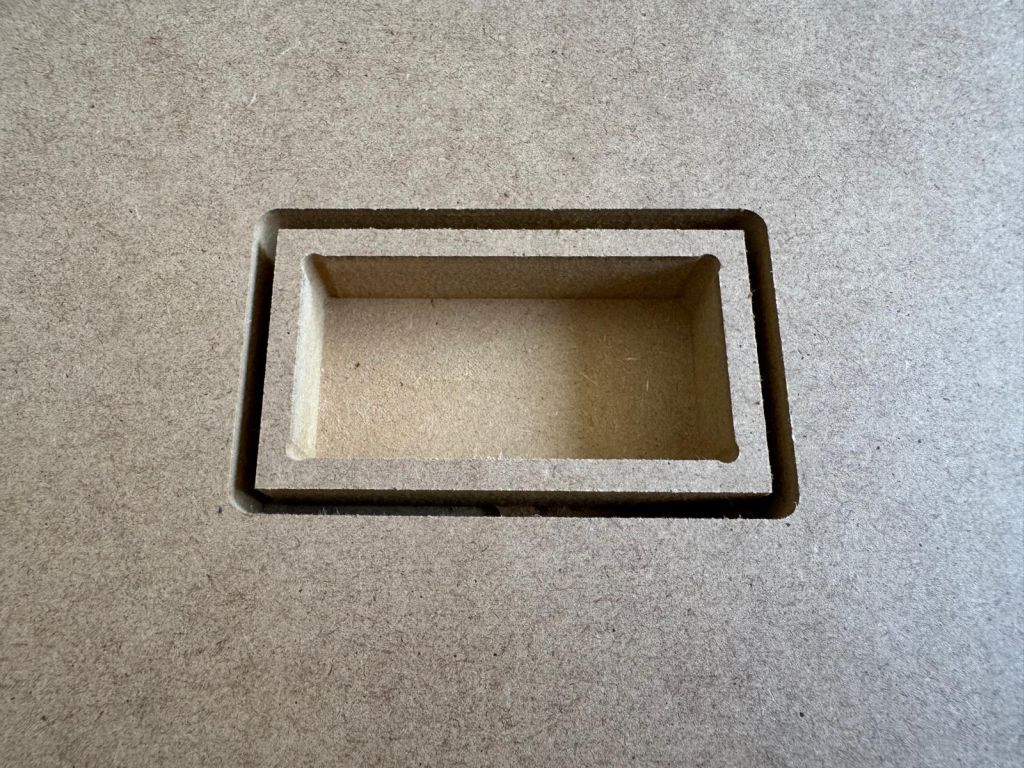
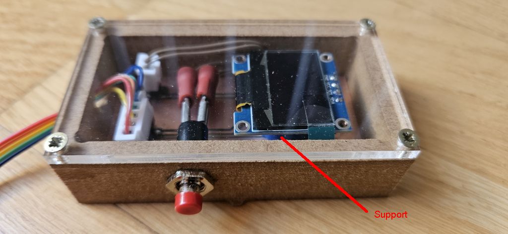
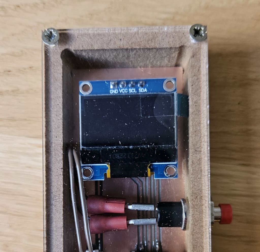
For the remote control, a pocketing technique was used by hollowing out a piece of wood to house the electronic board. This board serves as the mounting base for the OLED display and the start button.
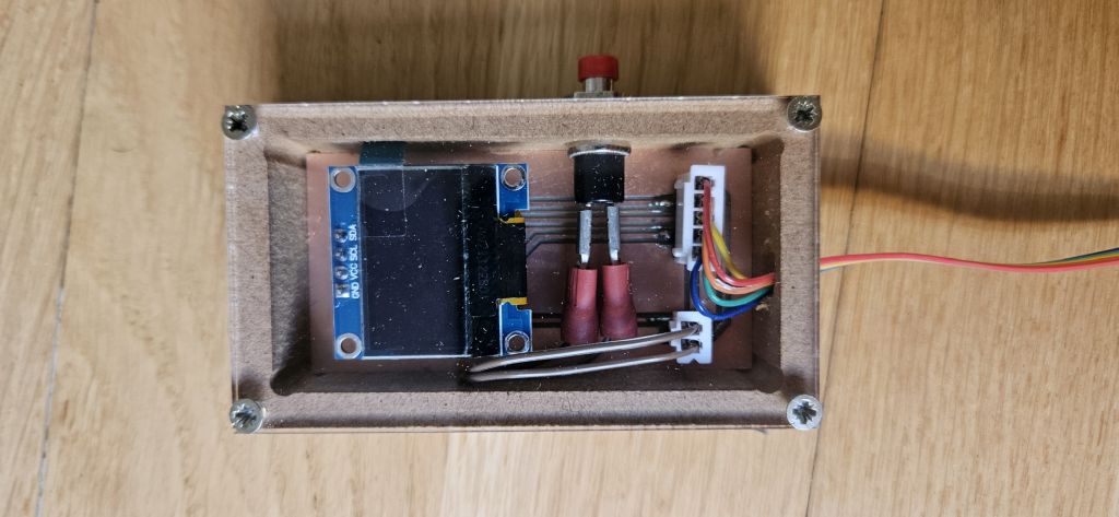
The board includes the connector for the cable coming from the main electronic board, which routes the 3.3V, GND, SCL, and SDA signals for the OLED display, as well as the button signal wire that pulls the pin to ground when pressed. Additionally, the board contains the dedicated connectors for both the button and the display.
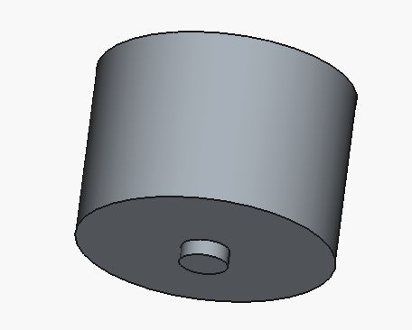
Beneath the display, a 3D-printed bracket was placed to prevent the screen from sinking into the enclosure.
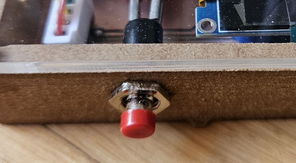
The button was mounted on the side, connected to the board's connector using small jumper wires.
The entire assembly was covered with a transparent acrylic plate to allow the interior to be fully visible, and this lid was secured to the wooden body using screws.
pull-up configuration. This setup was chosen over a pull-down configuration for safety reasons. In a pull-down setup, the wiring would be constantly energized, meaning any damage to the cable could short the XIAO's 3.3V pin directly to ground. Conversely, with a pull-up configuration, the energized line remains on the main PCB, and the line running to the remote control only serves to connect to GND when the button is pressed. As a result, any damage to the cable would simply cause a malfunction, but never a short circuit in the microcontroller.
PROJECT DEVELOPMENT
Weekend 1
Hydraulic System Assembly
- Timeline: May 23rd – May 24th
- Objective: Assemble and prepare the fluid dynamics subsystem for the water recirculation loop.
The initial phase of the project focused entirely on the hydraulic architecture. To ensure reliable operation, commercial-grade components were selected and assembled.
- Sealing & Fitting: All threaded connections and joints were meticulously sealed using PTFE tape (Teflon) to guarantee a completely watertight system and prevent any potential leakage within the prototype.
- Adaptability & Extension: In addition to the pre-assembled hoses included with the core equipment, four extra flexible hoses (latiguillos) were integrated. This modification extends the reach of the internal plumbing, significantly simplifying the installation and connection process to any standard domestic faucet or water outlet during testing and final deployment.
- Pressure & Leak Testing: Once the hydraulic assembly was completed, a preliminary verification test was conducted. The system's inlet ports were connected directly to the water supply network, while the outlet flexible hoses were sealed using temporary plugs. This setup allowed the system to be pressurized, successfully verifying the integrity of the joints and ensuring there were no leaks before proceeding with the electronics integration.
Week1 25 - 28
Electronics Design & Production
- Timeline: Week 1, May 25th - May 28th (Following Hydraulic Assembly)
- Objective: Design, mill, populate, and program the custom PCBs for the control system based on the RP2040 microcontroller.
PCB Design and Fabrication Challenges
Three distinct boards were designed using KiCad, leveraging the standard components available in the official Fab electronics library
While the temperature sensor breakout board was milled without issues, the other two boards presented significant fabrication challenges:
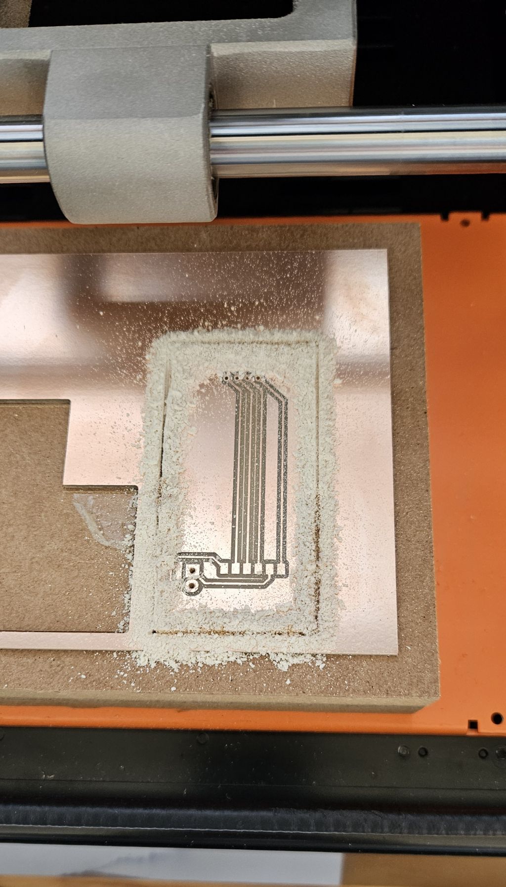
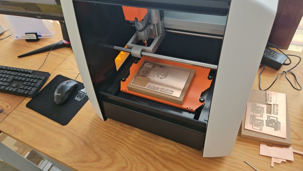
- Machine Reliability: The lab's Roland SRM-20 milling machine experienced ongoing precision and calibration issues throughout the process, requiring multiple attempts to get clean traces.
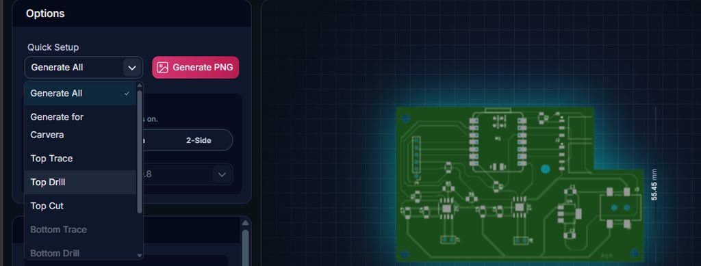
- Software Inversion Bug (gerber2png): A recent update to the gerber2png software caused a critical error during the drilling layer generation. The tool inverted the black and white color logic, resulting in massive, oversized holes that ruined the initial boards.
- Technical Reminder: In the software, for the Traces layer, the machine mills away the black areas and leaves the white geometry. However, for cutting and drilling layers, the machine cuts along the black paths.
- Solution: To avoid this inversion glitch, the best practice now is to strictly rely on the summary configuration panel located on the left side of the software interface.
- Reference: The complete step-by-step design and milling workflow can be reviewed in detail in my Electronic Production Assignment
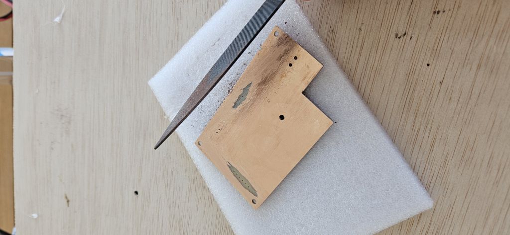
After adjusting the bed leveling and selecting two specific milling cutter, a 0.4 mm bit for routing the traces and a 0.8 mm bit for the drills and outline cut, we successfully completed the milling process
0.78 mm instead of 0.8 mm. If a larger or exact diameter is selected, Mods might skip some holes entirely. This happens because the physical holes are roughly the same size as the tool; if the generated .png file renders a hole even slightly smaller than the specified endmill diameter, the software's algorithm will assume the tool cannot fit and will refuse to calculate the toolpath. By defining the tool as 0.78 mm, we provide that tiny safety margin required for Mods to process and execute all the drill holes successfully.
.jpg)
.jpg)
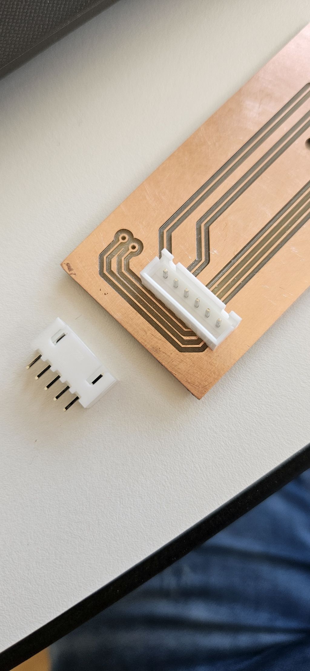
Connector Strategy and Cable Management
Selecting the right connectors was crucial to balancing ease of maintenance with electrical safety:
- Power and Communication: Vertical connectors were selected for both the main power inputs and the remote control communication cable. This ensures a secure connection capable of handling the system's current throughput.
- Sensors: Horizontal connectors were designated exclusively for the temperature probe lines.
- Error Prevention (Poka-Yoke): Specialized crimp terminals were attached to all custom cables. By combining vertical and horizontal profiles, the physical interface prevents any accidental cable inversion or incorrect cross-connections when plugging or unplugging the remote control unit.
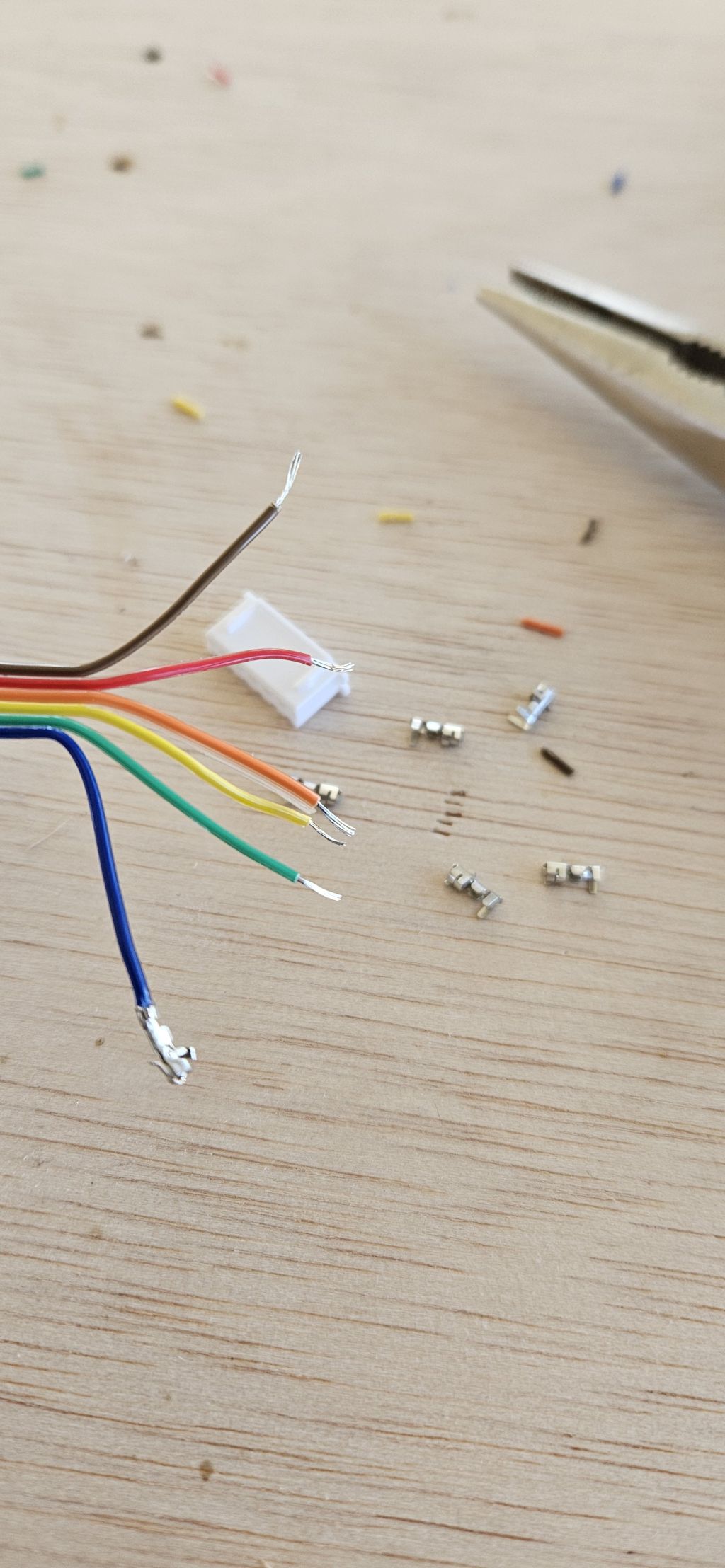
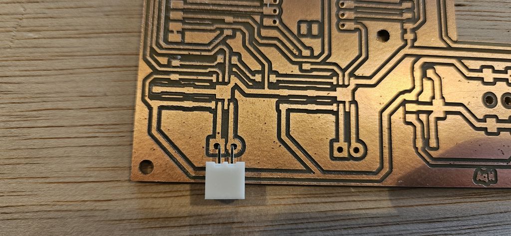
Assembly and Soldering
Once the PCBs were successfully routed and cleared of manufacturing defects, all surface-mount and through-hole components were populated using a high-quality soldering iron, standard solder wire, and meticulous patience.
.jpg)
.jpg)
Microcontroller Programming (RP2040)
With the hardware fully populated, the workflow transitioned to flashing the core firmware onto the RP2040 chip:
- Code Generation: Generative AI tools were utilized to assist in drafting the specific control algorithms.
- Logic Integration: Because the operational state machine and communication protocols had already been developed and validated during the System Integration Assignment, implementing and adapting the logic to the final hardware architecture was direct and efficient.
Week1 28 - 31
Enclosure and Housing Design
- Timeline: Week 1 May 29th – May 31st
- Objective: Design and fabricate the main housing and the remote control unit
During this stage of the project development, the main goal was to design and manufacture the physical enclosures for both the main system and the remote control unit.
This involved precise 3D modeling to accommodate the custom PCBs, routing for wiring, and ensuring a functional, clean setup for the final assembly.
As previously described, the main enclosure was designed in Fusion 360, taking advantage of the milling times from the previous PCB fabrication.
At the same time, the remote control unit did not require a highly elaborate 3D design; since it was manufactured using the CNC pocketing technique, only two rectangles sketched directly in Inkscape were needed.
The covers for both elements were also created in Inkscape, as they were purely 2D designs.
In terms of materials, PETG was selected for the main enclosure due to its durability and thermal resistance. The remote control unit was machined out of wood using the CNC router, while the covers for both components were laser-cut from acrylic (plexiglass).

Milling process of the remote control unit and final result.
Weekend 2
Testing and Troubleshooting
- Timeline: May 30th – May 31st
- Objective: Functionality verification. Driver Failure and Relay Contingency System
Testing began by powering the custom PCBs using the 5V supply from the Seeed XIAO RP2040 itself. The initial results were fully satisfactory. However, the moment 24V was introduced through the DC power jack, the left motor driver instantly blew up.
This was a major setback in the project’s development timeline. With time running extremely tight, remanufacturing the entire board from scratch was highly problematic, and the exact cause of the failure was not immediately clear.
Fortunately, as previously mentioned, a backup contingency system had been integrated into the PCB design. By utilizing alternative GPIO outputs from the XIAO, it was possible to control two onboard relays.
These relays stepped in perfectly to manage the pump and the solenoid valve, the only two components affected by the driver failure. The rest of the control electronics continued to function flawlessly.
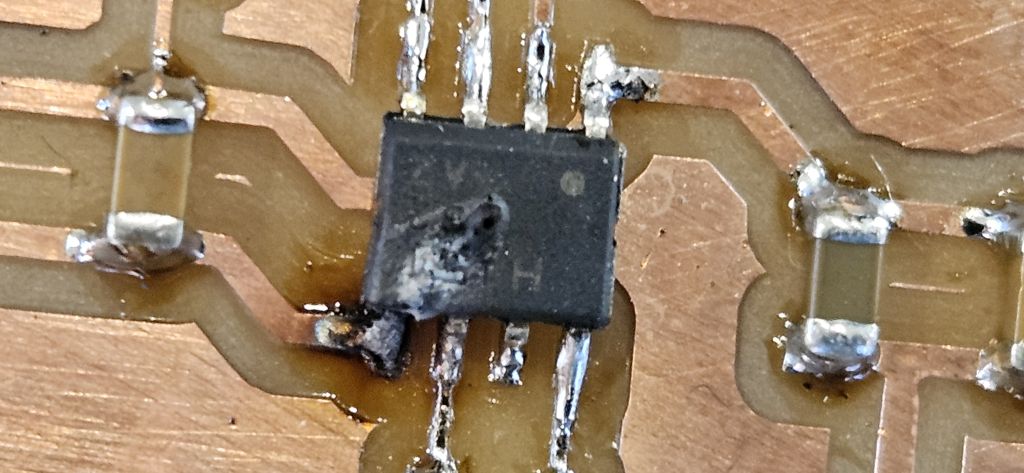
Root Cause Analysis
After carefully analyzing the driver’s datasheet and technical documentation post-incident, (TOSHIBA´S DATASHEET) the exact cause of the failure was identified.
To integrate the drivers into the board layout and map the pinout, multiple reference designs were followed alongside the official datasheet, but a critical detail was overlooked: the absolute maximum voltage tolerance for the Vref pin is 5V.
In the reference documentations consulted, the Vref line was tied directly to the Vm (motor voltage) track because those specific projects operated entirely on supplies under 5V.
This design choice was replicated on the custom board without anyone at the Fab Lab noticing the oversight during review. Consequently, when 24V was injected into the circuit, it rushed straight into the Vref pin, instantly destroying the driver.
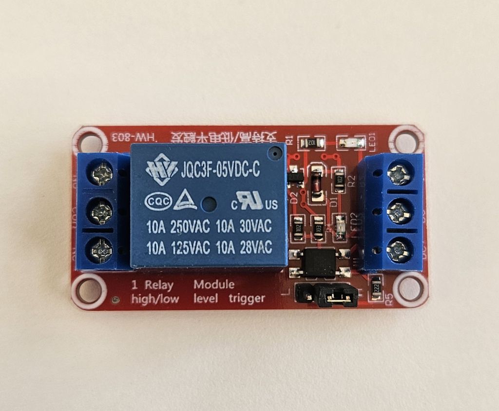
Relay Configuration
The wiring and operation of the backup relays are straightforward:
- Control Circuit: Driven by a direct 5V power supply and GND, with the trigger signals coming directly from two XIAO pins operating at 3.3V.
- Power Circuit: Sourced directly from the 24V power supply. The relays act as mechanical switches to interrupt or allow the current flow directly to the pump and the solenoid valve.
Once this electronic workaround was successfully implemented, the fabrication of the remaining boards was finalized, and the OLED display mount was 3D printed using PLA.
Week2 1 - 7
System Integration, Assembly & Functional Testing
- Timeline: June 1st – June 7th
- Objective: Mechanical and Electrical Assembly. Functional Testing
Following the setbacks with the relay driver stage, the timeline for the final project had to be restructured.
The initial plan was to complete the entire mechanical and electronic integration during the previous week, utilizing a planned vacation period from my regular job to maintain exclusive dedication to the project.
However, troubleshooting the hardware forced the assembly phase into this week, requiring a demanding balance between professional work commitments and intense hours at the Fab Lab, significantly restricting the overall time available.
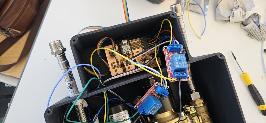
1. Mechanical Assembly and Structural Housing
The physical integration of the SmartFlow ACS system was executed to guarantee a compact, secure, and fully portable unit without requiring any residential masonry work. The assembly workflow consisted of the following stages:
- Main Electronics Housing: The 3D-printed enclosure (fabricated in PETG for improved thermal and mechanical resistance) was cleaned and prepared. Threaded inserts or precise mechanical fasteners were used to securely anchor the main PCB, preventing short circuits or physical stress on the solder joints.
- Hydraulic Block Integration: The water temperature probes were integrated inline with the recirculating electro-pump. To achieve this, thermal silicone (heat-resistant silicone) was used to bond the NTC probe PCB directly to the plastic body of the pump. This was the only location where the bypass temperature could be measured accurately without compromising electrical insulation.
- Cable Management: The pump and the solenoid valve were wired to the relays, which in turn were connected to the main electronic board. Concurrently, a multi-core cable hose was utilized to connect the remote control unit to the main PCB. At this stage, it is worth noting that the cable integration did not turn out as initially expected, since the footprint and clearance required to house the two additional relays within the main electronics enclosure had not been originally anticipated. Nevertheless, there was sufficient space to accommodate them safely without compromising the electrical insulation between components.
2. Electrical and Signal Integration
Once the physical components were placed, the wiring system was completed and double-checked:
- Isolation Check: Strict physical separation was maintained between the low-voltage DC logic (Seeed XIAO RP2040 control lines) and the 24V DC mains voltage handling the pump commutation through the revised relay drivers.
- Sensor Wiring: Temperature sensors (NTC) was connected to their dedicated pin headers, ensuring solid continuity and avoiding signal noise caused by loose connections.
3. Preliminary Functional Testing
With the system fully assembled, a series of controlled tests were initiated on the workbench before deploying the unit to a real test environment:
- Power-On Sequence: Safe powering of the logic board via USB/DC-DC converter, monitoring for any unexpected current draw or component heating.
- Sensor Telemetry Verification: Checking that the data stream for water temperature was correctly interpreted by the microcontroller.
- Actuator Triggering: Verifying that the newly corrected relay circuit safely switched the pump on and off according to the control algorithms without causing voltage spikes or microcontroller resets.
4. Remote Control Unit Assembly
The remote control enclosure was manufactured with precise tolerances so that the component-bearing PCB achieved a perfect press-fit alignment. This provided the exact depth required for the acrylic cover to sit flush with the OLED display surface.
The activation push-button was installed on the lateral side of the housing, securely anchored using its own structural hex nut.
5. Enclosure Sealing and Final Hardware Closure
Once all internal components were fully integrated, both the main base unit and the remote control housing were sealed. The top covers, which were laser-cut from acrylic sheet, were precisely aligned and fastened to the main bodies using mechanical screws, ensuring a solid and robust final finish.
.jpg)
6. Initial Functional Testing
Finally, during the weekend prior to the official presentation on June 8th, the entire system was thoroughly tested, verifying its optimal performance and successful operation.
FUNCTIONAL TESTING AND VALIDATION
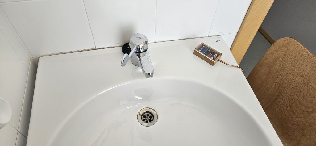
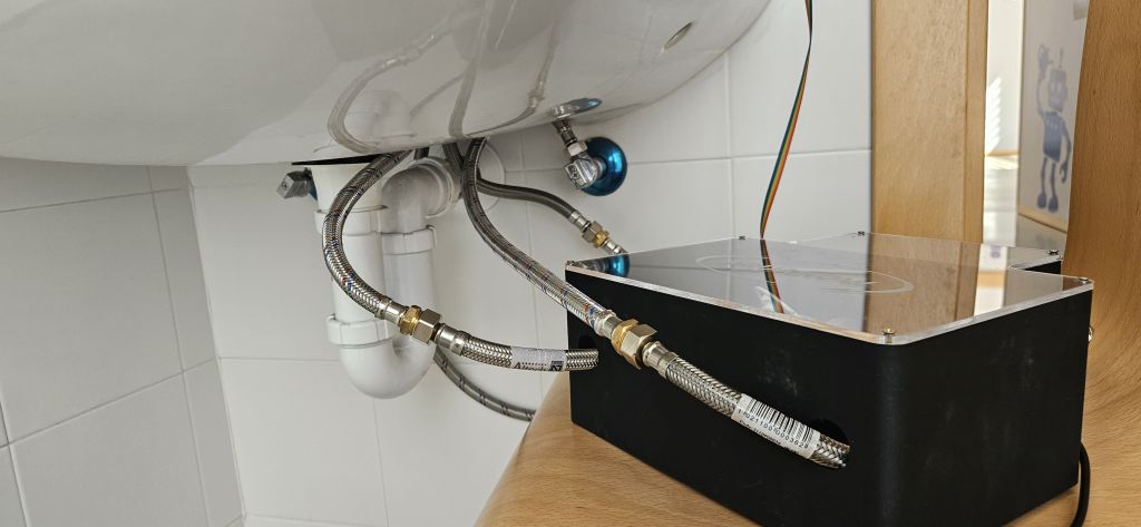
The system's hydraulic lines were connected to a Fab Lab water tap using flexible hoses, and the main power supply was energized.
Through this live setup, it was successfully verified that the entire integrated system operates safely and functions exactly as designed.
FUTURE WORK & SCALABILITY
To transition the SmartFlow ACS from a successful functional prototype to a commercial or highly optimized open-source product, several design iterations have been planned for future versions:
- Power Stage Redesign: The next hardware spin will feature dedicated driver ICs or solid-state components precisely matched to the inductive load and power requirements of the pump. This layout rewrite will completely isolate and eliminate the voltage spike vulnerabilities experienced in the initial stage.
- Wireless Connectivity Ecosystem: To eliminate the physical multi-core cable tethering the main unit to the user interface, the system will pivot to a wireless architecture. By incorporating Seeed XIAO ESP32 modules on both the main board and the remote control, the devices will communicate via ESP-NOW or Wi-Fi. This upgrade expands the installation range and drastically improves adaptability across a wider variety of residential sink layouts.
- Battery-Powered Remote Control: Transitioning to a wireless remote demands integrating an autonomous power system (such as LiPo cells or standard batteries). Consequently, the remote enclosure design must evolve to safely house both the power cells and recharging circuitry while maintaining a sleek, ergonomic, and compact profile.
- Form Factor Optimization: Thanks to the migration of power components to a streamlined PCB layout and the removal of bulky physical wiring, the footprint of the main base enclosure will be significantly downsized to achieve a minimalist, clutter-free installation.
ARDUINO CODE
Arduino Code for use with the Drivers
Drivers
// ====================================================================
//    SmartFlow ACS - Final Logic (NTC Probe Correction)
// ====================================================================

#include
#include
#include
#include  // Required for logarithmic calculation (NTC)

#define SCREEN_WIDTH 128
#define SCREEN_HEIGHT 64
#define OLED_RESET    -1
Adafruit_SSD1306 display(SCREEN_WIDTH, SCREEN_HEIGHT, &Wire, OLED_RESET);

// --- ORIGINAL PIN MAPPING ---
const int PIN_NTC = D0;
const int PIN_PUMP_IN1 = D1;
const int PIN_PUMP_IN2 = D2;
const int PIN_BUTTON = D3;
const int PIN_VALVE_IN1 = D6;
const int PIN_VALVE_IN2 = D7;

// --- NTC CONFIGURATION PARAMETERS ---
const float SERIES_RESISTANCE = 10000.0; // 10K fixed pull-up resistor
const float NOMINAL_THERMISTOR = 10000.0; // NTC resistance at 25°C (10K)
const float NOMINAL_TEMP = 25.0;         // Reference nominal temperature
const float BETA = 3950.0;               // Typical Beta coefficient for commercial NTCs
const int ADC_MAX = 1023;                // ADC Resolution (10-bit)

enum States { IDLE, TEMPORARY_SCREEN, RUNNING, COOL_DOWN_PHASE };
States currentState = IDLE;

unsigned long stateStartTime = 0;
unsigned long coolDownPhaseTime = 0;

void setup() {
  Serial.begin(115200);

  if(!display.begin(SSD1306_SWITCHCAPVCC, 0x3C)) {
    for(;;);
  }

  pinMode(PIN_PUMP_IN1, OUTPUT);
  pinMode(PIN_PUMP_IN2, OUTPUT);
  pinMode(PIN_VALVE_IN1, OUTPUT);
  pinMode(PIN_VALVE_IN2, OUTPUT);
  pinMode(PIN_BUTTON, INPUT);

  // Splash screen on boot
  display.clearDisplay();
  display.setTextColor(SSD1306_WHITE);
  display.setTextSize(1);
  display.setCursor(0, 10);
  display.println("  SYSTEM CONFIGURING");
  display.setCursor(0, 30);
  display.println("  Ready...");
  display.display();
  delay(2000);

  turnOffActuators();
}

void loop() {
  // 1. Read real temperature using the NTC thermistor equation
  int analogValue = analogRead(PIN_NTC);

  // Calculate NTC resistance based on ADC reading
  // (Adjusted for common voltage divider setup: NTC connected to GND and R_10K to VCC)
  float resistanceNTC = SERIES_RESISTANCE / ((float)ADC_MAX / analogValue - 1.0);

  // Apply Steinhart-Hart equation (Beta parameter equation)
  float temp;
  temp = resistanceNTC / NOMINAL_THERMISTOR;     // (R/Ro)
  temp = log(temp);                             // ln(R/Ro)
  temp /= BETA;                                 // 1/B * ln(R/Ro)
  temp += 1.0 / (NOMINAL_TEMP + 273.15);        // + (1/To)
  temp = 1.0 / temp;                            // Invert to obtain Kelvin
  temp -= 273.15;                               // Convert to Celsius

  // *Safety Note*: If the logic reads inverted, it means that on your PCB layout
  // the NTC is tied to VCC. In that case, change the 'resistanceNTC' calculation line to:
  // float resistanceNTC = SERIES_RESISTANCE * ((float)ADC_MAX / analogValue - 1.0);

  // 2. Detect actual button press (Falling Edge: transitions from HIGH to LOW)
  bool buttonPressed = false;
  if (digitalRead(PIN_BUTTON) == LOW) {
    delay(50); // Software debouncing filter to ignore initial hardware noise
    if (digitalRead(PIN_BUTTON) == LOW) {
      buttonPressed = true;

      // HANDBRAKE LOCK: Block code execution here until the button is fully RELEASED
      while(digitalRead(PIN_BUTTON) == LOW) {
        delay(10);
      }
    }
  }

  // 3. State Machine
  switch (currentState) {

    case IDLE:
      turnOffActuators();
      display.clearDisplay();
      display.display(); // Blank display for power saving mode

      if (buttonPressed) {
        stateStartTime = millis();
        if (temp > 30.0) {
          currentState = TEMPORARY_SCREEN;
        } else {
          currentState = RUNNING;
          stateStartTime = millis(); // Record timestamp when operation started (for the 5-min timeout)
        }
      }
      break;

    case TEMPORARY_SCREEN:
      updateOLED("HIGH TEMP", temp, "STANDBY");
      // Timeout after 5 seconds to turn off the display automatically
      if (millis() - stateStartTime >= 5000) {
        currentState = IDLE;
      }
      break;

    case RUNNING:
      turnOnActuators();
      updateOLED("RUNNING", temp, "PUMP:ON/VALV:ON");

      // Stop system if: Temp exceeds 35°C, 5 minutes pass (300,000 ms), or the button is pressed again
      if (temp >= 35.0 || (millis() - stateStartTime >= 300000) || buttonPressed) {
        currentState = COOL_DOWN_PHASE;
        coolDownPhaseTime = millis();
      }
      break;

    case COOL_DOWN_PHASE:
      unsigned long elapsedTime = millis() - coolDownPhaseTime;

      if (elapsedTime < 5000) {
        // First 5 seconds: Pump OFF, Solenoid Valve remains ON
        digitalWrite(PIN_PUMP_IN1, LOW);
        digitalWrite(PIN_PUMP_IN2, LOW);
        digitalWrite(PIN_VALVE_IN1, HIGH);
        digitalWrite(PIN_VALVE_IN2, LOW);
        updateOLED("PUMP OFF", temp, "PUMP:OFF/VALV:ON");
      }
      else if (elapsedTime >= 5000 && elapsedTime < 10000) {
        // From second 5 to 10: All Actuators OFF
        turnOffActuators();
        updateOLED("ALL OFF", temp, "PUMP:OFF/VALV:OFF");
      }
      else {
        // At 10 seconds, return to full standby mode and blank the screen
        currentState = IDLE;
      }
      break;
  }
  delay(20);
}

void turnOnActuators() {
  digitalWrite(PIN_PUMP_IN1, HIGH);
  digitalWrite(PIN_PUMP_IN2, LOW);
  digitalWrite(PIN_VALVE_IN1, HIGH);
  digitalWrite(PIN_VALVE_IN2, LOW);
}

void turnOffActuators() {
  digitalWrite(PIN_PUMP_IN1, LOW);
  digitalWrite(PIN_PUMP_IN2, LOW);
  digitalWrite(PIN_VALVE_IN1, LOW);
  digitalWrite(PIN_VALVE_IN2, LOW);
}

void updateOLED(String state, float temperature, String actuators) {
  display.clearDisplay();
  display.setTextColor(SSD1306_WHITE);
  display.setTextSize(1);
  display.setCursor(0, 0);  display.print("SMARTFLOW ACS");
  display.setCursor(0, 12); display.print("ST: "); display.print(state);
  display.setTextSize(2);
  display.setCursor(0, 26); display.print(temperature, 1); display.write(247); display.print("C");
  display.setTextSize(1);
  display.setCursor(0, 52); display.print("OUT: "); display.print(actuators);
  display.display();
}
Arduino Code for use with the Relays
Relays
// ====================================================================
//    SmartFlow ACS - Production Logic with Relays (Final NTC)
//    v3.2 - Temperature updated every 1 second
// ====================================================================

#include
#include
#include
#include  // Required for logarithmic calculation (NTC)

#define SCREEN_WIDTH 128
#define SCREEN_HEIGHT 64
#define OLED_RESET    -1
Adafruit_SSD1306 display(SCREEN_WIDTH, SCREEN_HEIGHT, &Wire, OLED_RESET);

// --- FINAL PIN MAPPING WITH RELAYS ---
const int PIN_NTC = D0;          // Thermistor analog input
const int PIN_BUTTON = D3;       // Physical push-button on D3
const int PIN_PUMP_RELAY = D8;   // Output for Pump relay
const int PIN_VALVE_RELAY = D9;  // Output for Solenoid Valve relay

// --- NTC CONFIGURATION PARAMETERS ---
const float SERIES_RESISTANCE = 10000.0; // 10K fixed pull-up resistor
const float NOMINAL_THERMISTOR = 10000.0; // NTC resistance at 25°C (10K)
const float NOMINAL_TEMP = 25.0;         // Reference nominal temperature
const float BETA = 3950.0;               // Typical Beta coefficient for commercial NTCs
const int ADC_MAX = 1023;                // ADC Resolution (10-bit)

// --- DIRECT LOGIC CONFIGURATION ---
const int RELAY_ON = HIGH;  // HIGH activates the external relay
const int RELAY_OFF = LOW;  // LOW deactivates it

enum States { IDLE, TEMPORARY_SCREEN, RUNNING, COOL_DOWN_PHASE };
States currentState = IDLE;

unsigned long stateStartTime = 0;
unsigned long coolDownPhaseTime = 0;

// --- VARIABLES FOR TEMPERATURE STABILIZATION ---
unsigned long lastTempSampling = 0;    // Stores when the last measurement occurred
float stableTemp = 20.0;               // Stores the last calculated value to use in the loop

void setup() {
  Serial.begin(115200);

  if(!display.begin(SSD1306_SWITCHCAPVCC, 0x3C)) {
    for(;;);
  }

  // Configure relay pins as outputs
  pinMode(PIN_PUMP_RELAY, OUTPUT);
  pinMode(PIN_VALVE_RELAY, OUTPUT);
  pinMode(PIN_BUTTON, INPUT);

  // For safety, ensure they initialize turned off
  turnOffActuators();

  // Splash screen on boot
  display.clearDisplay();
  display.setTextColor(SSD1306_WHITE);
  display.setTextSize(1);
  display.setCursor(0, 10);
  display.println("  SMARTFLOW ACS v3.2");
  display.setCursor(0, 30);
  display.println("  Stabilized Temp.");
  display.display();
  delay(2000);

  // Perform an initial reading so it does not default to 20.0ºC
  readTemperature();
}

void loop() {
  // 1. Sample temperature only every 1000 milliseconds (1 second)
  if (millis() - lastTempSampling >= 1000) {
    readTemperature();
    lastTempSampling = millis(); // Reset the sample interval timer
  }

  // 2. Detect actual button press with edge control (waits for release)
  bool buttonPressed = false;
  if (digitalRead(PIN_BUTTON) == LOW) {
    delay(50); // Software debouncing filter
    if (digitalRead(PIN_BUTTON) == LOW) {
      buttonPressed = true;
      while(digitalRead(PIN_BUTTON) == LOW) {
        delay(10); // Block execution until the button is fully released
      }
    }
  }

  // 3. State Machine utilizing the stabilized temperature value
  switch (currentState) {

    case IDLE:
      turnOffActuators();
      display.clearDisplay();
      display.display(); // Blank screen (Power saving mode)

      if (buttonPressed) {
        stateStartTime = millis();
        if (stableTemp > 30.0) {
          currentState = TEMPORARY_SCREEN;
        } else {
          currentState = RUNNING;
          stateStartTime = millis(); // Record timestamp when operation started
        }
      }
      break;

    case TEMPORARY_SCREEN:
      updateOLED("HIGH TEMP", stableTemp, "STANDBY");
      if (millis() - stateStartTime >= 5000) {
        currentState = IDLE;
      }
      break;

    case RUNNING:
      turnOnActuators();
      updateOLED("RUNNING", stableTemp, "PUMP:ON/VALV:ON");

      // Stop conditions utilizing the stable temperature value
      if (stableTemp >= 35.0 || (millis() - stateStartTime >= 300000) || buttonPressed) {
        currentState = COOL_DOWN_PHASE;
        coolDownPhaseTime = millis();
      }
      break;

    case COOL_DOWN_PHASE:
      unsigned long elapsedTime = millis() - coolDownPhaseTime;

      if (elapsedTime < 5000) {
        digitalWrite(PIN_PUMP_RELAY, RELAY_OFF);
        digitalWrite(PIN_VALVE_RELAY, RELAY_ON);
        updateOLED("PUMP OFF", stableTemp, "PUMP:OFF/VALV:ON");
      }
      else if (elapsedTime >= 5000 && elapsedTime < 10000) {
        digitalWrite(PIN_PUMP_RELAY, RELAY_OFF);
        digitalWrite(PIN_VALVE_RELAY, RELAY_OFF);
        updateOLED("ALL OFF", stableTemp, "PUMP:OFF/VALV:OFF");
      }
      else {
        currentState = IDLE;
      }
      break;
  }
  delay(20);
}

// --- SEPARATED FUNCTION TO READ THE NTC THERMISTOR ---
void readTemperature() {
  int analogValue = analogRead(PIN_NTC);
  float resistanceNTC = SERIES_RESISTANCE / ((float)ADC_MAX / analogValue - 1.0);

  float temp;
  temp = resistanceNTC / NOMINAL_THERMISTOR;
  temp = log(temp);
  temp /= BETA;
  temp += 1.0 / (NOMINAL_TEMP + 273.15);
  temp = 1.0 / temp;
  temp -= 273.15;

  stableTemp = temp; // Update the global variable read by the rest of the program
}

// --- ACTUATOR CONTROL FUNCTIONS ---
void turnOnActuators() {
  digitalWrite(PIN_PUMP_RELAY, RELAY_ON);
  digitalWrite(PIN_VALVE_RELAY, RELAY_ON);
}

void turnOffActuators() {
  digitalWrite(PIN_PUMP_RELAY, RELAY_OFF);
  digitalWrite(PIN_VALVE_RELAY, RELAY_OFF);
}

void updateOLED(String state, float temperature, String actuators) {
  display.clearDisplay();
  display.setTextColor(SSD1306_WHITE);
  display.setTextSize(1);
  display.setCursor(0, 0);  display.print("SMARTFLOW ACS");
  display.setCursor(0, 12); display.print("ST: "); display.print(state);
  display.setTextSize(2);
  display.setCursor(0, 26); display.print(temperature, 1); display.write(247); display.print("C");
  display.setTextSize(1);
  display.setCursor(0, 52); display.print("OUT: "); display.print(actuators);
  display.display();
}
AI Code Disclosure
Generative AI tools were utilized to optimize the core state machine architecture and robust button debouncing control structure.
Prompt used for the main state machine logic:
Act as an embedded systems developer expert in Arduino. Design a non-blocking state machine for an RP2040.
The system controls a water recirculation loop with a pump and a solenoid valve. It must have 4 states:
IDLE (blank screen), TEMPORARY_SCREEN (shows alert if water is already hot), RUNNING (actuators on, stops if temp >= 35°C, button pressed, or 5 min timeout), and a sequential COOL_DOWN_PHASE (turns off pump first for 5s while valve stays open to prevent water hammer, then shuts down everything after another 5s).
Include a robust hardware button debouncing logic that blocks execution only during the release phase.
AI Collaboration & Code Generation Insights
To obtain the Arduino code shared above, I collaborated with AI, specifically using Gemini. However, there is no single, specific prompt used to generate the code. Instead, the process relies on an ongoing, natural dialogue where I explain the logical ideas and specific tasks I want the microcontroller to execute.
Furthermore, with the memory and past activity features enabled, Gemini retains the context of previous project developments and adapts to my workflow preferences. As a result, the AI often anticipates my technical requirements, occasionally proposing relevant code structures even before they are explicitly requested.