WEEK 16 SYSTEM INTEGRATION
- INTRODUCTION
- SCHEMATIC & SYSTEM OVERVIEW
- DESIGN
- SYSTEM LOGIC & OPERATION
- RENDERING & VISUALIZATION
- PROJECT MANAGEMENT & TIMELINE
- INVENTORY & BILL OF MATERIALS (BOM)
INTRODUCTION
The Problem
In most households, a significant amount of water is wasted while waiting for it to reach the desired temperature.
When the hot water tap is turned on, liters of cold water, already sitting in the pipes, flow directly down the drain before the heated water finally arrives.
This inefficiency results in both resource waste and unnecessary wait times.
The Solution
My project addresses this issue by implementing a water recirculation and pre-heating system.
The goal is to circulate water through the pipes to prime them while the tap remains closed. By the time the user opens the faucet, hot water is delivered instantaneously, preventing the waste of treated water and optimizing domestic energy use.
SCHEMATIC & SYSTEM OVERVIEW
In a standard residential setting, the plumbing installation typically follows the layout shown in the schematic below:
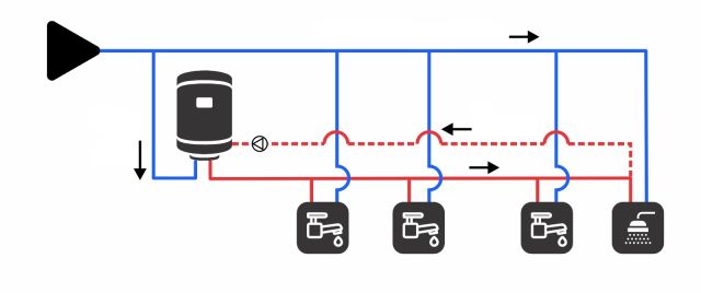
The dashed red line represents a 'site-built' recirculation system, which solves the described problem but requires a dedicated return line that cannot be easily installed in existing homes.
My system is designed to solve this issue, allowing for a retrofit installation in any finished housing without the need for major structural changes.
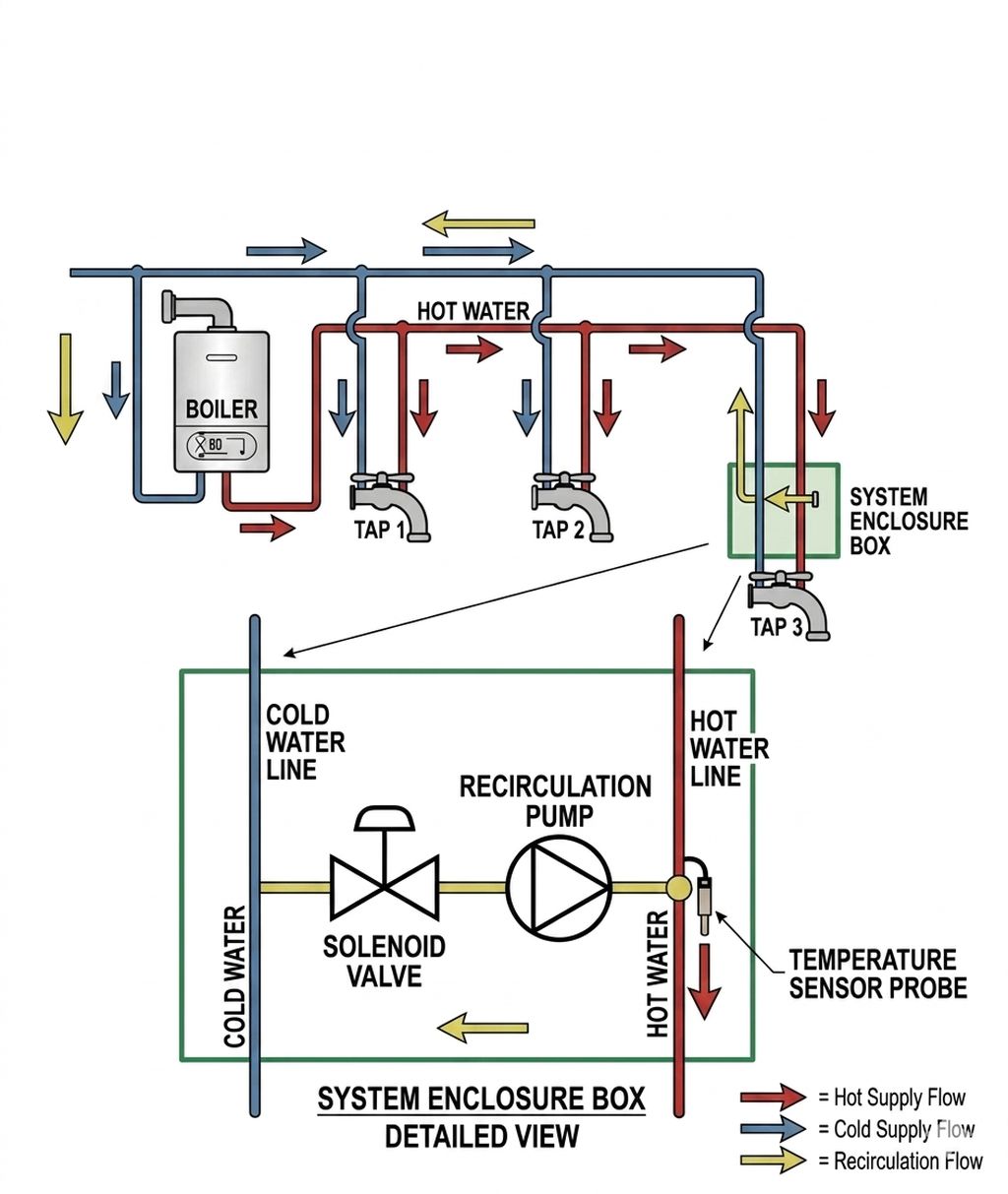
System Integration
My system is designed to be installed at one of the faucet nodes, enabling water recirculation through the existing cold water lines. This configuration allows the system to bypass the traditional drainage route, as illustrated in the following schematic:
DESIGN
The design is comprised of straightforward components, organized into two distinct subsystems:
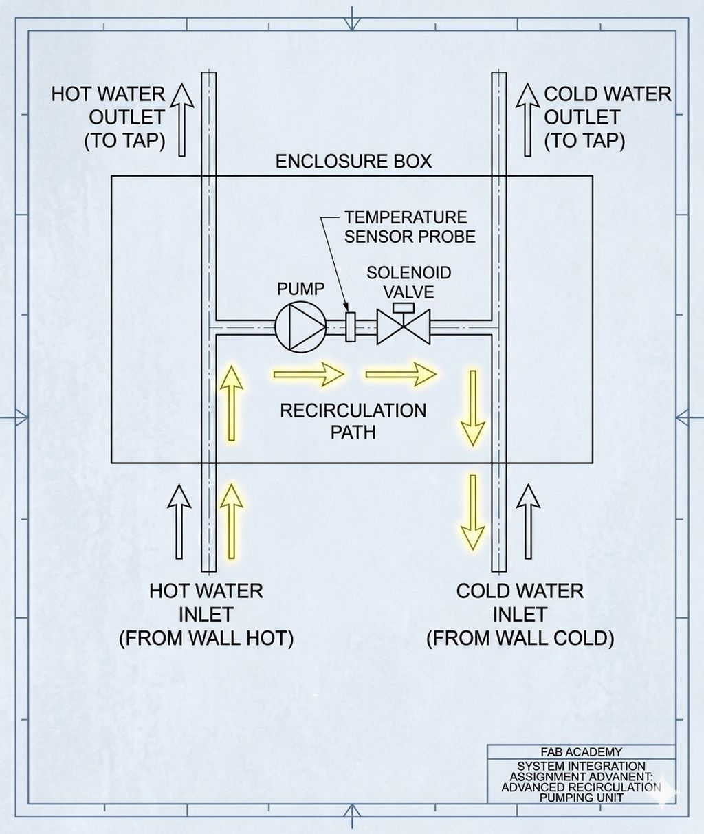
Plumbing & Hydraulics
The hydraulic system relies on two primary components:
- Water Pump: Responsible for driving the water recirculation through the circuit.
- Solenoid Valve: Acts as the primary control gate. Its function is to close the connection between the hot and cold water lines when the system is in standby mode, preventing backflow or unintended mixing.
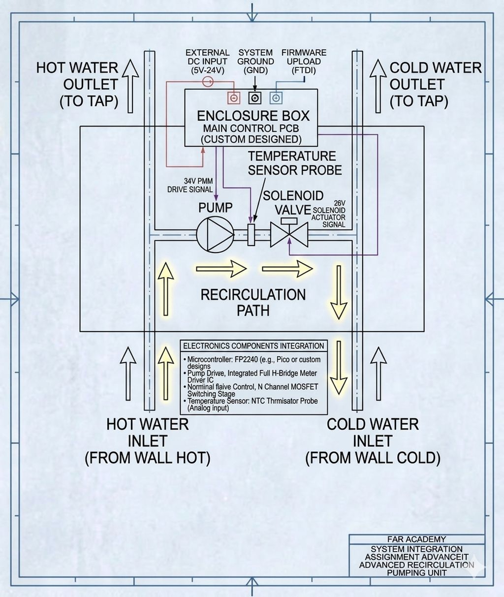
Electronics & Power Supply
The electrical subsystem is composed of the following core elements:
- Power Supply Unit (Transformer): A dual-voltage setup designed to power the control electronics at 5V and provide 24V for the pump and solenoid valve.
- Control Board: A custom PCB (or development board) featuring the RP2040 microcontroller, which manages the system logic and I/O.
- Temperature Probe: A dedicated sensor integrated into the hydraulic circuit to monitor the temperature of the recirculating water in real-time.
The temperature probe is strategically positioned between the pump and the solenoid valve for optimal thermal reading.
SYSTEM LOGIC & OPERATION
The system operates under a straightforward yet precise logic, which is detailed in the functional block diagram below:
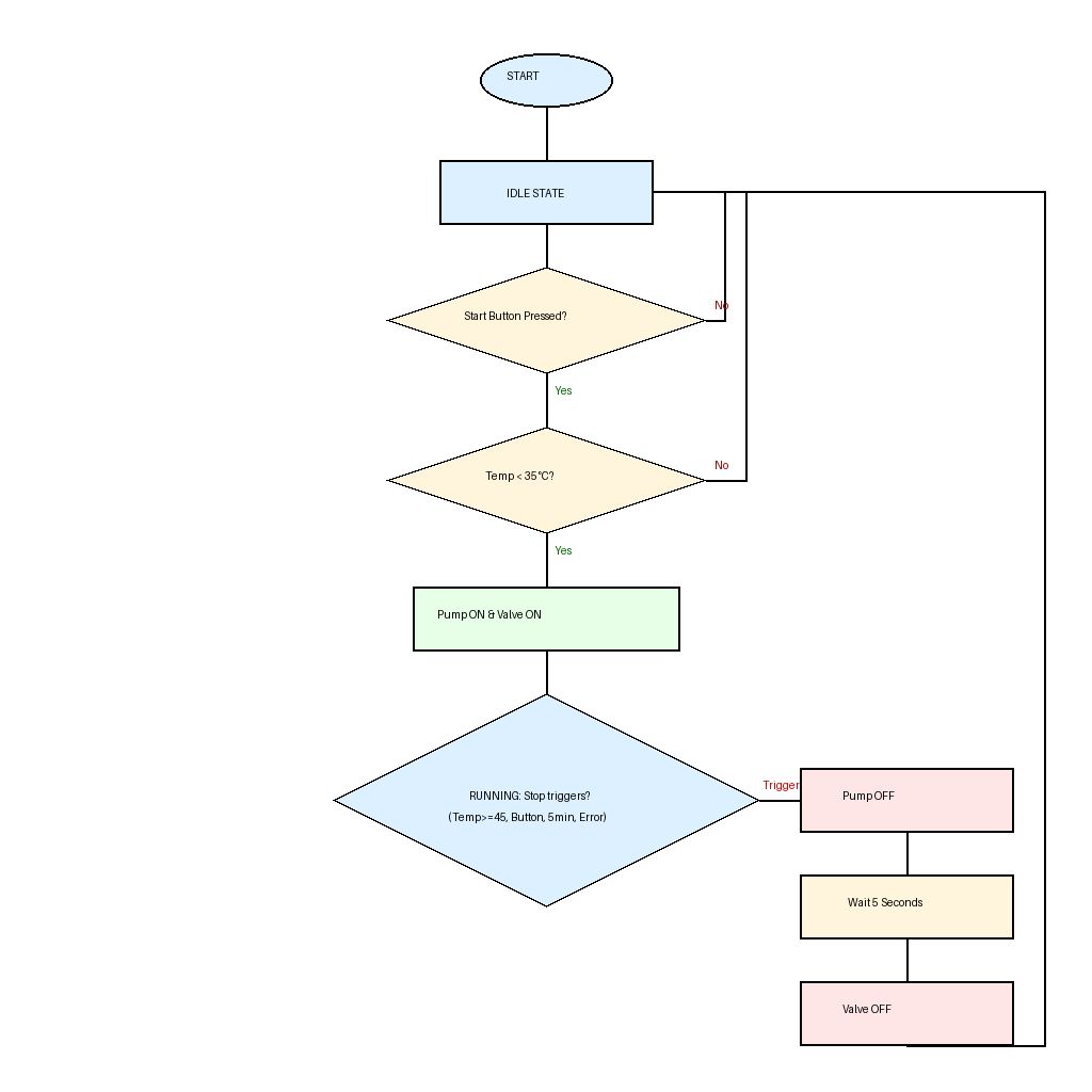
Sequence Description
- IDLE State (Standby)
- Condition: System is OFF
- Trigger: Start button is pressed AND Temperature is below 35°C
- Action: Pump and Valve are energized simultaneously. Transition to RUNNING state
- RUNNING State (Active Operation)
- Monitoring: The system continuously polls the temperature sensor and internal timer
- Exit Conditions:
- Temperature reaches >= 45°C (Overheat protection/Target reached)
- Start/Stop button is pressed again (Manual override)
- Time elapsed exceeds 5 minutes (Safety timeout)
- Action: Transition to SHUTDOWN state
- SHUTDOWN State (Sequential Stop)
- Step A: The Pump is turned OFF immediately to stop fluid flow
- Step B: A non-blocking timer starts for a 5-second delay (to depressurize or clear the line)
- Step C: The Valve is turned OFF
- Final Action: System returns to IDLE state, ready for the next cycle
RENDERING & VISUALIZATION
The following AI-generated image illustrates the final assembly, showcasing the full integration of the hydraulic and electronic subsystems into a functional prototype:
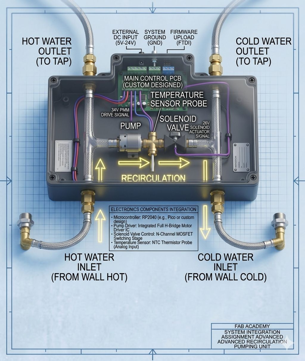
Conceptual render of the integrated system, featuring the RP2040 control unit, the 24V power stage, and the recirculating hydraulic circuit.
PROJECT MANAGEMENT & TIMELINE
To be honest, this assignment has been the most challenging so far, as defining the starting point was a complex task.
The requirement is to establish a working plan for the Final Project, and considering my current time constraints, I have dedicated a single week of vacation to develop the entire workflow.
My primary milestones for this intensive week are:
- Electronics Design & Production: Designing the custom PCB and completing the fabrication process.
- Enclosure Design & 3D Printing: Designing and manufacturing the housing for the integrated system.
- Hydraulic Assembly: Integrating the plumbing components into the main enclosure.
- Wiring & System Testing: Completing the electrical connections and performing functional tests.
Current Challenges:
As of today, the selection of materials for the electronics housing and the specific mounting mechanisms are still under evaluation. This uncertainty is part of the iterative design process I am currently navigating.
Considering the upcoming tasks and the limited time available, I have developed the following schedule to guide my progress. I am committed to meeting these deadlines:
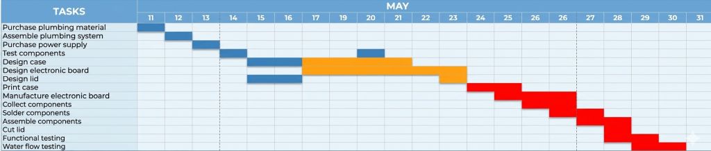
As shown in the timeline, I have not scheduled any tasks for June. I am reserving this period as a buffer to account for potential delays and to allow for any necessary schedule adjustments.
INVENTORY & BILL OF MATERIALS (BOM)
The most significant expense lies in acquiring the components for the hydraulic section:
- Recirculation Pump: €30.49
- Solenoid Valve: €29.99
- Plumbing supplies: €19.35
The remaining components, electronics, and fabrication materials are significantly cheaper:
- Seeed Studio XIAO RP2040: €4.99
- NTC Thermistor (10kΩ, 3750K, 1206 package): €0.09
- CONN PWR Jack 2.5X5.5MM Solder: €0.83
- Driver Toshiba TB67H451FNG,EL: €1.14 x 2
- Regulator LM2940IMPX-5.0/NOPB: €1.61
- 0.96 Inch OLED Display Module SSD1306 I2C: €0.92
- Button PBS-110 NO: €0.40
- Manufacturing materials: €10
The cost of the PETG filament used for the 10-hour 3D print, combined with the acrylic, wood, and minor electronic components, is well under €10 (roughly €7 in total).
Therefore, the final product cost comes to approximately €100.95.