Week 14
Moulding and Casting
Contents
Starting Point
As a starting point, my previous experience with these types of processes is quite limited. I have worked occasionally with resins and fiberglass mat, mainly for repairing and reinforcing motorcycle fairings. Although this is not directly related to moulding and casting, it provided a first contact with composite materials, mixing processes, and curing times, which serves as a useful foundation for this week.
Group assignment
We have decided that, as a group effort, each of us will specifically document some of the tests performed on our page.
Review the safety data sheets for each of your moulding and casting materials.
Moulding materials
Ferris File-A-Wax Blue
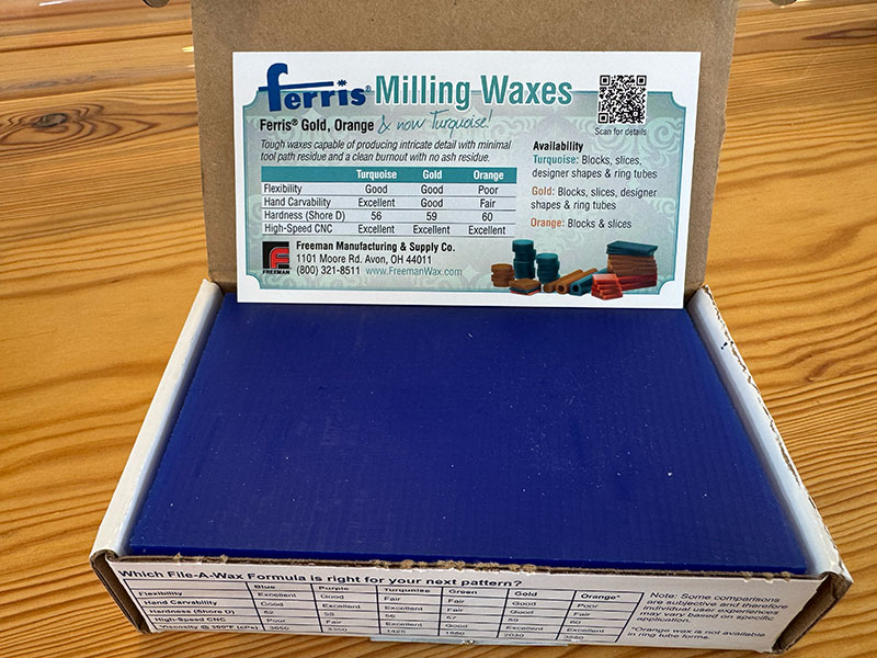
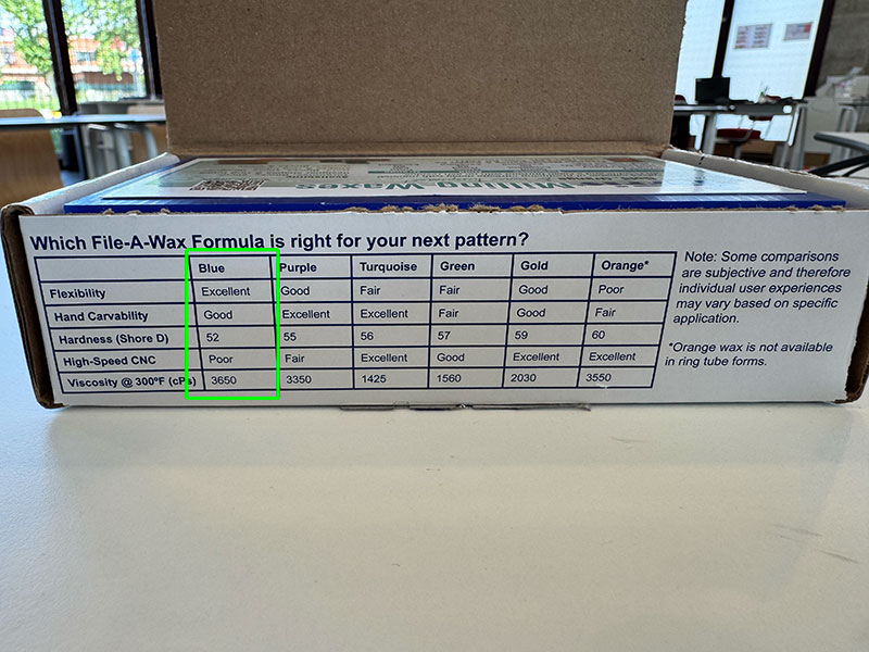
Ferris File-A-Wax Blue is a high-quality solid wax designed for carving and machining processes, especially in prototyping and jewelry applications. It offers good hand workability, balanced rigidity, and a very low residue content, which helps achieve clean and precise finishes. It is also a stable and safe material under normal use conditions, with a relatively low melting point that makes it suitable for moulding and casting processes.
Main characteristics
| Property | Value / Description |
|---|---|
| Material | Polyethylene-based wax with additives and dye |
| Color | Blue |
| Physical state | Solid at room temperature |
| Melting point | ~104–115 °C |
| Density | ~0.9–0.92 g/cm³ |
| Hardness (Shore D) | ~52 |
| Flexibility | Excellent |
| Hand carving | Good |
| CNC machining | Moderate (not optimal for high-speed machining) |
| Water solubility | Negligible |
| Ash content | ~0.003% (very low residue) |
Safety
| Aspect | Details |
|---|---|
| Hazard classification | Not classified as hazardous |
| Main risk | Burns from molten material |
| Flammability | Not flammable under normal conditions |
| Fire hazard | Dust in air may create explosion risk (rare in normal use) |
| Handling | Avoid contact with molten wax, use in ventilated areas |
| Personal protection | Safety glasses and heat-resistant gloves when hot |
| Storage | Keep away from heat, flames, and strong oxidizers |
| Toxicity | Low toxicity, not carcinogenic under normal use |
Datasheet
- Technical data sheet (01Wax_tds-faw.pdf) PDF · 112 Kb
- Safety data sheet (01Wax_sds-fawblue.pdf) PDF · 156 Kb
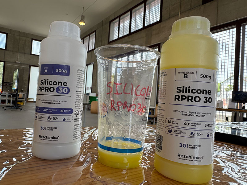
Reschimica R PRO 30 - Silicone rubber mould making
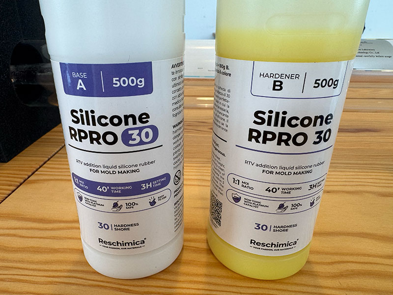
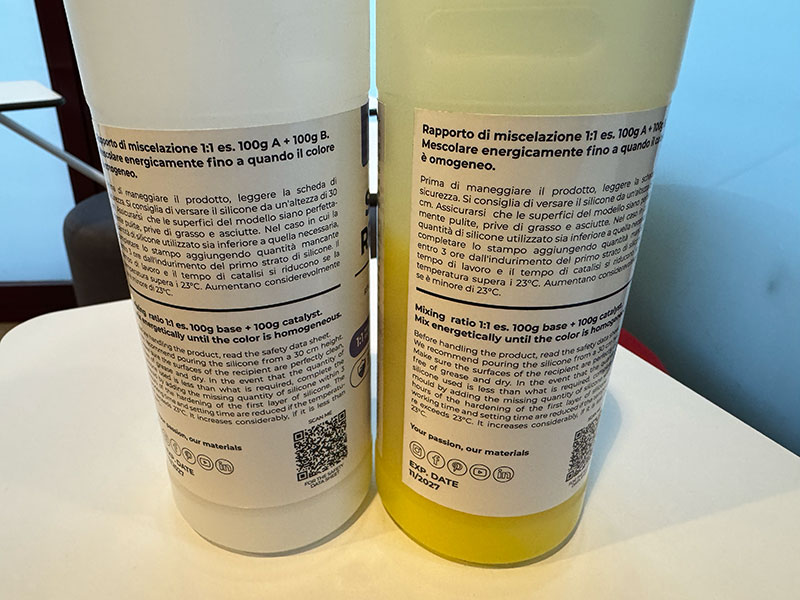
RESCHIMICA R PRO 30 is a two-component silicone rubber system (base + catalyst) designed for mould making. It is a liquid silicone-based blend that, after curing, becomes a flexible and stable material capable of reproducing fine details with high accuracy. According to its datasheet, it is not classified as hazardous under normal conditions of use and handling, making it suitable for workshop and prototyping processes.
Main features
| Feature | Component A (Base) | Component B (Catalyst) |
|---|---|---|
| Type | Silicone-based liquid | Silicone-based liquid (curing agent) |
| Function | Main material body | Initiates curing reaction |
| Appearance | Liquid, odourless | Liquid, odourless |
| Density (20ºC) | ~1.10 g/cm³ | ~1.24 g/cm³ |
| Viscosity (20ºC) | ~7.69 mPa·s | ~7.69 mPa·s |
| Boiling point | ~175ºC | ~175ºC |
| Flash point | Non-flammable (>60ºC) | Non-flammable (>60ºC) |
| Mix ratio | 1:1 | |
| Working time | 40 min | |
| Setting time | 3 h | |
| Demoulding time | ~12–24 h | |
| Full curing time | ~24 h | |
| Stability | Chemically stable under normal conditions | Chemically stable under normal conditions |
| Storage temperature | 5ºC – 30ºC | 5ºC – 30ºC |
| Shelf life | Up to 6 months | Up to 6 months |
| Final result | Flexible silicone rubber with high detail reproduction | |
Safety information – RESCHIMICA R PRO 30
| Safety aspect | Description |
|---|---|
| Hazard classification | Not classified as hazardous under normal use conditions |
| Inhalation risk | No significant risk expected in normal conditions |
| Skin contact | Wash with water and neutral soap if contact occurs |
| Eye contact | Rinse with water for at least 15 minutes and seek medical advice |
| Ingestion | Seek immediate medical assistance |
| Fire behaviour | Non-flammable under normal conditions |
| Protective equipment | Basic PPE recommended (gloves, eye protection) |
| Environmental precautions | Avoid release into drains or environment |
| Handling recommendations | Work in clean, ventilated area and avoid contamination |
| Storage conditions | Keep away from heat, ignition sources, and food |
Datasheet
- Data sheet ENGLISH (01Silicone_r-pro-30ENG.pdf) PDF · 286 Kb
- Data sheet SPANISH (01Silicone_r-pro-30SP.pdf) PDF · 294 Kb
Casting
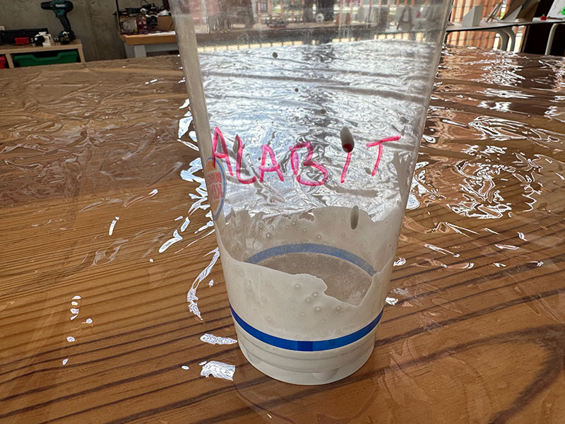
Alabit modelling plaster
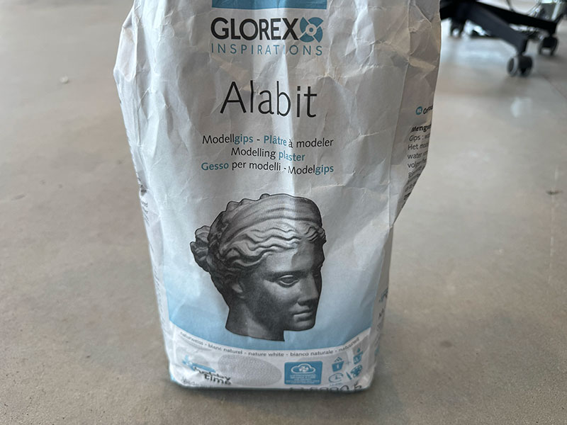
Alabit is a white, high-quality modelling plaster which is used for small reliefs, models and also for making moulds. Mixing ratio: water = 1 : 0,7.
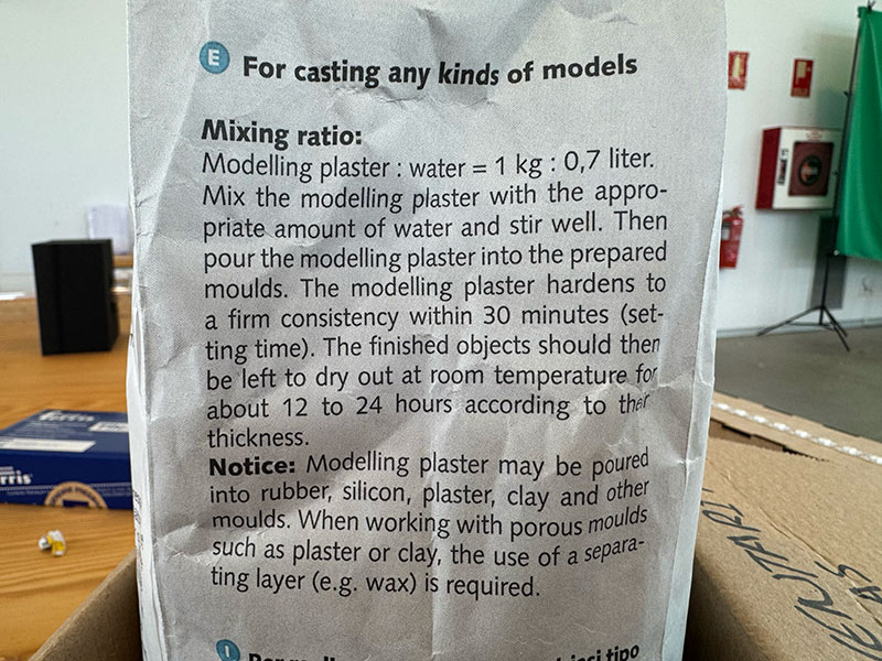
Mixing ratio:
Modelling plaster : water = 1 kg : 0.7 liter.
Mix the modelling plaster with the appropriate amount of water and stir well. Then pour the modelling plaster into the prepared moulds. The modelling plaster hardens to a firm consistency within 30 minutes (setting time). The finished objects should then be left to dry out at room temperature for about 12 to 24 hours, according to their thickness.
Notice: Modelling plaster may be poured into rubber, silicon, plaster, clay and other moulds. When working with porous moulds such as plaster or clay, the use of a separating layer, e.g. wax, is required.
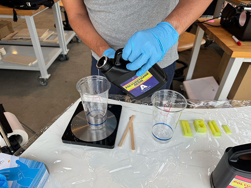
DecorRom two-part Polyurethane Resin

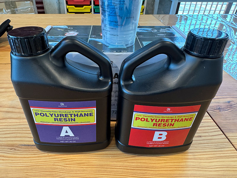
The DecorRom Polyurethane Resin 72oz is a two-part polyurethane resin designed for fast casting processes and for producing detailed parts. It stands out for its 1:1 mixing ratio, its very fast curing time, and its low viscosity, which helps the resin flow easily into complex molds and capture fine details.
Once cured, it produces a solid white material with good hardness and stability, making it suitable for prototypes, sculptures, figurines, and modeling applications. Its low-odor formulation makes it more comfortable to use, although it is still important to work quickly because of its short working time and to avoid moisture during the casting process.
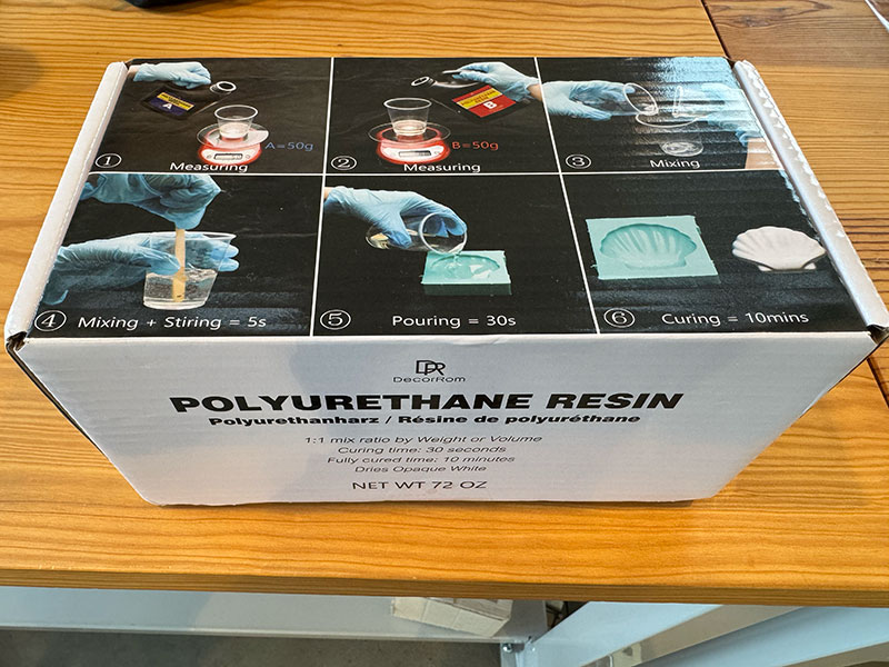
DecorRom Polyurethane Resin - Technical Specifications
| Property | Specification |
|---|---|
| Material type | Two-part polyurethane casting resin |
| Mixing ratio | 1:1, Part A and Part B |
| Working time | Approximately 20-30 seconds |
| Stirring time | Approximately 5 seconds |
| Demoulding time | Approximately 10 minutes |
| Final color | Opaque white |
| Hardness | 95D |
| Viscosity | Low viscosity, suitable for detailed molds |
| Odor | Low odor formulation |
| Shrinkage | Minimal shrinkage |
| Heat resistance | Up to 200°F / approximately 93°C |
| Post-processing | Machinable and paintable after full curing |
| Recommended applications | Prototype models, sculptures, figurines, props, decorative pieces and small craft projects |
| Package size | 72 oz / approximately 2000 g |
Safety Considerations
| Safety aspect | Recommendation |
|---|---|
| Personal protection | Wear protective gloves, safety glasses and a face mask during handling and casting. |
| Ventilation | Work in a well-ventilated area, even though the resin is described as low odor. |
| Skin contact | Avoid direct contact with uncured resin. Wash immediately with soap and water if contact occurs. |
| Eye contact | Avoid splashes. In case of contact, rinse carefully with water and seek medical advice if irritation continues. |
| Inhalation | Avoid breathing vapors. Use a mask and ensure good airflow, especially when working indoors. |
| Working time risk | The resin cures very quickly, so all tools, molds and materials should be prepared before mixing. |
| Heat generation | Avoid large castings, as rapid curing may generate heat and cause distortion. |
| Moisture sensitivity | Keep containers tightly closed and avoid moisture contamination, which can affect the curing process. |
| Storage | Store in a cool, dry place away from direct sunlight and use soon after opening. |
| Food contact | Do not use for food-safe applications unless a specific certified datasheet confirms it. |
| Disposal | Dispose of uncured resin and contaminated materials according to local chemical waste regulations. |
Note: This product does not provide a complete official technical datasheet. The values presented above are based on manufacturer descriptions and practical observations during the casting process. Therefore, they should be considered as approximate reference values rather than standardized material properties.
Make and compare test casts with each of them.
Reschimica R PRO 30 - Silicone rubber
Alabit modelling plaster
DecorRom Polyurethane Resin
Compare printing vs milling molds.
See complete processes below:
Individual assignment
Design a mold around the process you'll be using, produce it with a smooth surface finish that does not show the production process toolpath, and use it to cast parts..
3D mold design
For the 3D mold design, I used FreeCAD, following a similar workflow to previous weeks.
I decided to start with a simple approach, designing a single-part mold that would allow me to validate the process before moving on to more complex geometries. The design consists of a semicircular shape combined with half of a cylinder, to which I later added the FabLab imagotype as a raised feature.
The process began by creating a base cube, from which I performed several subtraction operations. Specifically, I removed the volume of two additional cubes to generate an internal cavity, necessary to facilitate the demolding process.
Next, I modeled the semicircle and the cylinder, positioning them along the central axis of the inner base of the mold. Once properly aligned, I applied a fusion operation, combining both geometries into a single solid.
As a final design step, I imported the FabLab imagotype in .svg format. From this file, I created a sketch based on the vector paths and then applied an extrusion, generating the logo relief on the mold surface.
Finally, the complete model was exported as an .stl file, ready for fabrication.
High quality video available on my YouTube channel ↗️.
Miling 3D mold
For the mold fabrication, the first step was to prepare a wax block, securing it properly on the milling machine to ensure stability throughout the process.
The machining strategy was divided into two main stages: roughing and finishing. This combination allows, on one hand, to efficiently remove large amounts of material, and on the other, to achieve a better surface quality and finer details in the final geometry.
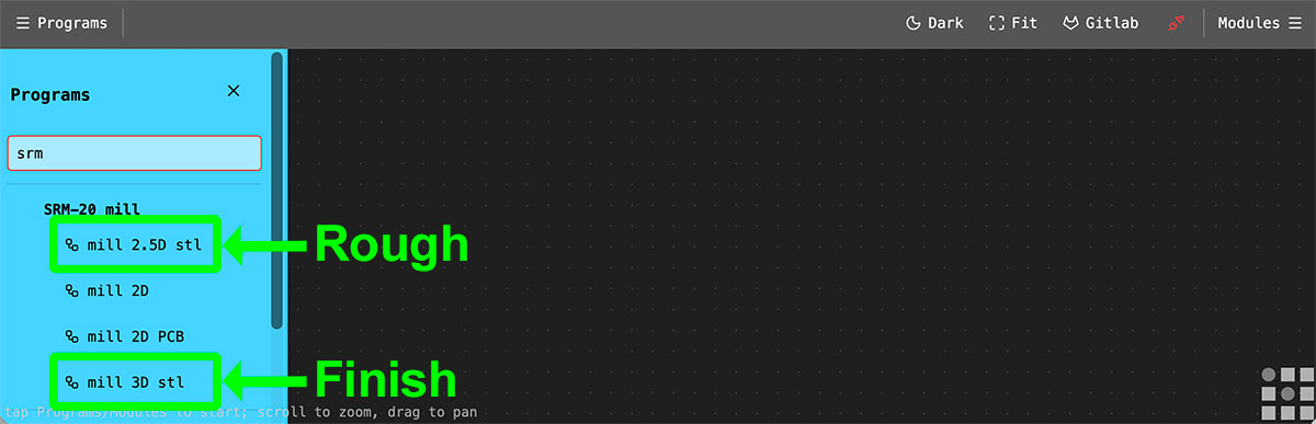
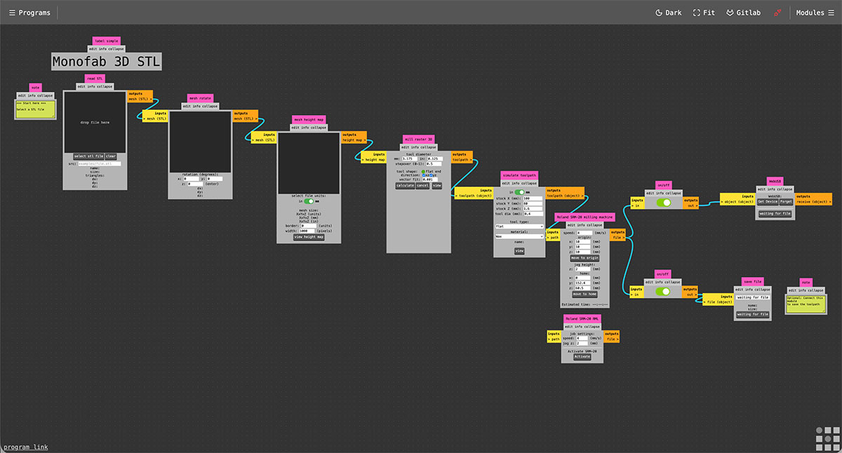
To generate the machining files in .rml format, required for the Roland SRM-20, I used ModsProject ↗️, following a workflow very similar to the one used during the Electronics Production week.
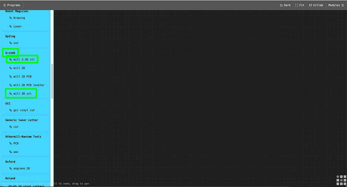
For the roughing process, I selected the “mill 2.5D stl” module, which is suitable for removing large volumes of material efficiently.
For the finishing process, I used the “mill 3D stl” module, which allows a more precise toolpath following the geometry, resulting in a more detailed and refined surface finish.
Rough toolpath
For the roughing process, the first step is to load the .stl file into Mods.
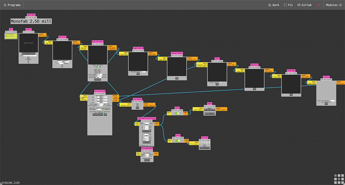
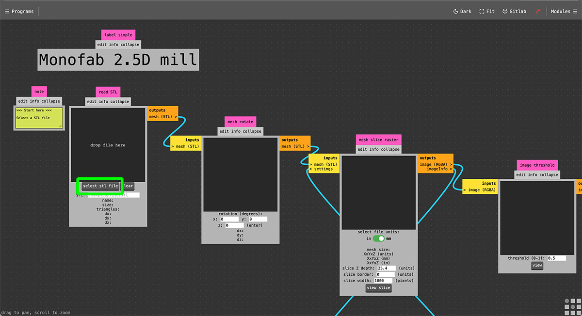
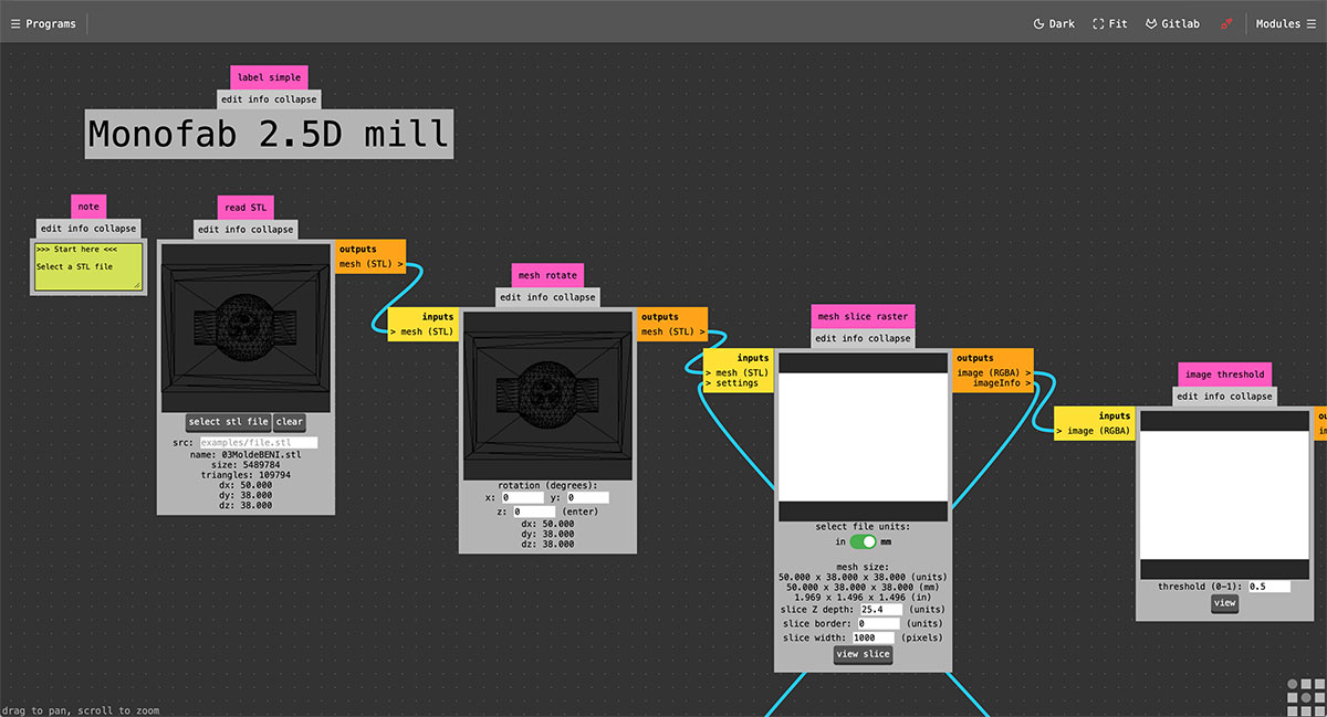
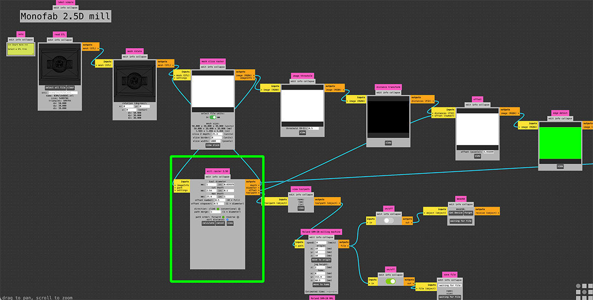
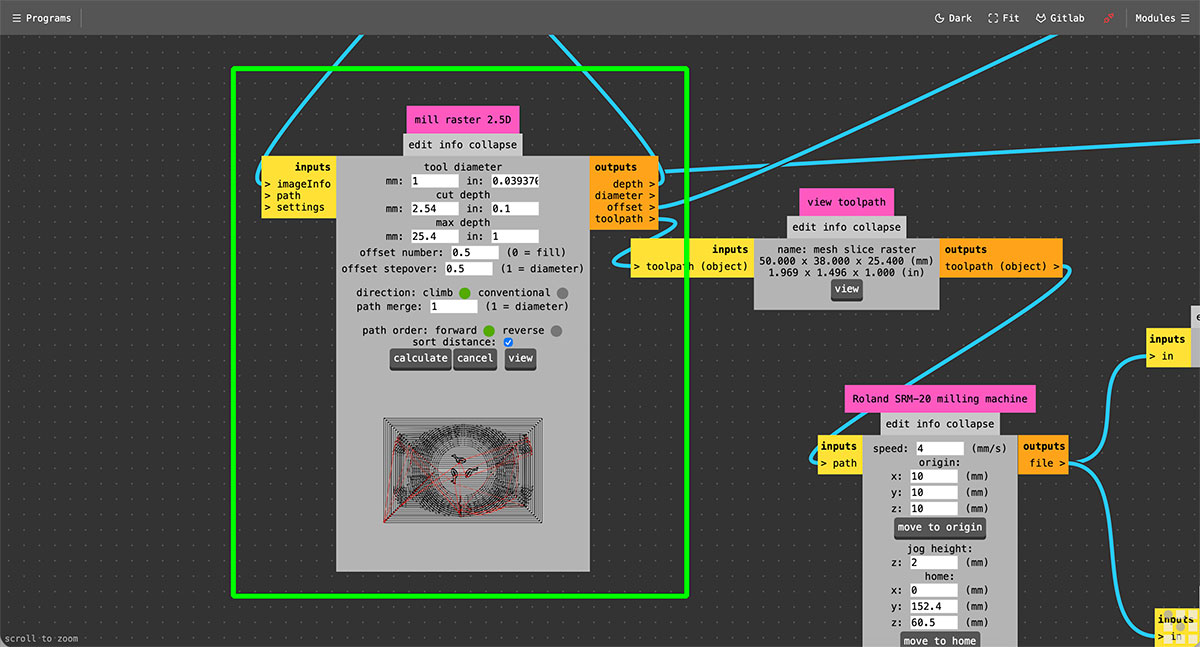
Next, in the “mill raster 2.5D” module, the tool parameters are configured. In this case, I used a 1 mm diameter end mill, setting a cut depth of 2.54 mm and an offset of 0.5. Once these values are defined, the toolpath is generated by pressing the “Calculate” button.
To verify the result, the toolpath can be visualized using the “view” button in the adjacent “view toolpath” module, which allows checking how the machining process will be executed.
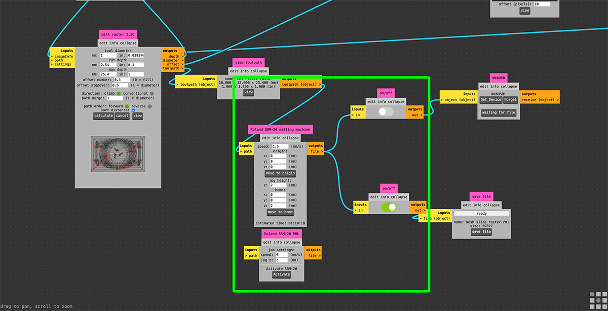
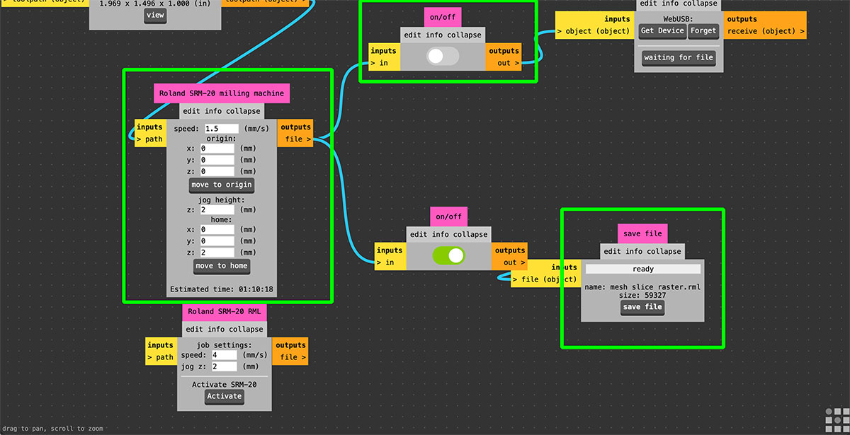
Then, in the “Roland SRM-20 milling machine” module, the machine parameters are set, including the feed rate (1.5 mm/s), the origin point, the jog height, and the home position.
Finally, in my case, it was necessary to disable the “webUSB” output, since the goal is to generate a file in .rml format, which will be later sent to the milling machine.
Finish toolpath
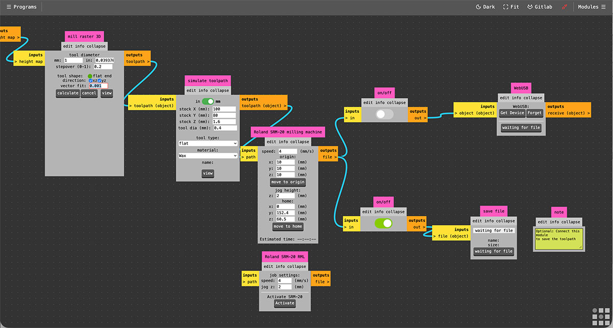
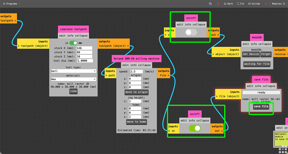
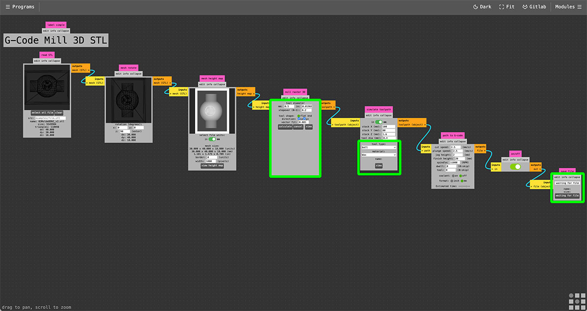
For the roughing process, the first step is to load the .stl file into Mods.
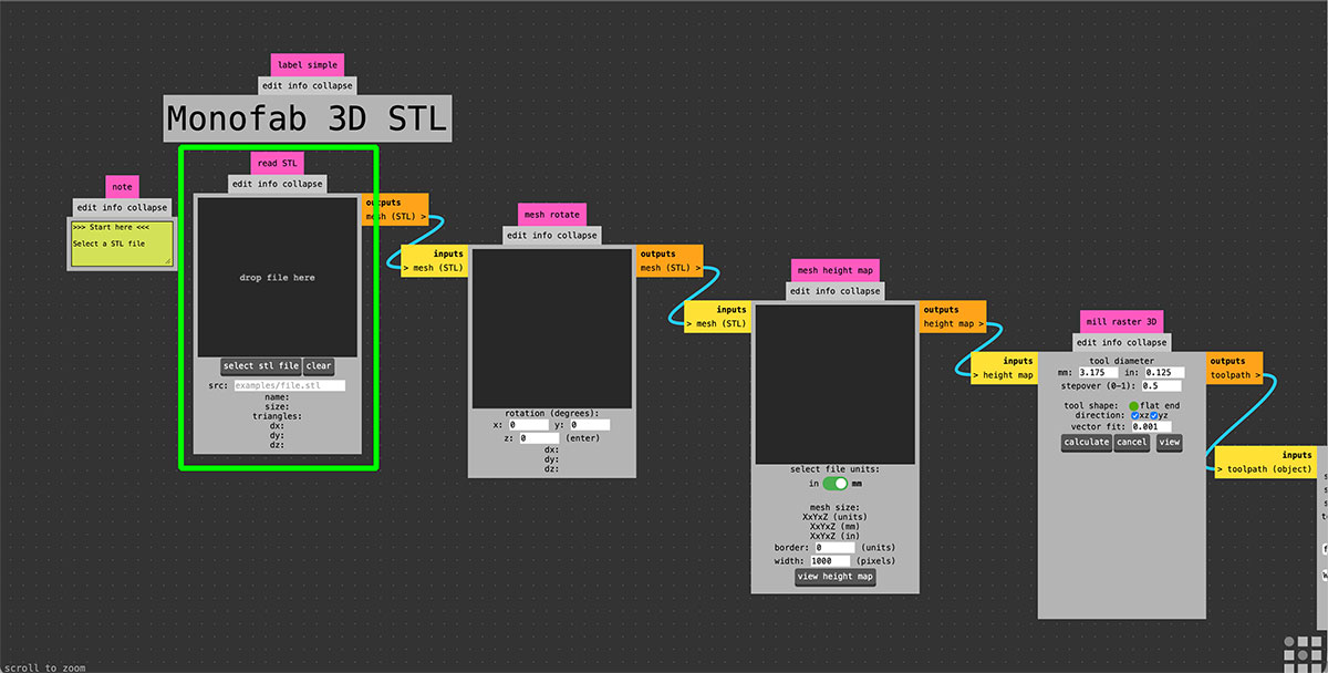
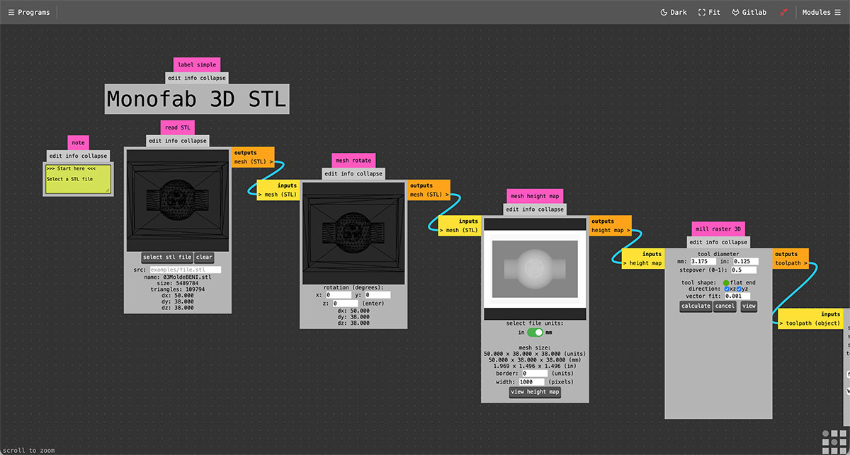
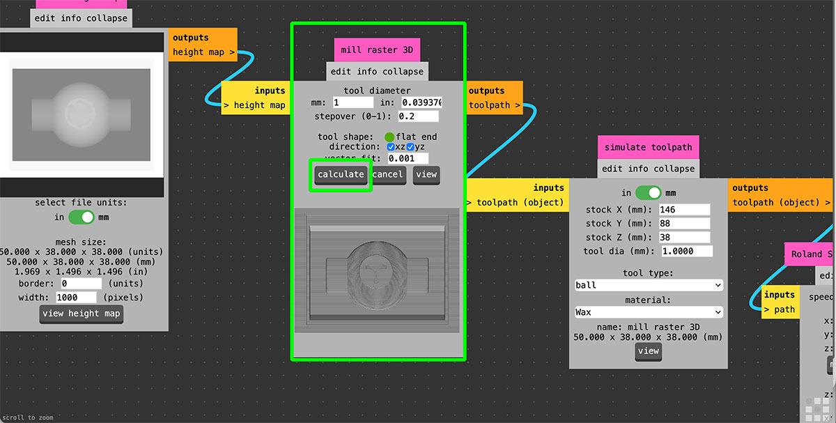
In the “mill 3D stl” module, the tool parameters are configured. In this case, I used a 1 mm diameter end mill and set a stepover of 0.2, which allows achieving a higher level of detail on the final surface. Once these values are defined, the toolpath is generated by pressing the “Calculate” button.
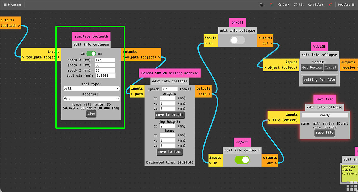
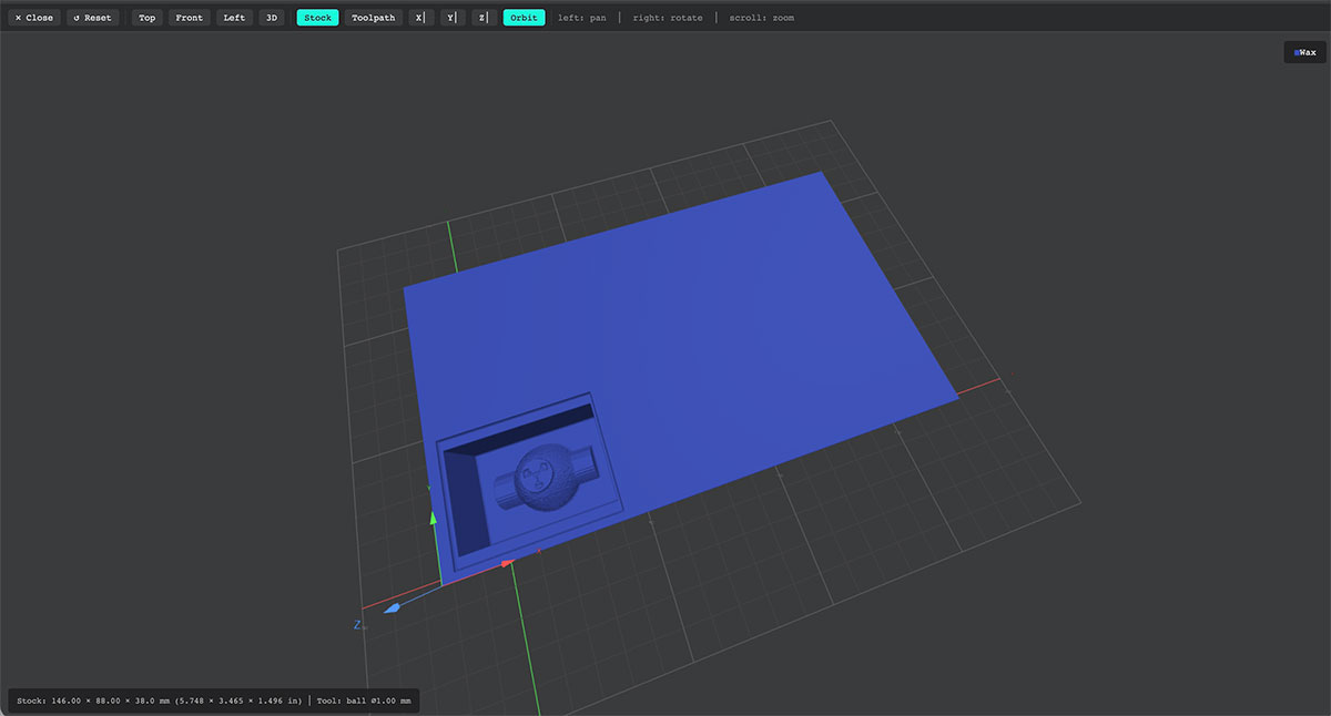
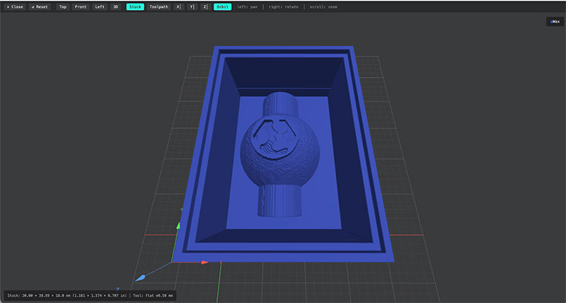
Next, in the “simulate toolpath” module, the dimensions of the material block are defined, along with the tool type and material. By pressing “view”, a preview of the model inside the wax block is generated, allowing visualization of both the available space and the amount of material that will be removed.
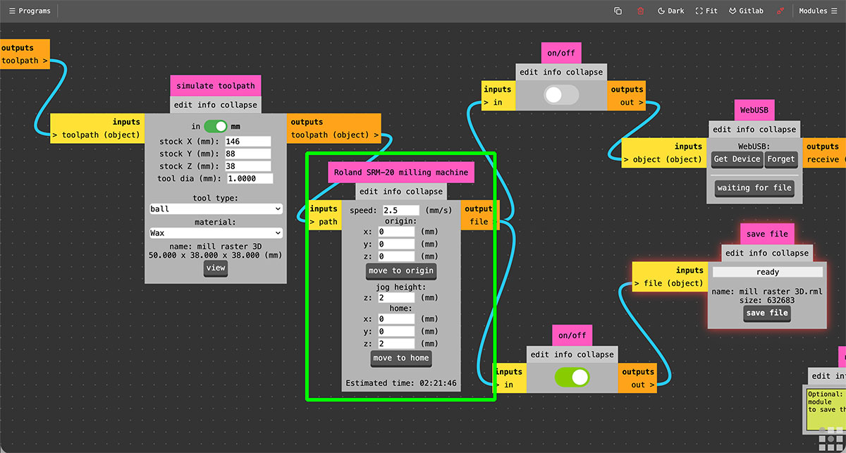
Then, in the “Roland SRM-20 milling machine” module, the machine parameters are configured, including the feed rate (1.5 mm/s), the origin point, the jog height, and the home position.
As in the roughing process, it is necessary to disable the “webUSB” output, since the goal is to generate a file in .rml format.
Finally, by pressing “save file” in the last module, the file “mill raster 3D.rml” is downloaded, which will be used for the finishing milling process.
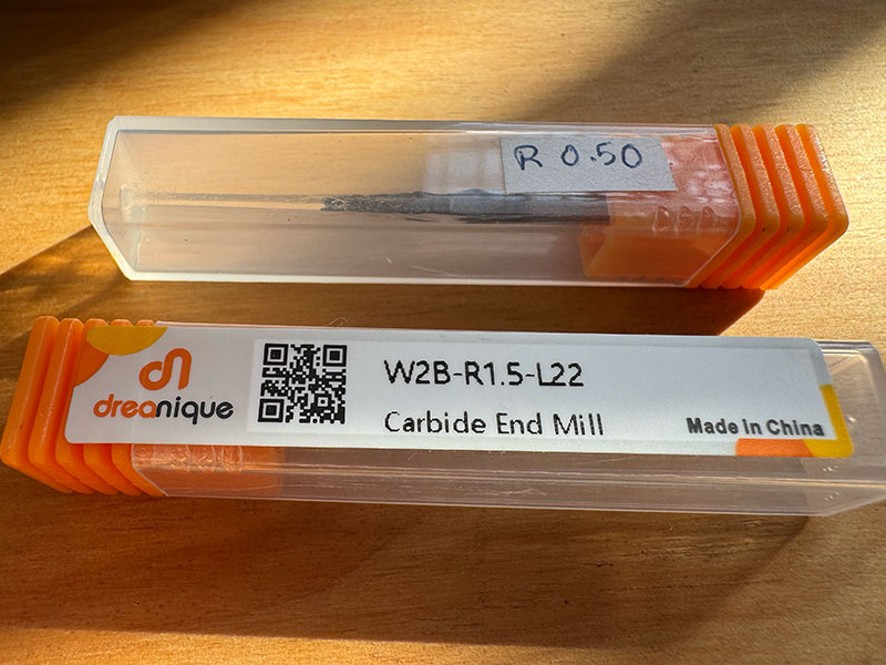
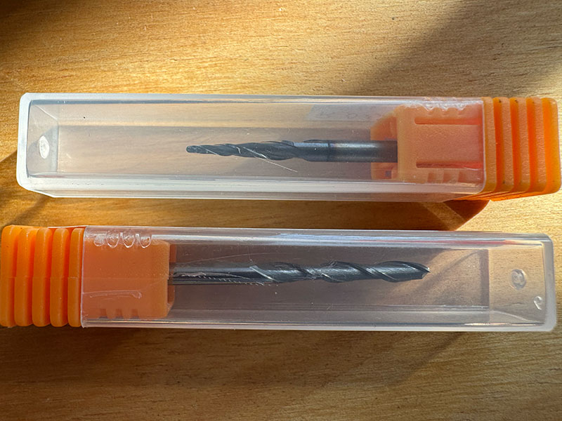
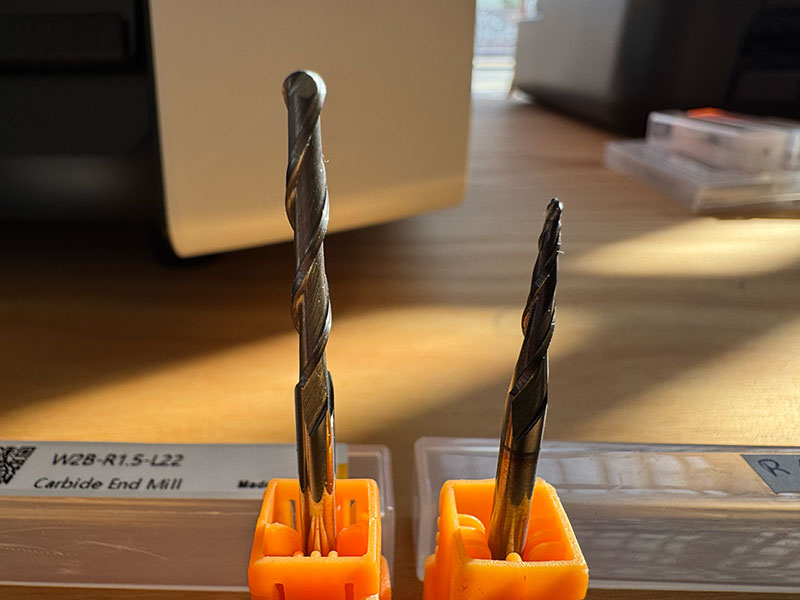
Milling tools
For the mold machining process, two different end mills were selected, each adapted to a specific stage of the workflow.
For the roughing process, a 3.175 mm (1/8”) diameter end mill was used, suitable for efficiently removing larger amounts of material.
For the finishing process, a 0.5 mm diameter end mill was selected, allowing for higher detail and a finer surface finish.
In both cases, the tools are ball nose end mills, made of carbide and featuring 2 flutes, making them well-suited for precision machining in materials such as wax.
Milling the mold
Once both files were generated, the next step was to prepare the Roland SRM-20. The wax block was securely fixed on the machine bed, and the appropriate end mill for the roughing process was installed.
Following the same workflow used during Week 8 (Electronics Production), I opened VPanel and set the origin point (0) for the X and Y axes. Then, I manually adjusted the tool height to also define the Z axis zero.
Once the origin was set, I moved the Z axis approximately 3 mm upwards as a safety margin and reduced the movement speed to start the process in a controlled way.
Next, I loaded the first .rml file corresponding to the roughing process and executed it. As soon as the tool started cutting and everything seemed correct, the feed rate can normally be increased to 100% to optimize machining time.
However, from the very beginning, we encountered significant issues with the machine. The SRM-20 is completely new, but it has not worked properly at any point. In fact, during Week 8 (Electronics Production), we were already unable to mill correctly, so the machine was sent back to the supplier under warranty. After a few weeks, it was returned with the spindle bearings replaced.
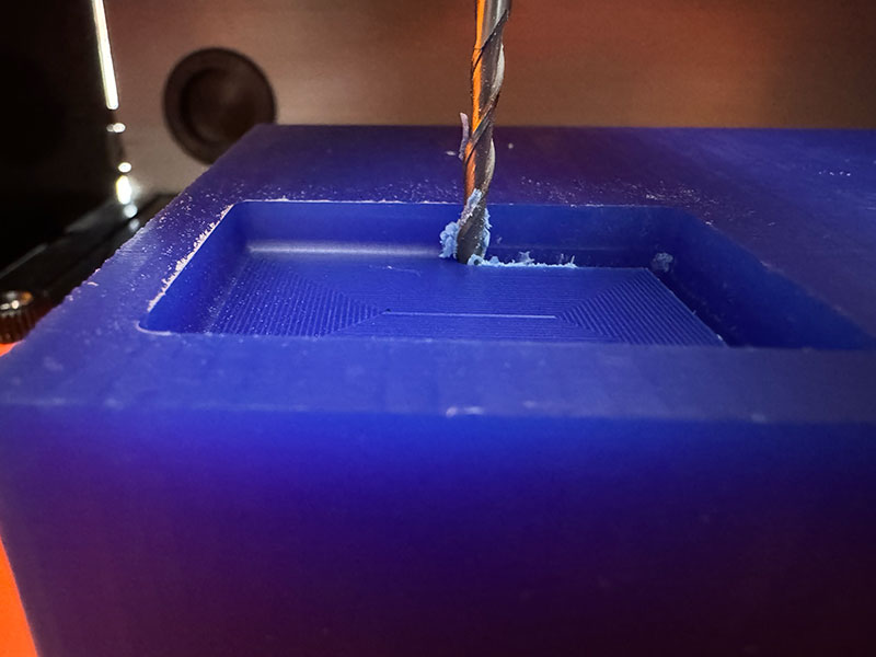
At this stage, the main issue observed was that the machine could not reach the required spindle speed, resulting in insufficient power to mill the wax block using the 3 mm end mill for the roughing process.
High quality video available on my YouTube channel ↗️.
As a test, we tried to reduce the feed rate to the minimum (10%) in order to make material removal easier. During this process, we noticed that the spindle speed gradually increased over time, reaching approximately 5600 rpm, still far from the expected 9000 rpm.
High quality video available on my YouTube channel ↗️.
Despite these attempts, after approximately 4 hours of machining at 10/20% feed rate, the instability in the spindle speed caused the machine to stop. At one point, the spindle lost all its power, the tool stalled, and it became impossible to continue milling the wax block.
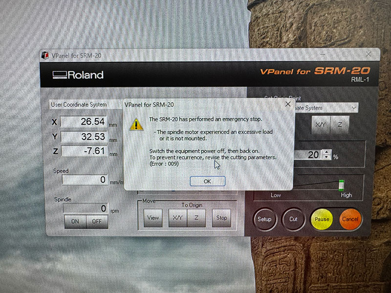
After evaluating the situation, we contacted the supplier again. The machine will be sent back for a second time under warranty, and it is likely that the entire spindle will need to be replaced.
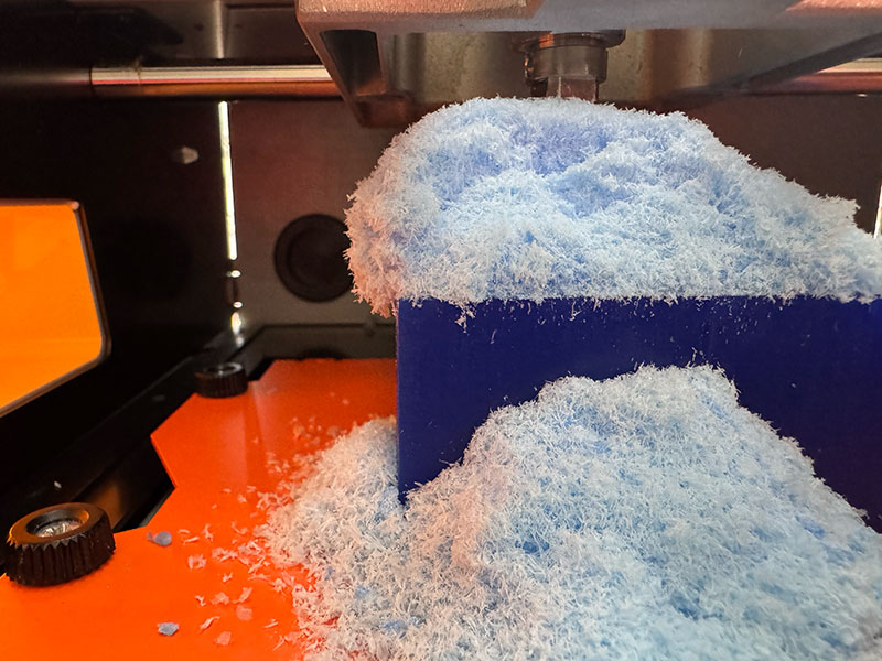
Finally, we removed the piece and proceeded to clean the machine, collecting all the wax debris generated during the process. This material was stored to be reused in future tests by melting it again and creating a new mold.
Under normal conditions, once the roughing process is completed, the next step would be to run the finishing toolpath, changing the end mill and resetting the Z axis zero (while keeping the X and Y origin unchanged). However, due to the issues described, this stage could not be completed.
Milling backup
In parallel with the tests carried out using the SRM-20, we shared the .stl mold design file with the local instructors at FabLab León, who milled a scaled-down version of the mold.
To speed up the process, only the finishing toolpath was executed, and in a single direction. This approach reduces machining time, although the final result does not achieve a perfect surface finish.
This approach allowed us to have a machined physical reference and continue with the workflow despite the limitations experienced with our machine.
Lunyee CNC
Another alternative we explored was setting up a Lunyee CNC, which was provided by FabLab León.
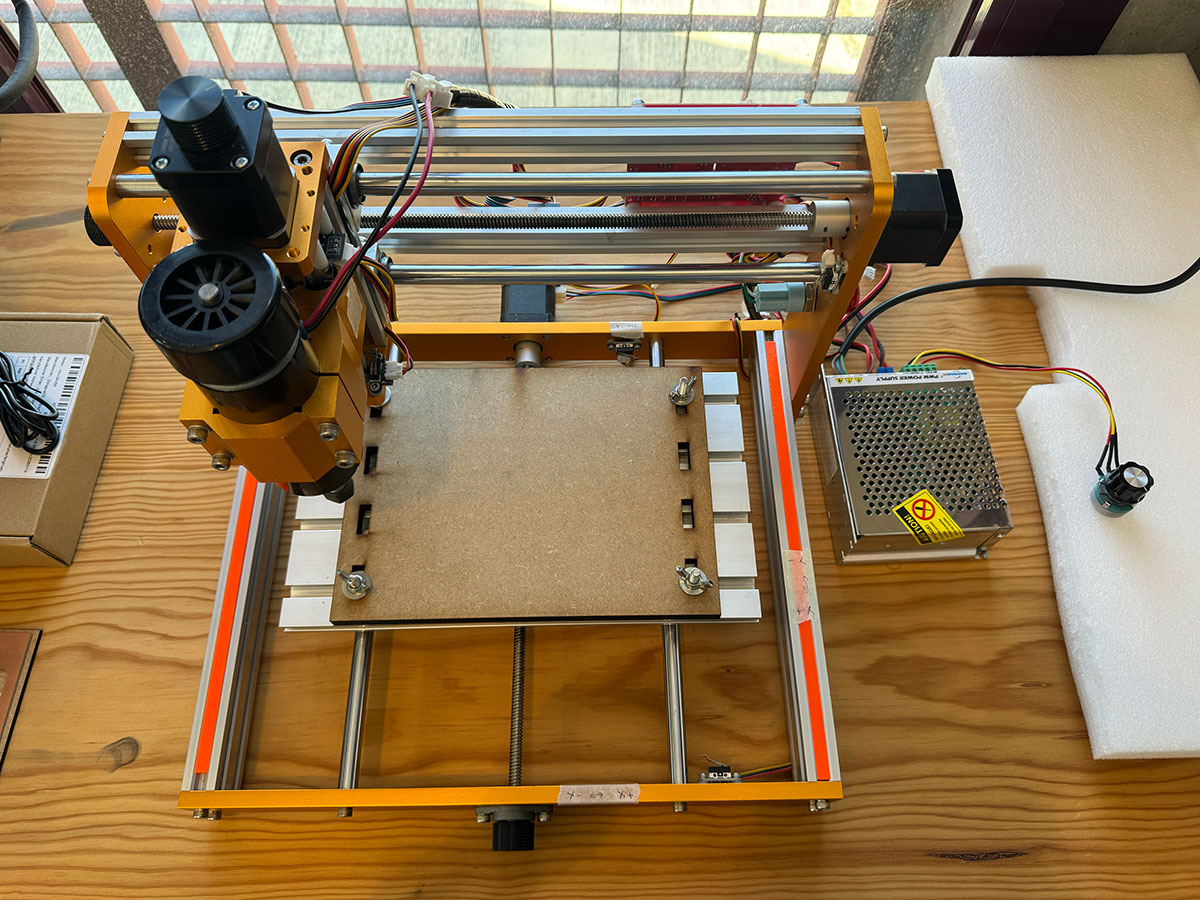
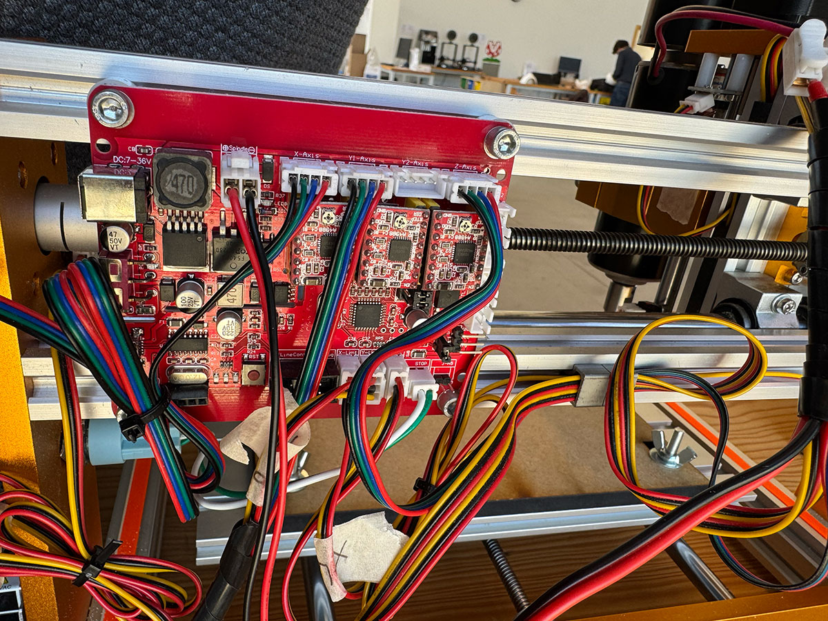
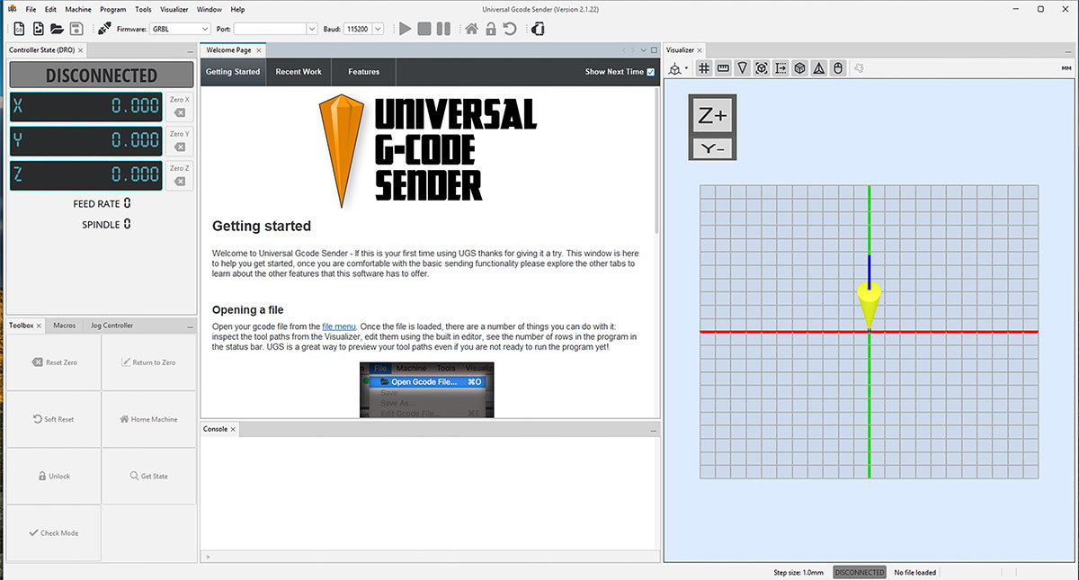
In this case, we used ModsProject again to generate the machining files (GCode) and Universal GCode Sender (UGS) to control the machine.
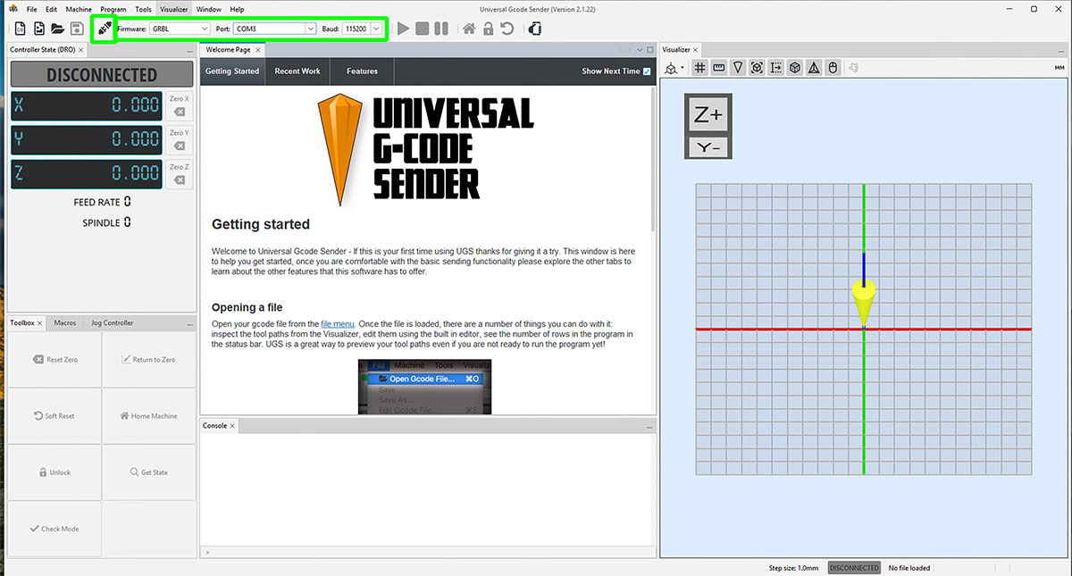
After installing UGS, we connected the machine by selecting GRBL as firmware, choosing the corresponding USB port, and setting the baud rate to 115200. Once configured, we established the connection from the software.
Upon connecting, GRBL displayed an alarm, which is expected since the limit switches were not connected. To unlock the machine and continue working, we executed the $X command.
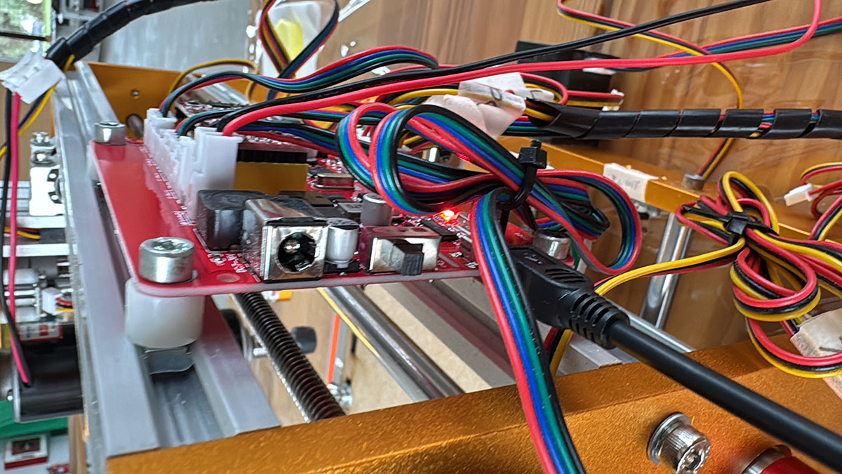
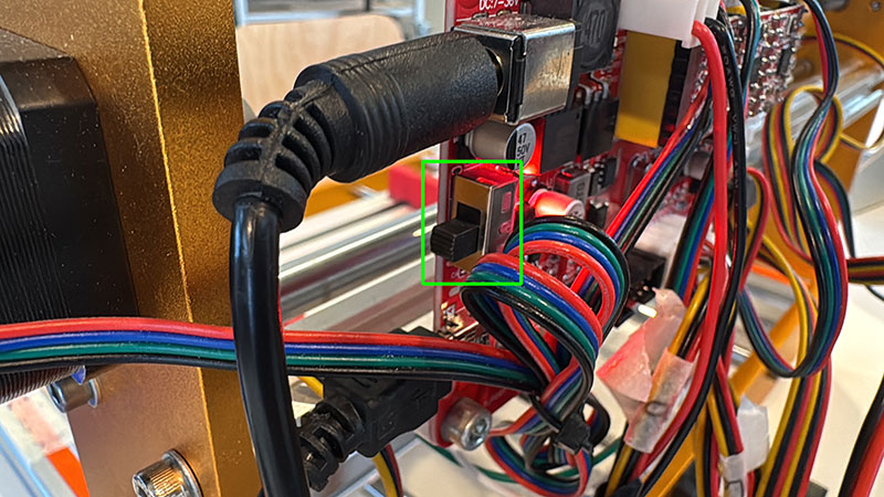
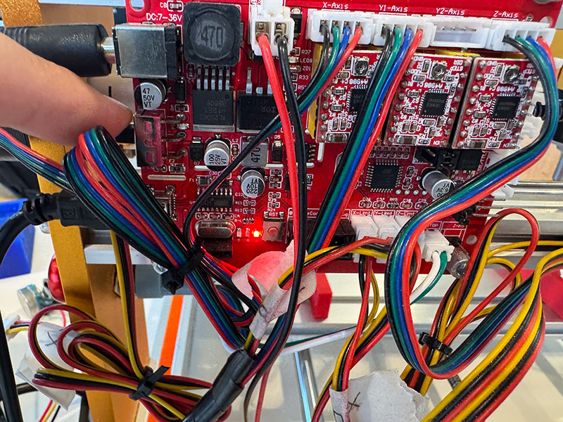
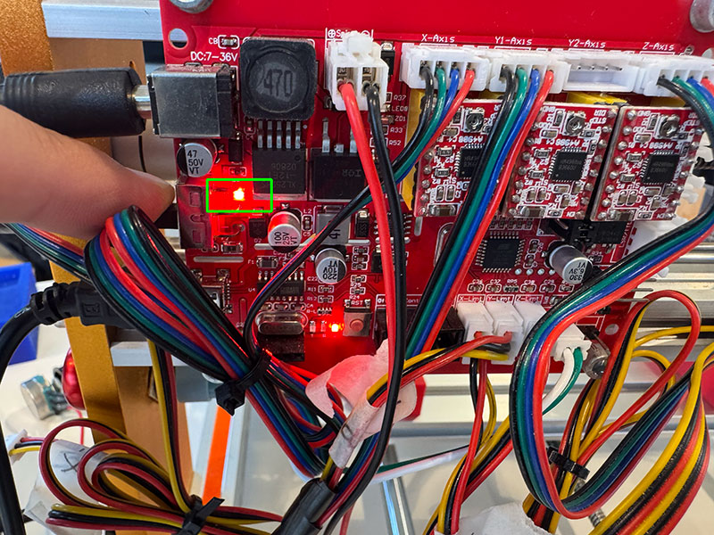
During the setup process, we encountered an issue where the axes could not be moved from UGS. After troubleshooting, we realized that the control board power had not been turned on. Even though some LEDs were lit when connecting the USB cable, we had overlooked that the shield includes an independent power switch.
Once this issue was resolved, we proceeded with the machine calibration, a critical step to ensure accurate movements.
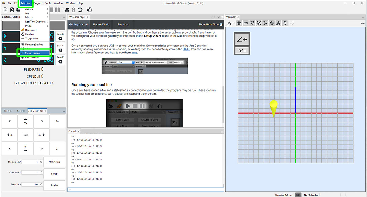
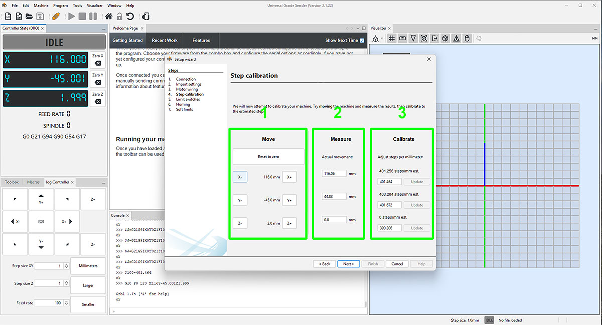
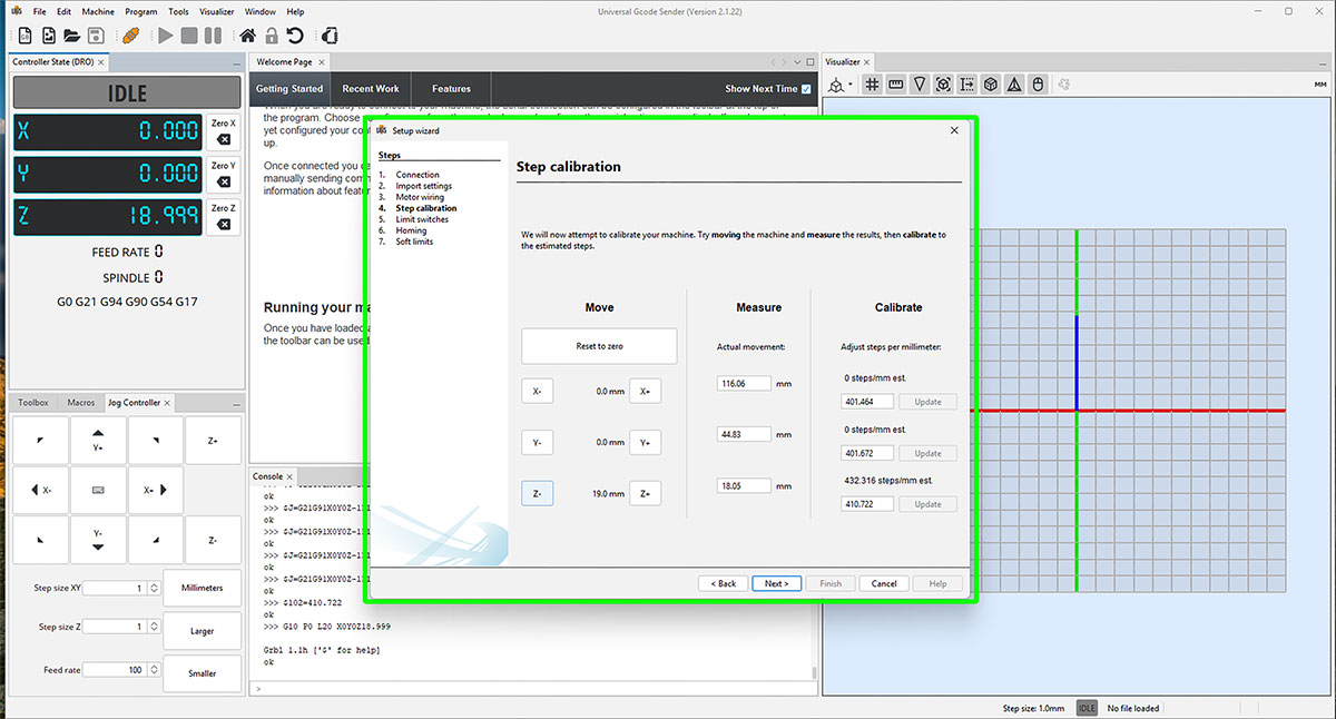
From the “Machine” menu, we accessed “Setup wizard…” and selected “Step calibration”. The process consists of performing controlled movements on each axis and measuring the actual displacement in order to apply the necessary correction.
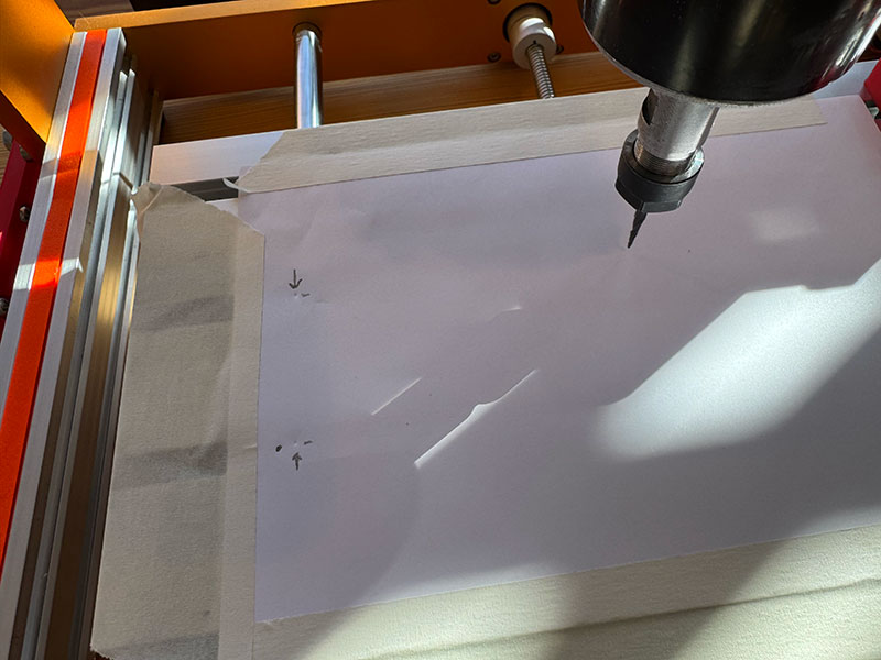
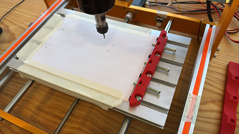
For the X and Y axes, we placed a sheet of paper fixed to the machine bed and, using the tool, made small marks to define the start and end points. This allowed us to accurately measure the real displacement.
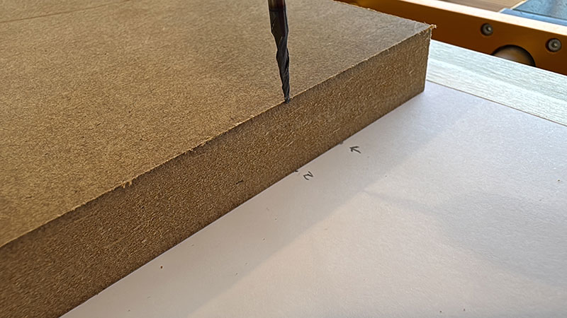
For the Z axis, we brought the tool down until it touched the base, then raised it to the height of the selected material (in this case, 30 mm) and used this reference to perform the calibration.
The process involves entering a theoretical movement value in the “Move” column (for example, 10 mm). Then, the actual measured displacement is entered in the “Measure” column. The system calculates the required steps in the “Calibrate” column, and by pressing “Update”, the correction is applied.
This procedure is repeated for all three axes, ensuring accurate machine behavior.
Once the machine was calibrated, we returned to ModsProject to generate the machining files, following a workflow very similar to the one used previously with the Roland SRM-20.
In this case, instead of selecting a specific machine, we used the generic “G-Code” output module.
For the machining strategies, we used:
- “mill 2.5D stl” for the roughing process
- “mill 3D stl” for the finishing process
The modules and parameters in both setups are almost identical to those used previously with the SRM-20, keeping the workflow consistent.
In this particular case, we decided to run only the finishing toolpath.
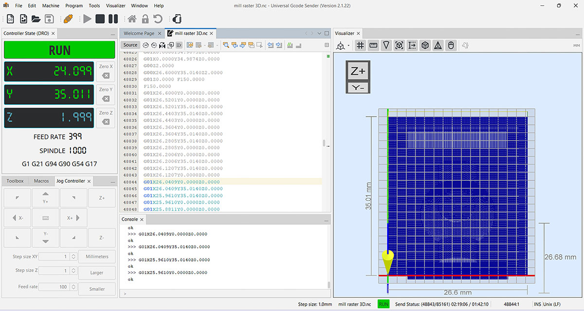
Once the GCode (.nc) file was generated, it was loaded into Universal GCode Sender (UGS) and executed by pressing the “PLAY” button.
High quality video available on my YouTube channel ↗️.
This is the result
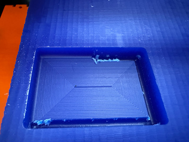
3D printed mold
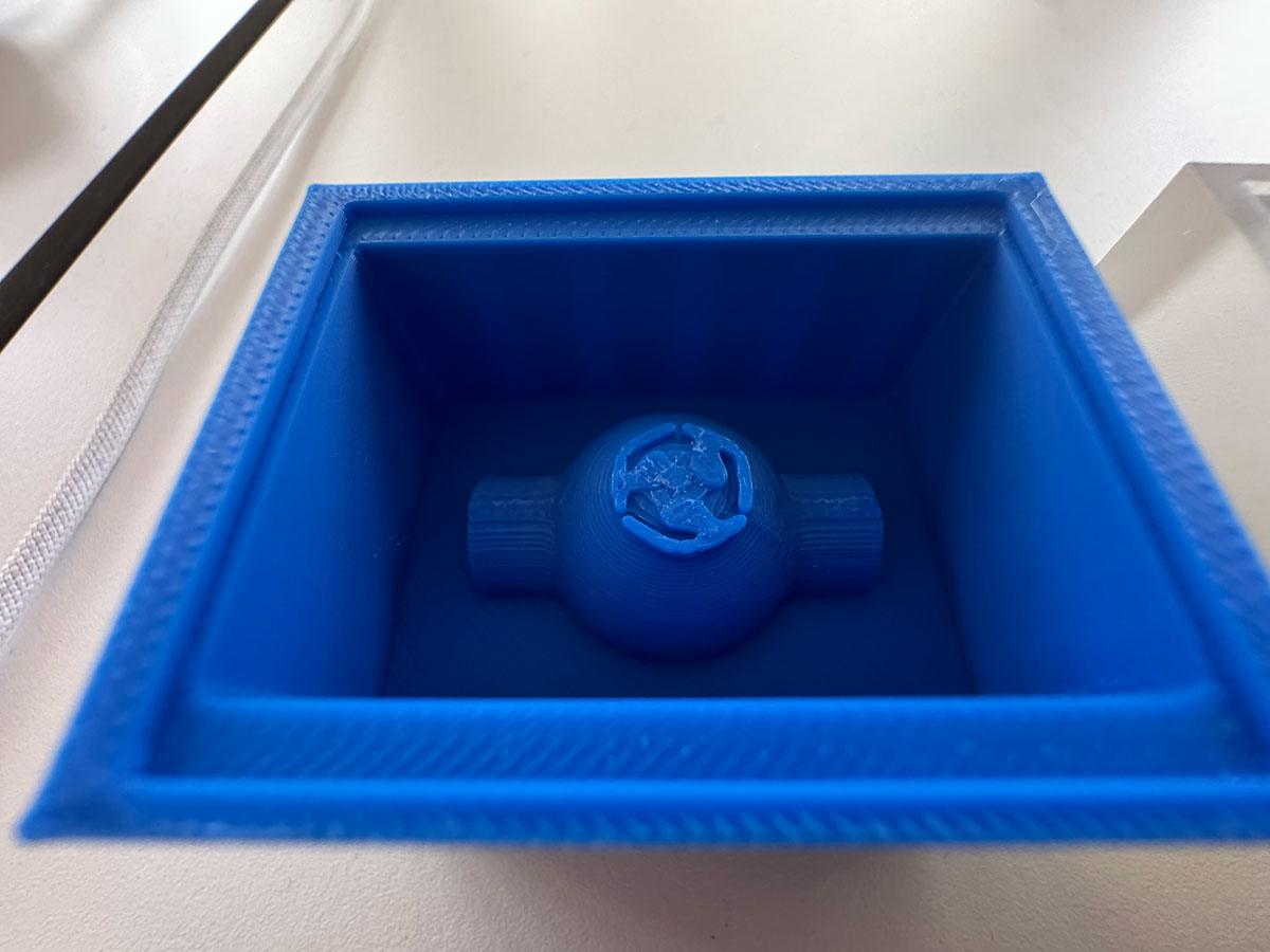
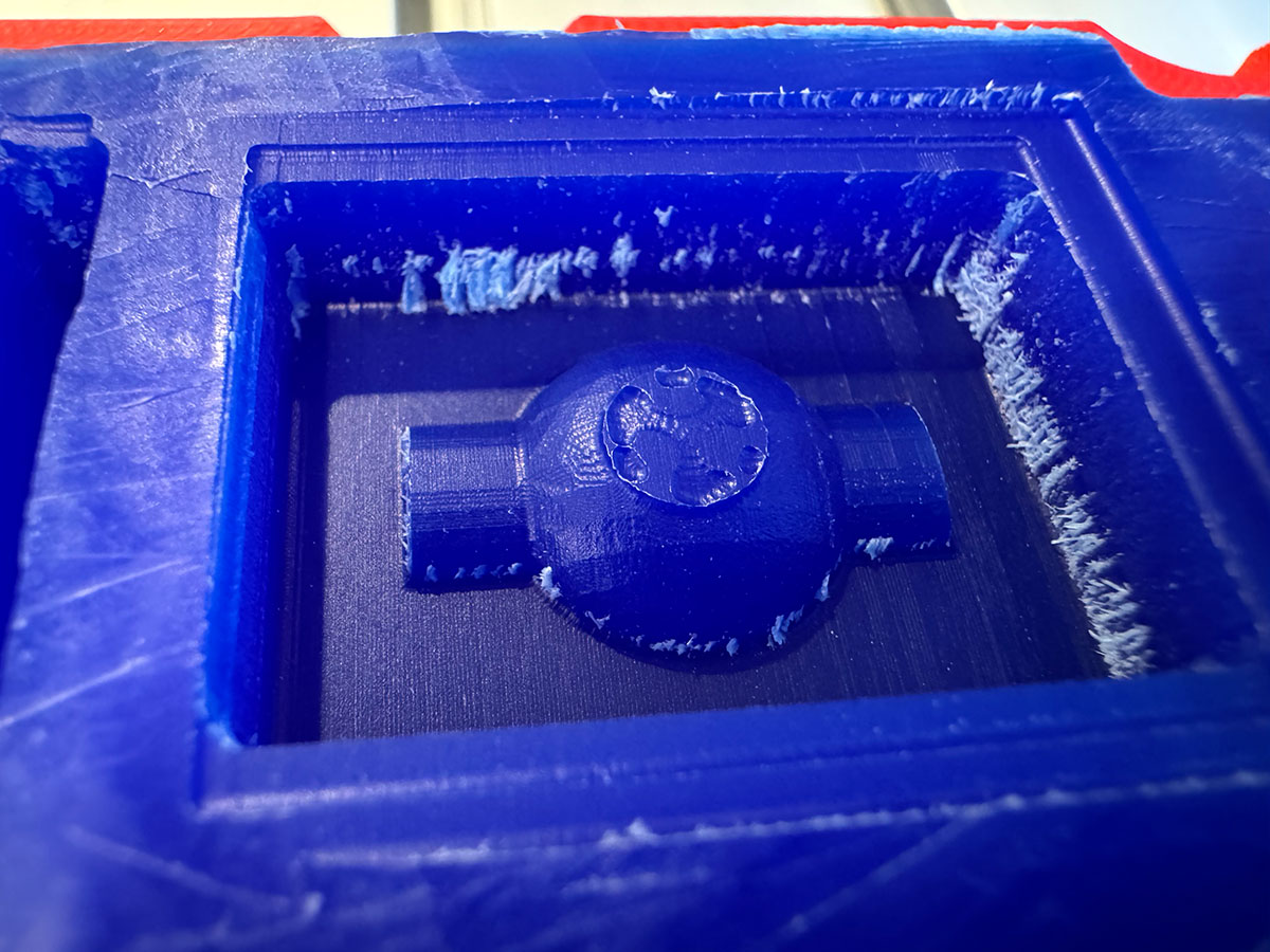
As an alternative to milling, I decided to test the mold fabrication using 3D printing.
In a first attempt, I printed the model using filament. This test allowed me to quickly confirm that, as expected, this method is not suitable for this application, due to the inherent limitations of the extrusion process. The resolution and surface finish are not sufficient to achieve the level of detail and precision required for a proper mold.
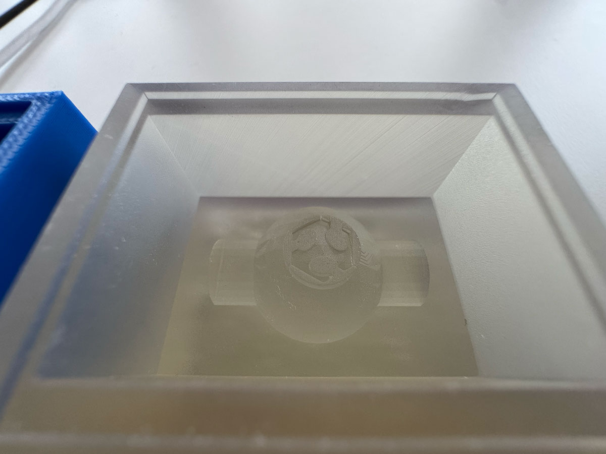
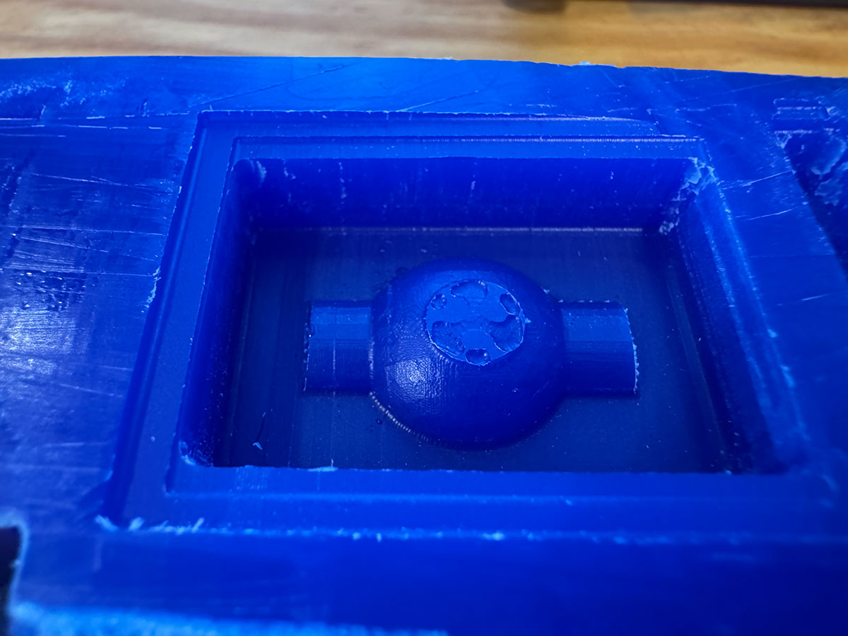
Based on this result, I switched to a different approach and performed a second test using resin 3D printing. In this case, I followed the same workflow and used the same materials as in Week 5 (3D Scanning and Printing).
The result was clearly much better, achieving a mold with a significantly finer and more precise surface finish, suitable for continuing with the molding process.
Make a SILICONE mold
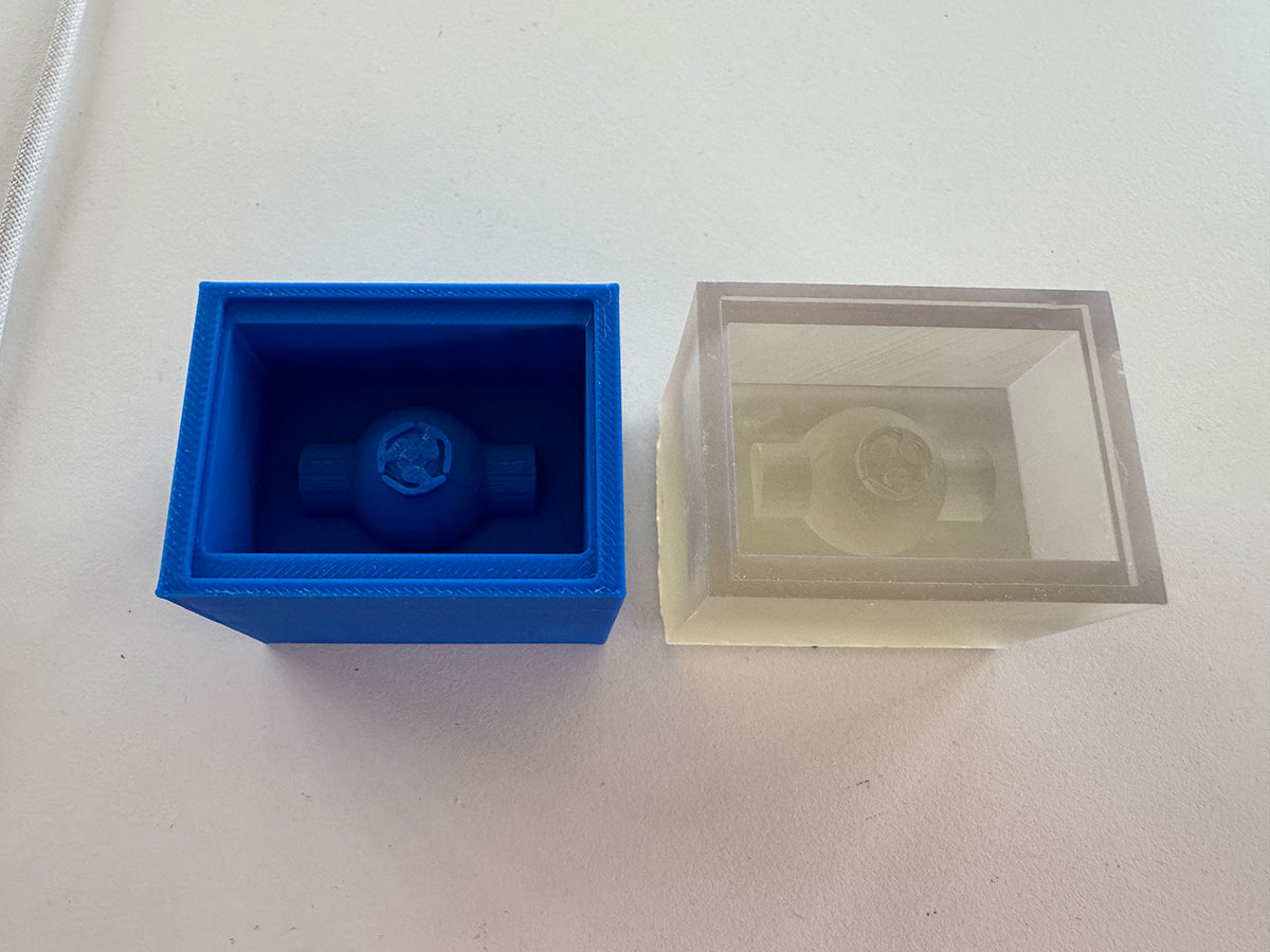
Resin
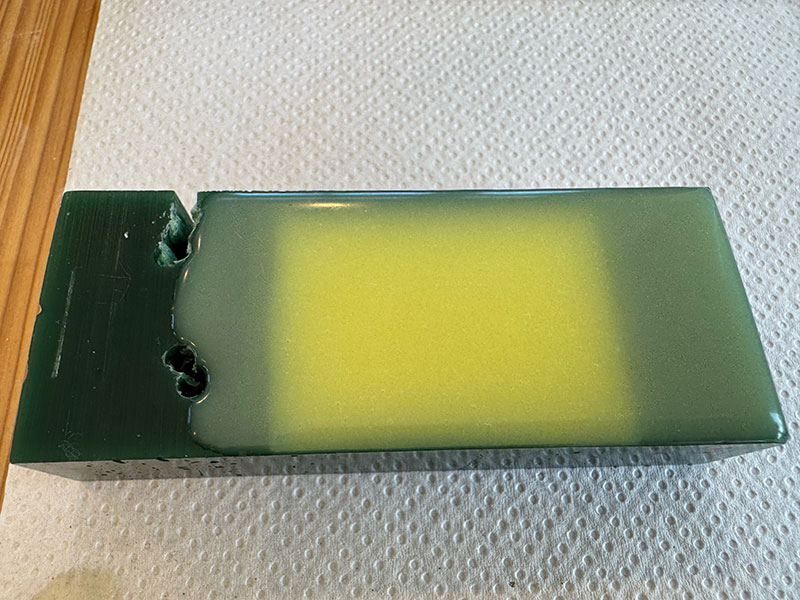
Using the previously fabricated resin mold, the next step was to attempt creating a silicone negative mold from it.
For this process, I used the silicone analyzed during the group assignment, specifically Reschimica R PRO 30 (Silicone Rubber).
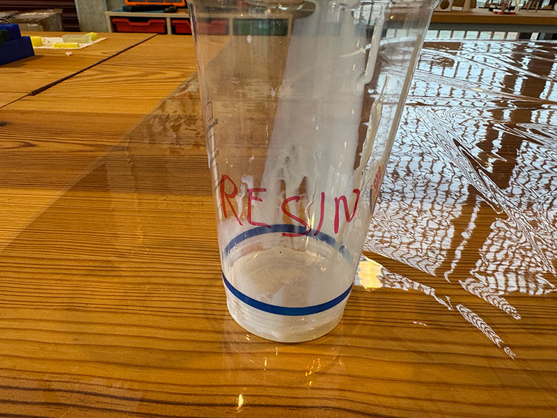
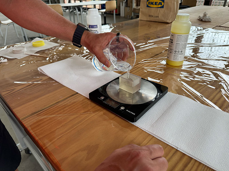
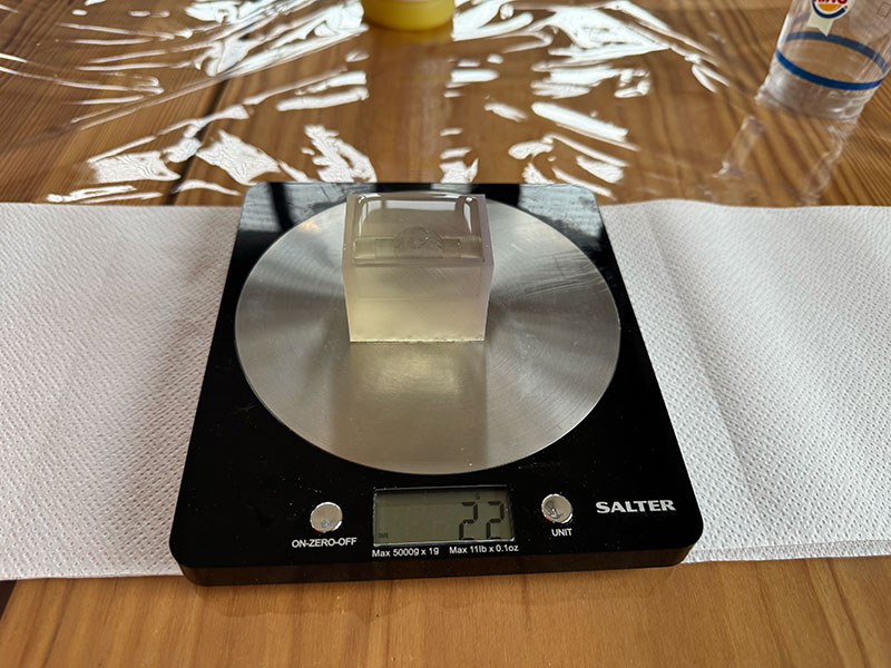
Before preparing the mixture, I performed a simple test by filling the mold with water in order to estimate the required volume (and therefore weight) of material. Although silicone has a higher density, this serves as a useful initial approximation.
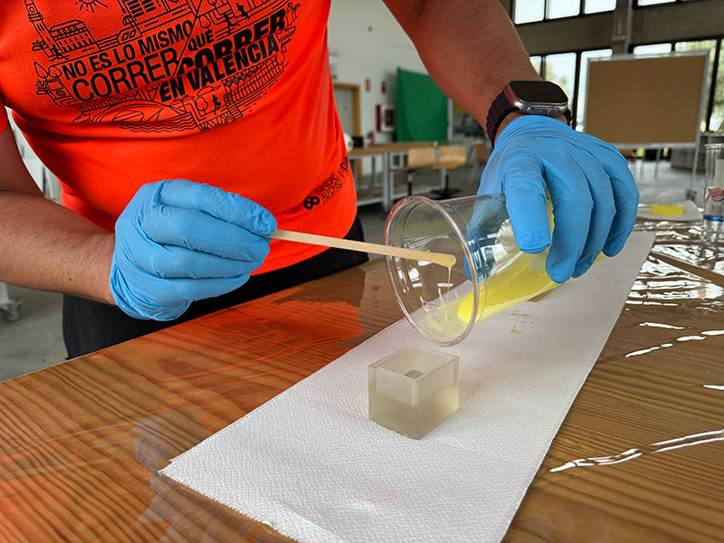
Next, I prepared the mixture by adding component A and the same proportion by weight of component B, following the manufacturer's instructions. A homogeneous mix is essential to ensure proper curing of the material.
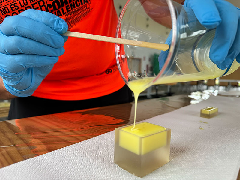
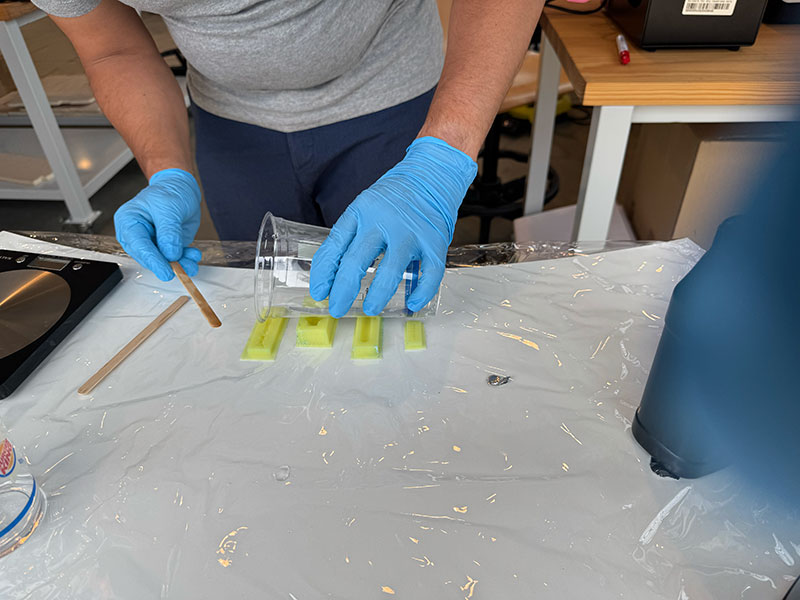
Once both components were properly mixed, I poured the silicone into the resin mold until the geometry was completely covered.
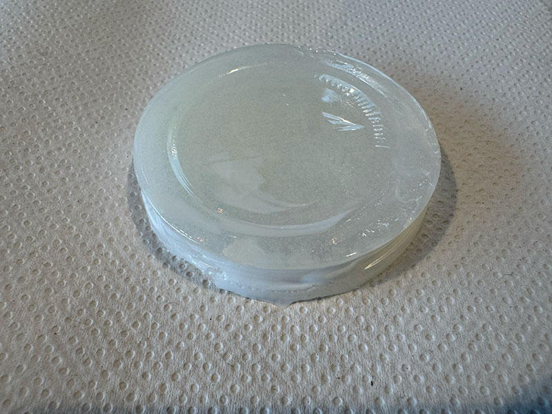
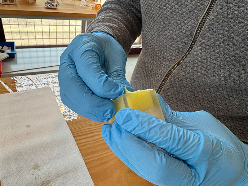
However, after leaving the material to cure for the recommended time (around 24 hours), it became clear that the silicone did not cure properly. Instead of solidifying, it remained sticky, indicating that the curing process had failed.
This behavior is relatively common when working with resin 3D printed molds. Many SLA/DLP resins can inhibit silicone curing due to the presence of residual photoinitiators, uncured monomers, or compounds such as sulfur and amines on the surface. These substances interfere with the chemical reaction of the silicone, preventing proper polymerization.
This test was intentionally carried out to verify this behavior, confirming that under these conditions, the silicone does not cure correctly on this type of surface.
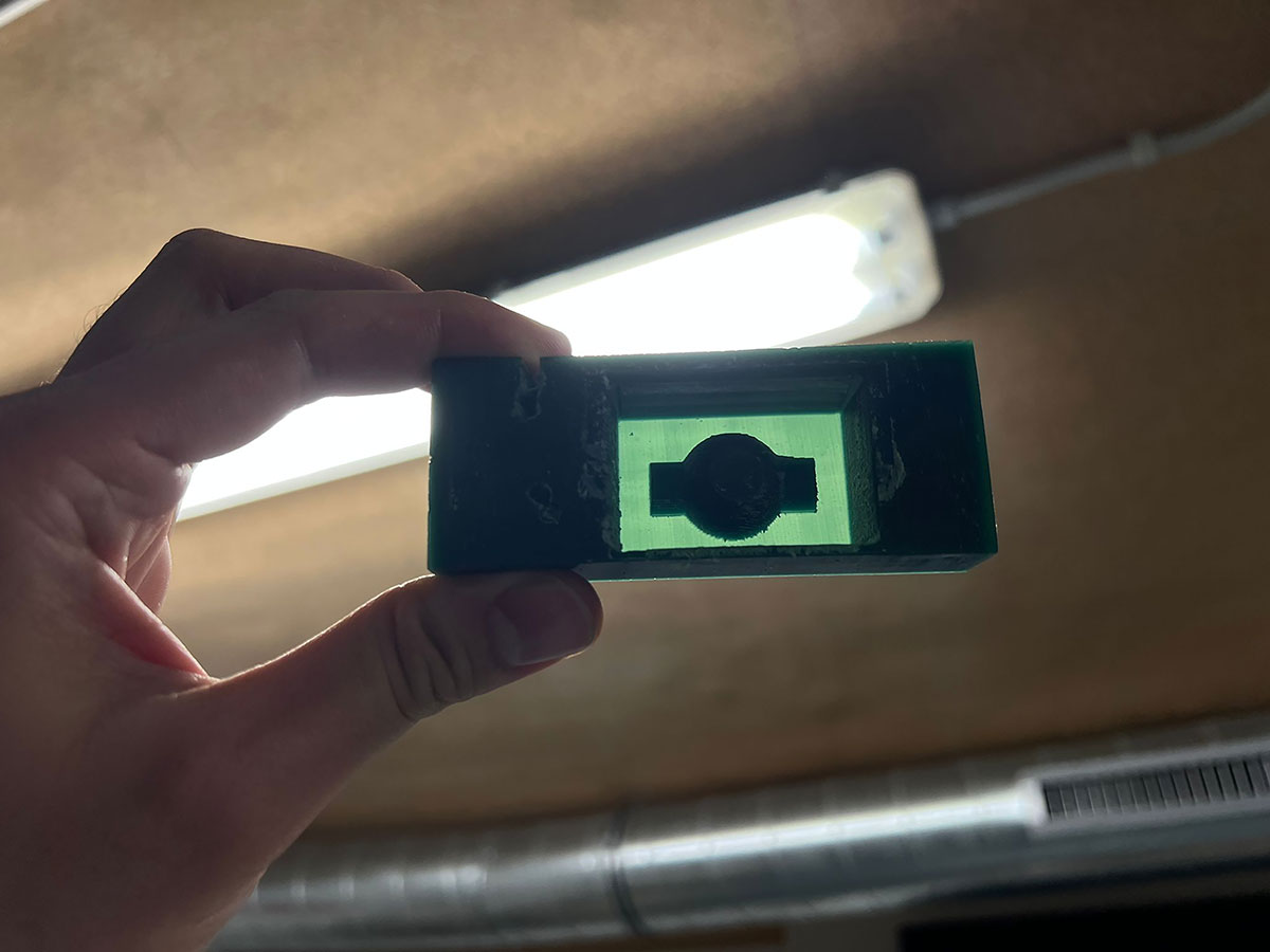
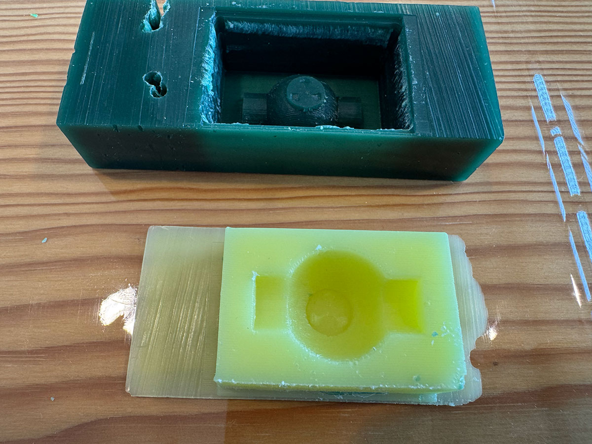
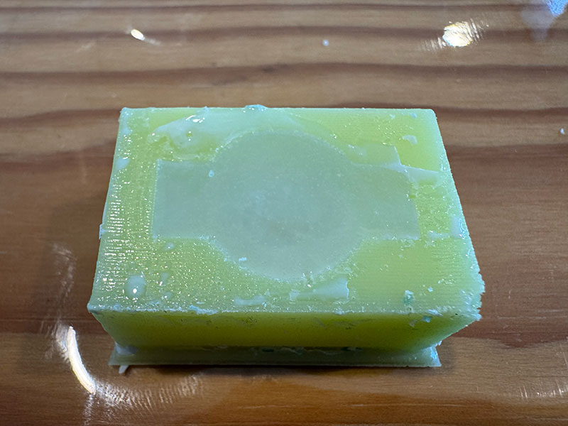
Wax
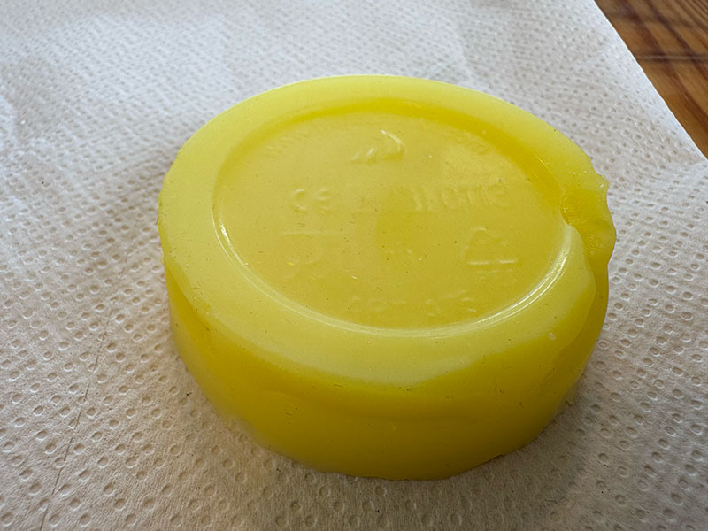
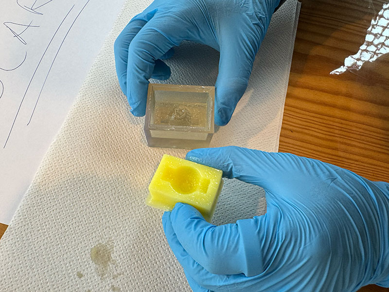
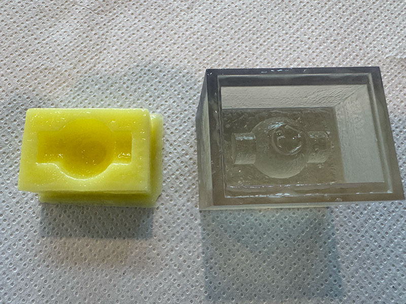
After the issues encountered with the resin mold, the next step was to create the silicone mold using the wax mold, following the same procedure and using the same silicone as in the previous process.
In this case, working with wax avoids the chemical incompatibilities observed with resin. This allows the silicone to cure properly, as wax is a much more stable material and does not interfere with the polymerization process.
This second attempt therefore represents a more reliable approach to obtaining a functional silicone mold.
The result
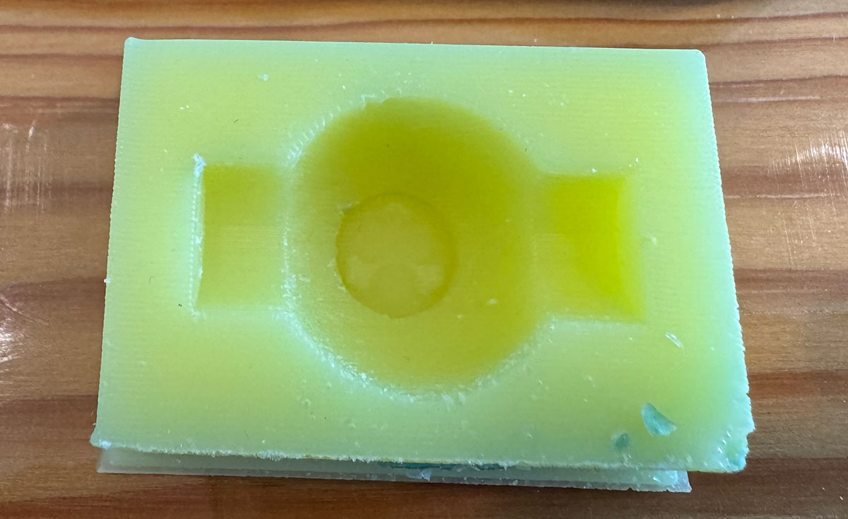
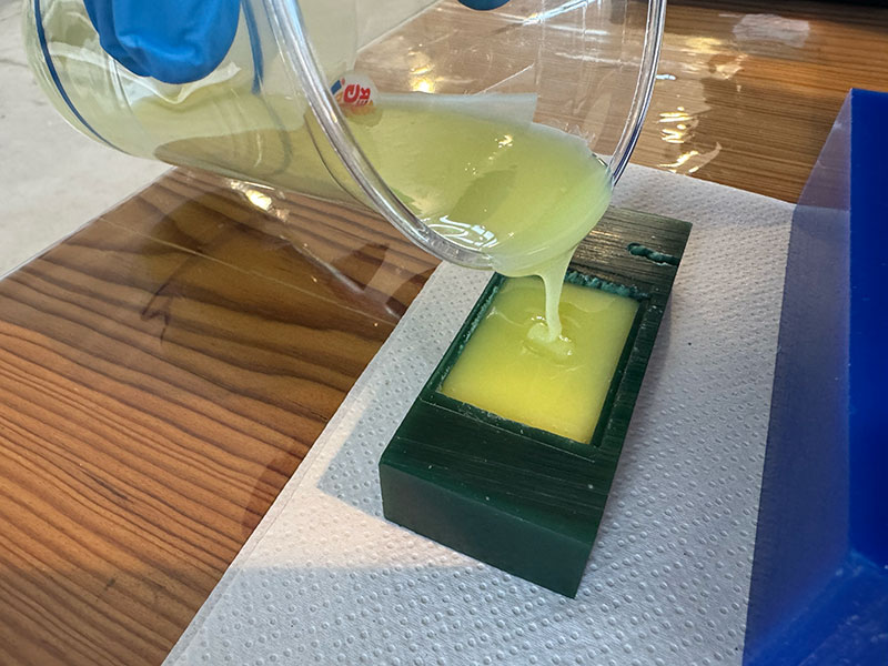
Casting
With the silicone negative mold already prepared, it was time to start producing the first castings using different materials.
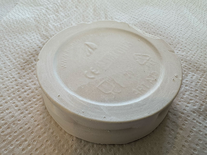
Plaster casting
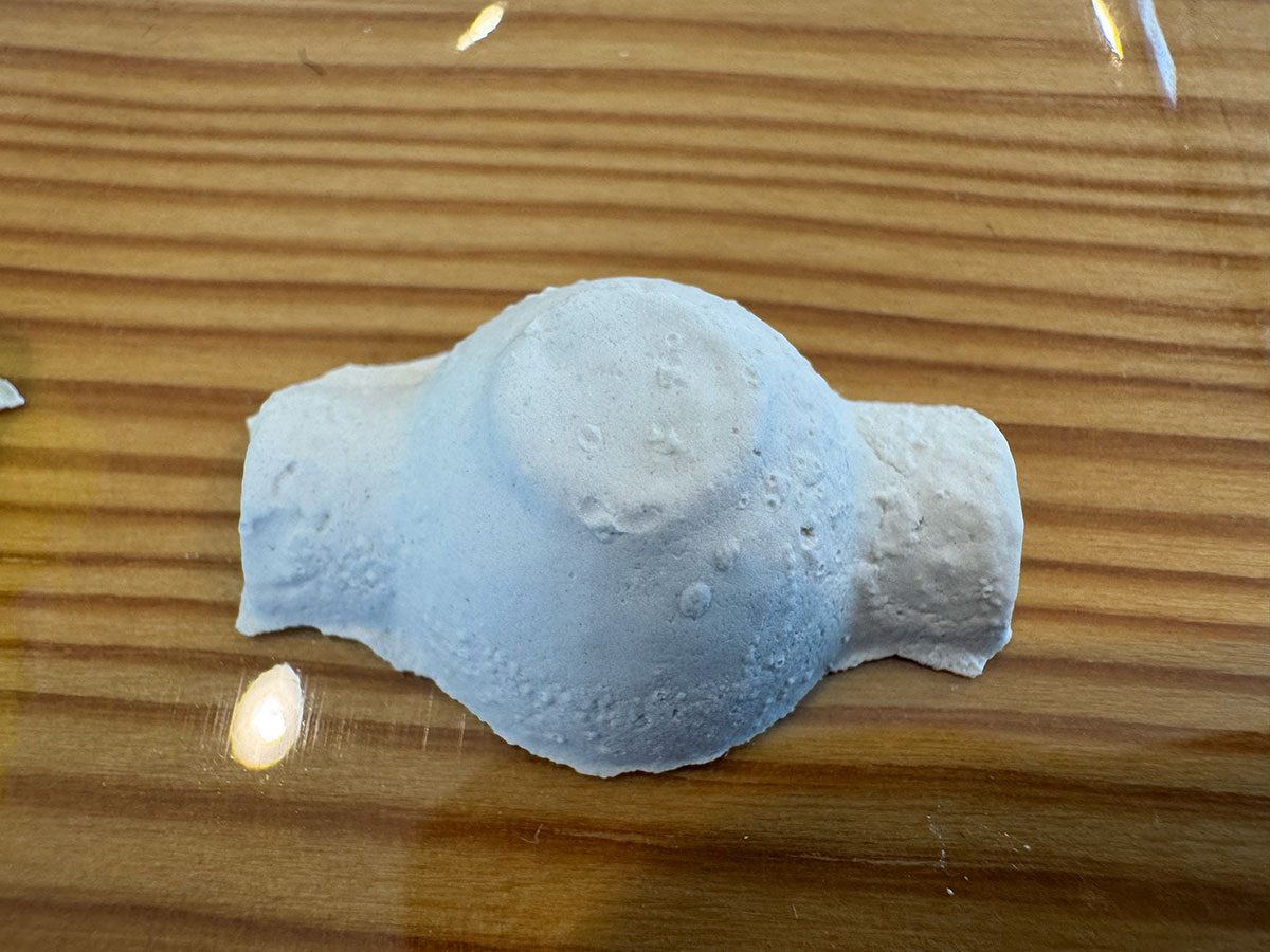
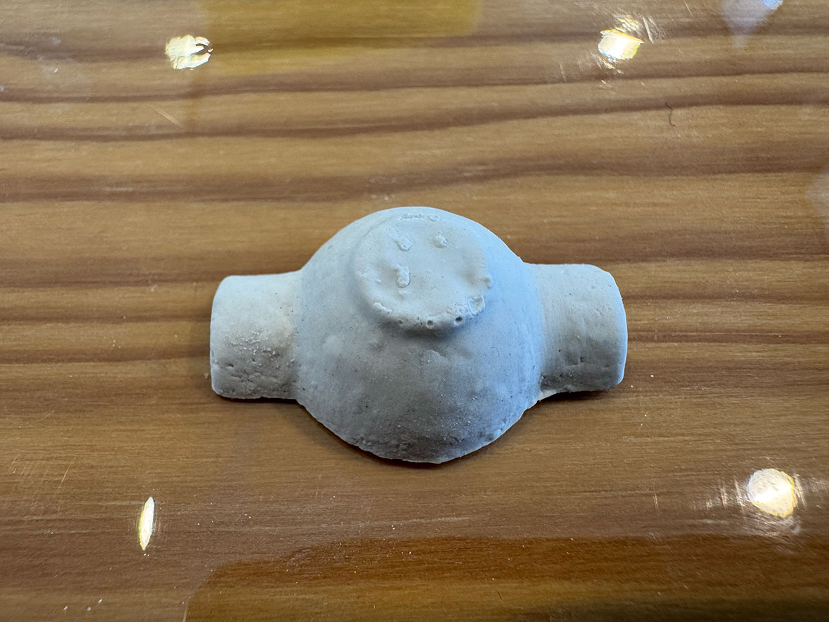
As a first step, I made a casting using plaster in order to obtain a first physical piece.
Following the manufacturer's instructions (and the same procedure used during the group assignment material test), I prepared the mixture of plaster and water in a 1:0.7 ratio. Once a homogeneous mixture was achieved, I poured it into the silicone negative mold.
After filling the mold, I removed the excess material to level the surface and left the piece to rest for the recommended curing time.
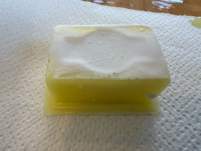
This is the result obtained.
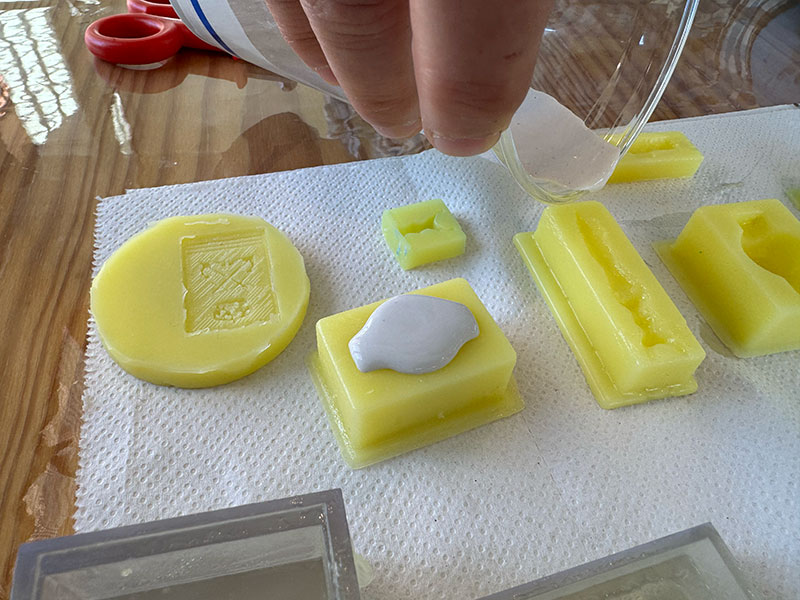
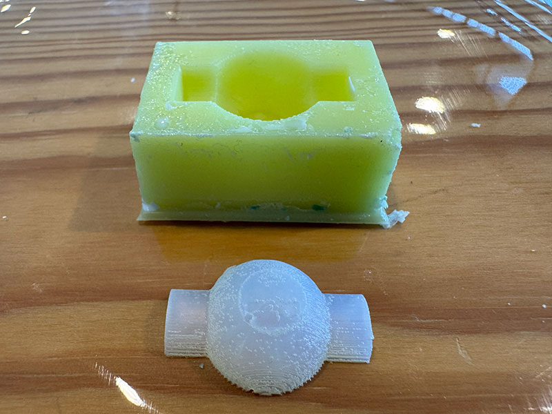
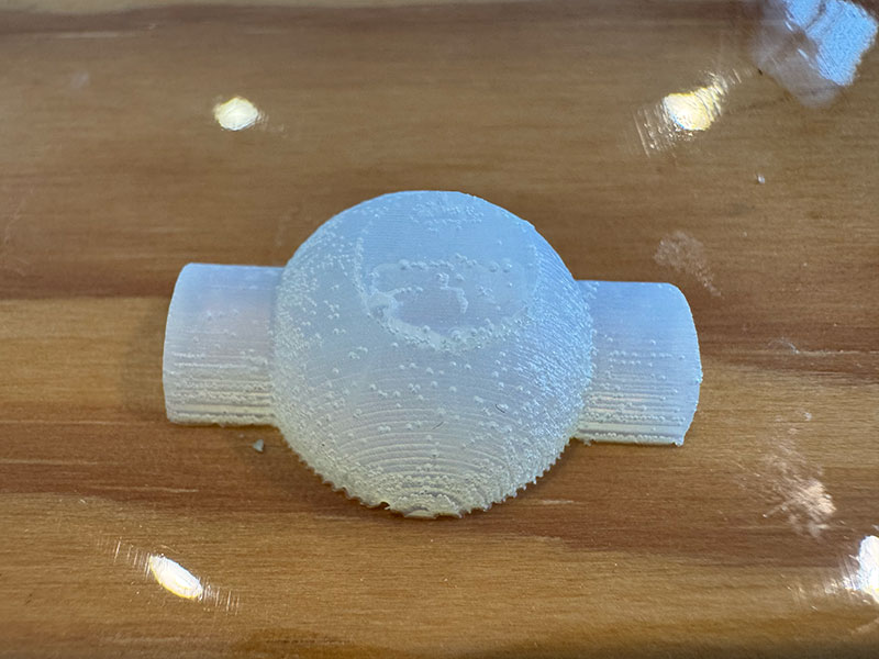
Resin casting
Next, it was time to work with resin.
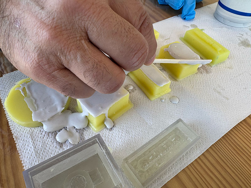
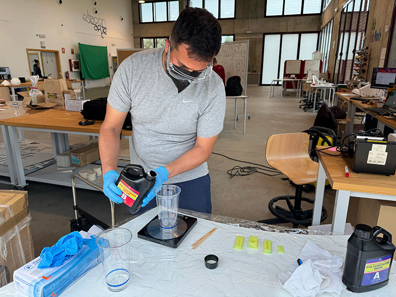
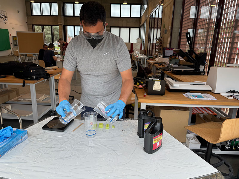
Following the manufacturer's instructions, and using a 1:1 ratio, I weighed component A and the same amount of component B. Respecting this ratio is important to ensure proper curing.
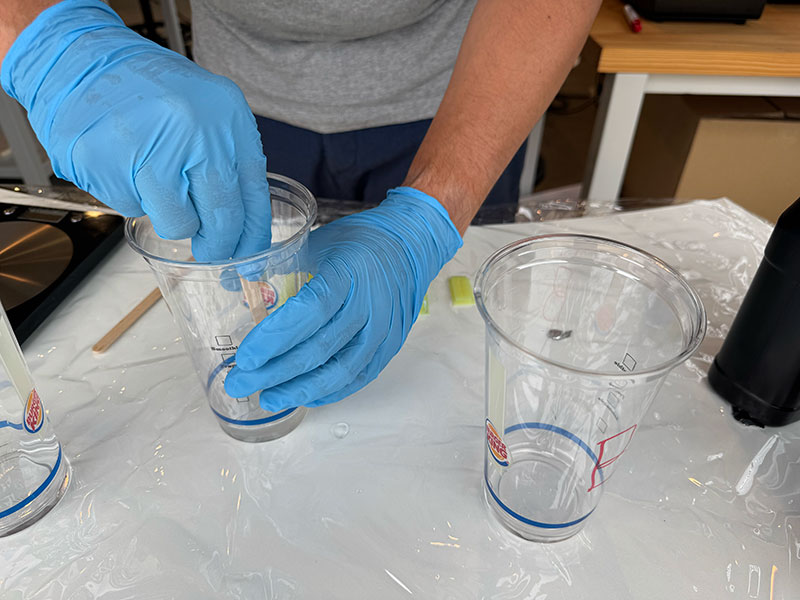
Once measured, both components were mixed quickly and homogeneously, since this type of resin usually has a limited working time.
Finally, I poured the mixture into the silicone molds, making sure to fully cover the geometry before the hardening process began.
This is the result
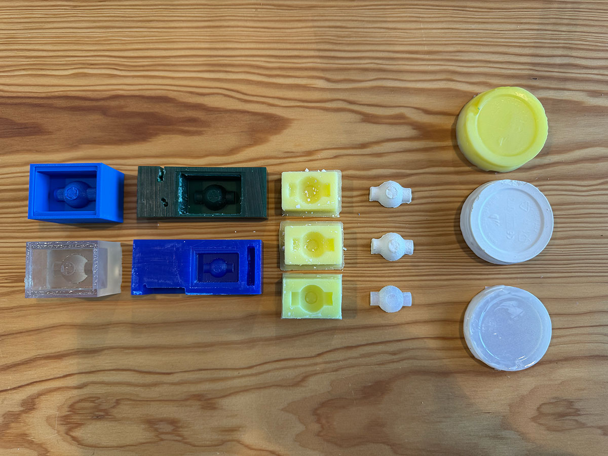
Family photo
This “family photo” brings together the full workflow developed during the week: from the wax molds and 3D printed molds, to the silicone negatives and the different casting tests. It visually summarizes the entire process, including both successful results and experimental iterations that were key to understanding the behavior of each material and technique.
Food safe
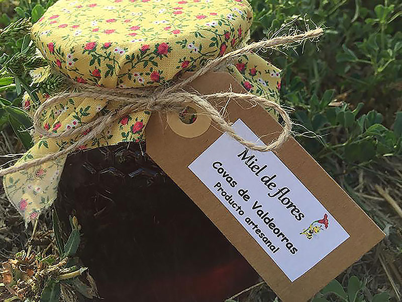
My intention for this workflow was to explore a food-safe molding and casting process, with the final goal of producing chocolate pieces. Due to time constraints, I was not able to complete the full process up to the final casting stage. However, I focused on developing a safe starting point by creating my own 100% natural beeswax mold, ensuring that the base material is suitable for future food-related applications.
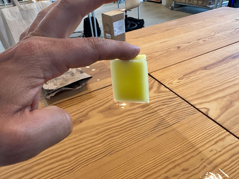
Beeswax preparation
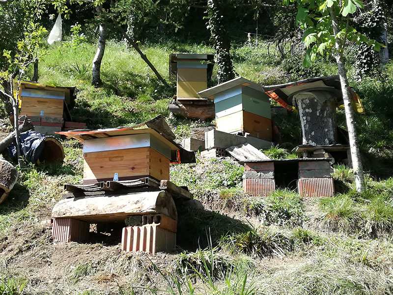
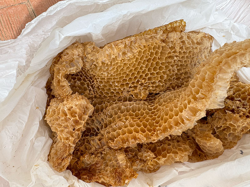
In this process, I worked with natural beeswax, using honeycomb directly sourced from my father-in-law’s beehives. This gives the material a very hands-on and experimental character.
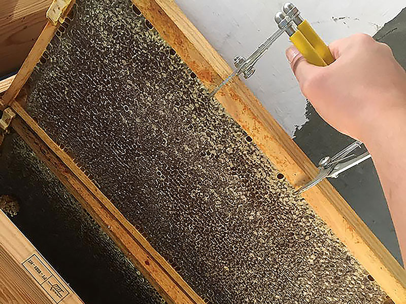
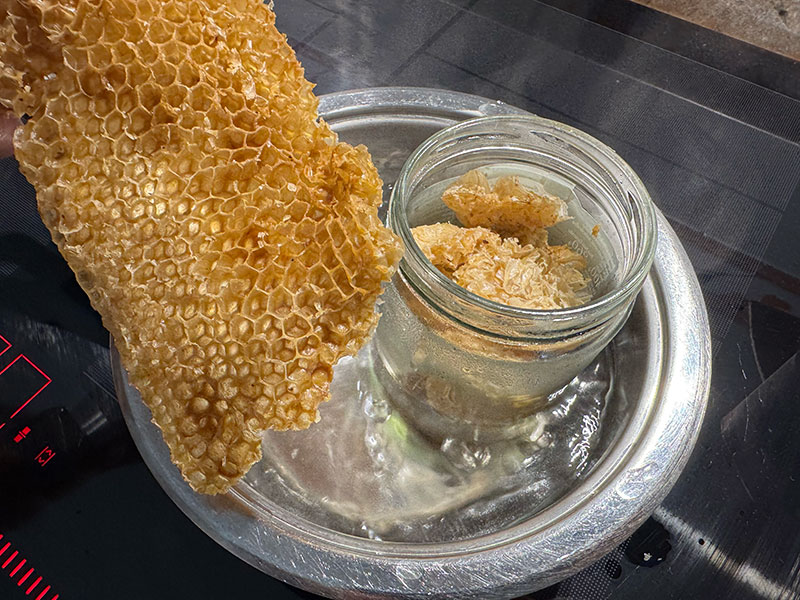
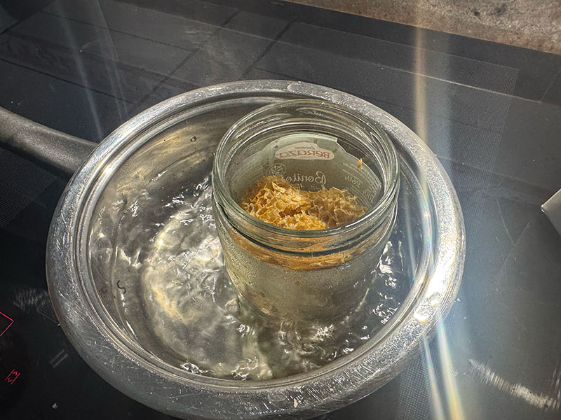
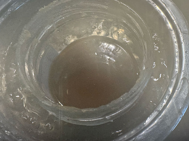
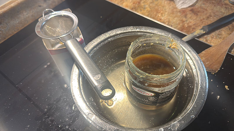
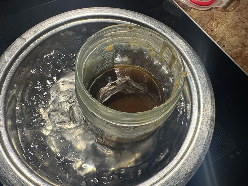
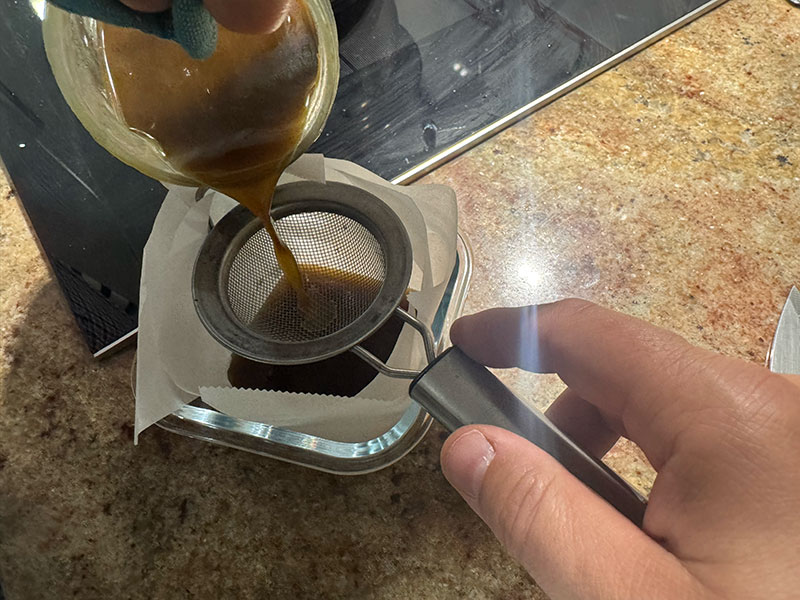
The first step was to melt the wax using a bain-marie method, placing small pieces of honeycomb inside a glass jar. This approach allows for a slow and controlled heating process, avoiding material degradation. As the wax melts, the natural impurities present in the honeycomb become visible.
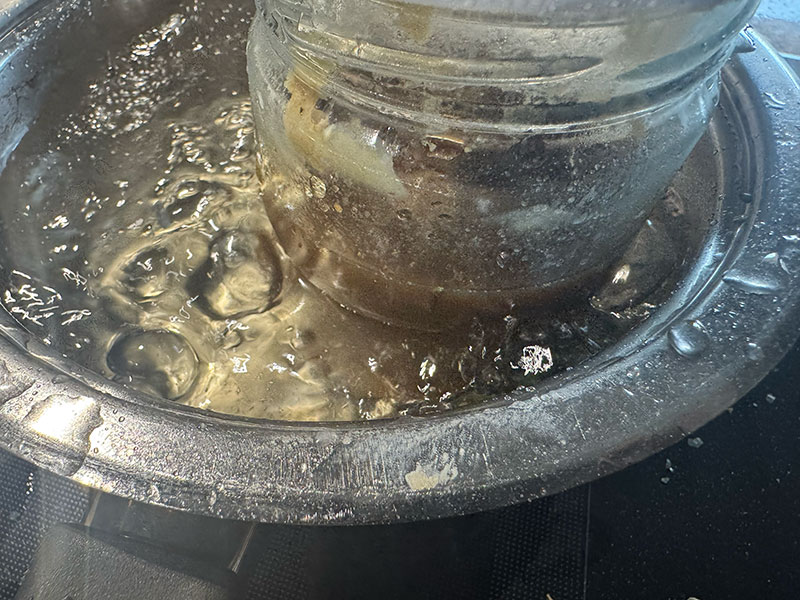
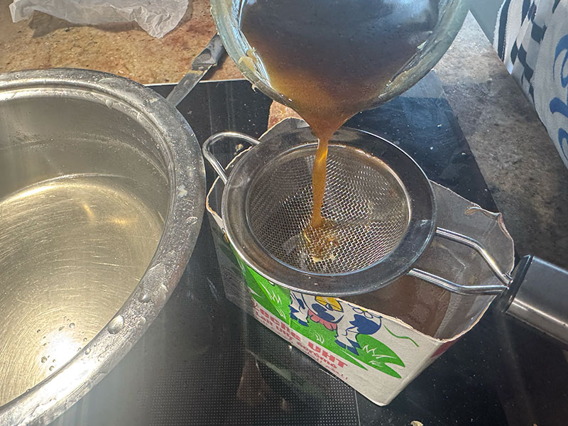
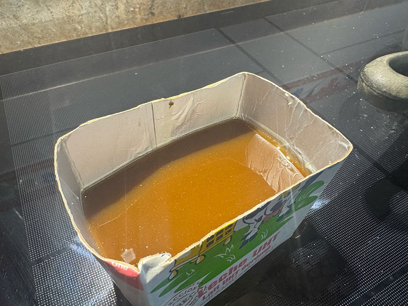
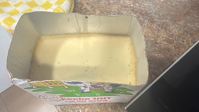
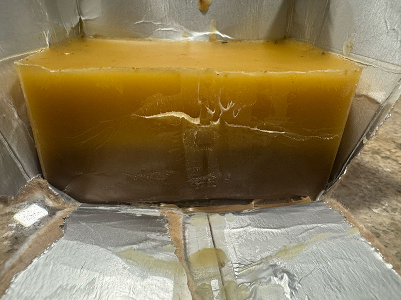
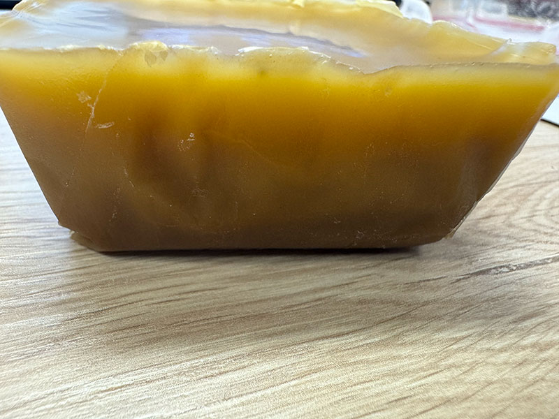
Once fully liquid, I proceeded to filter the wax to remove solid residues. Then, I poured the cleaned wax into an improvised mold, using the base of a milk tetra pak container, a simple but effective solution for this first test.
During the cooling process, which takes several hours, an interesting behavior can be observed: the wax transitions from a darker tone in its liquid state to lighter shades as it solidifies. Once fully cooled, the block shows very few impurities (mostly concentrated at the base, which can be easily removed). However, two slightly different tones are visible, likely due to incomplete mixing during the melting stage.
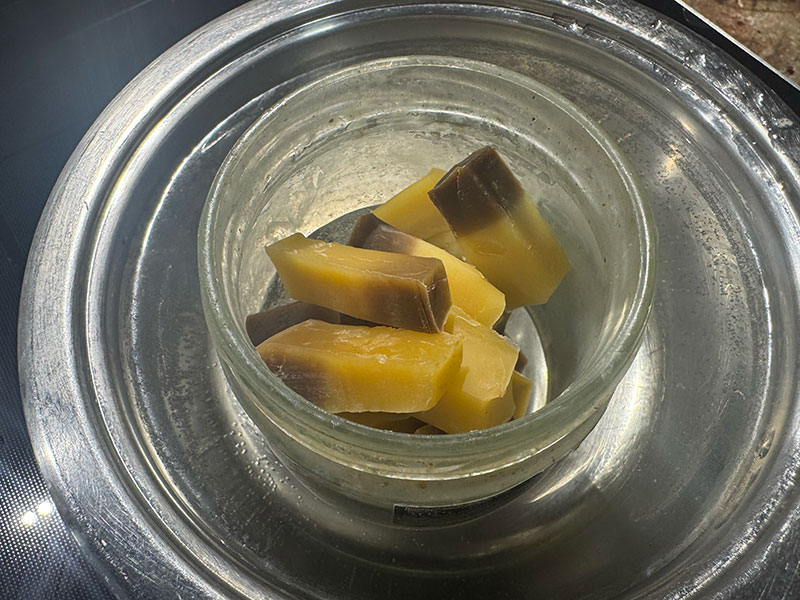
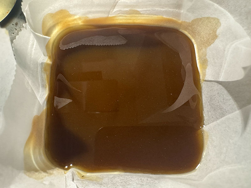
To improve this result, I repeated the process. I melted the wax block again, this time cutting it into smaller pieces to achieve a more homogeneous melting. After filtering again, I poured the wax into a glass container with baking paper.
In this second iteration, the previous tones blend better, resulting in a more uniform color. However, the final wax appears noticeably darker, most likely due to the additional heating cycle.
Finally, I decided not to repeat the process further and to use this block as the base material for the next steps.
To be continued...
Original code files for this documentation
Files for download
- 3D FreeCAD mold desing (03MoldeBENI.FCStd) FCStd · 512 Kb
- 3D .stl mold desing (03MoldeBENI.stl) STL · 5.5 Mb
- Mods rough toolpath (03MoldeBENI_mesh_slice_raster.rml) RML · 63 Kb
- Mods finish toolpath (03MoldeBENI_mill_raster_3D.rml) RML · 504 Kb
Final project development
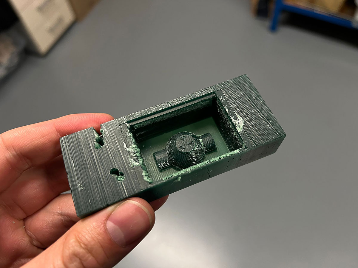
Although the main topic of this week was different, I also used the milling time of the wax block to move forward with some parts of the design of the box for my final project.
Final project development - Week14 sectionWeek questions/tasks
Final reflection
This week has definitely been one of the most intense and demanding so far. Although the initial goal seemed clear — designing a mold and producing parts through casting — the real process was full of unexpected issues that made the workflow much more complex.
The main challenge was the malfunctioning of the Roland SRM-20, a completely new machine that, instead of making the process easier, became a constant blocker. The spindle power and stability problems made it impossible to complete the milling process, forcing us to spend a significant amount of time testing, adjusting, and troubleshooting without success.
This situation affected the entire planning of the week and pushed us to look for alternative solutions, such as the backup mold milled at FabLab León, which involved waiting time, and the setup of the Lunyee CNC, which required configuration and full calibration before it could be used properly.
From a process point of view, going through the complete workflow — from creating the positive mold, to making the silicone negative mold, and finally producing the first castings — helped me understand in a very practical way the relationship between materials, techniques, and working conditions.
One of the most relevant lessons was seeing how apparently small factors, such as the base material of the mold (resin vs. wax), can completely affect the final result, especially in the case of silicone curing.
Despite all the difficulties, this week has been very valuable. Not only because of the final results, but also because of everything learned through real problem-solving, adapting to unexpected situations, and finding alternative ways to keep the process moving forward.
Without a doubt, it has been a tough week, but also one of the most meaningful in terms of practical learning.
Credits
I would like to thank the instructors Nuria ↗️, Pablo ↗️, and Adrián ↗️ for their guidance and support throughout this assignment.
Also thanks to Javier ↗️ (FabLab Ponferrada Manager) for facilitating our access to the fablab and lend us material.
And to my wife, for her help in recording the videos.
All texts were written in Spanish and translated into English using Google Translate and ChatGPT.