Week 5
3D Scanning and Printing
Contents
Week questions/tasks
Starting Point
My previous experience with 3D printing was minimal. I had bought a few 3D printed products, but mostly I had downloaded some free .stl files of things I needed and given them to a friend to print on his 3D printer.
Group assignment
We have decided for the group assignment that each of us will specifically document one of the 3D printers that we have available in the FabLab.
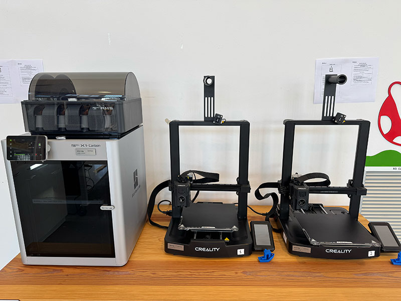
At FabLab Ponferrada we have 3 3D printers. 2 of them use filament and one uses resin:
- Bambu Lab X1 Carbon
- Creality Ender-3 V3 KE (2 units)
- Creality Halot 8K Mage Pro
Characteristics of 3D Lab printer(s)
Fablab Ponferrada 3D printers comparative table of specifications
Comparative table of specifications
| Spec | Bambu Lab X1 Carbon | Creality Ender-3 V3 KE | Creality Halot 8K Mage Pro |
|---|---|---|---|
| Technology | FDM (filament) | FDM (filament) | MSLA (resin) |
| Build volume | 256 × 256 × 256 mm | 220 × 220 × 240 mm | 228 × 128 × 230 mm |
| Layer height (min.) | 0.05 mm | 0.10 mm | 0.01 mm (10 µm) |
| Max speed | 500 mm/s | 500 mm/s | — (exposure-based) |
| Max acceleration | 20,000 mm/s² | 8,000 mm/s² | — |
| Standard nozzle | 0.4 mm (swappable) | 0.4 mm | — |
| Bed leveling | Automatic (LiDAR + sensors) | Automatic (CR-Touch) | Assisted manual leveling |
| Extrusion system | Direct Drive, hardened steel | Direct Drive | — |
| Compatible materials | PLA, ABS, PETG, TPU, Nylon, PC, CF, etc. | PLA, PETG, TPU, ABS | 405 nm UV resins |
| Heated bed | Yes (up to 120°C) | Yes (up to 100°C) | Not applicable |
| Enclosed chamber | Yes | No | Yes (with built-in air purifier) |
| Display | 5" touchscreen | 4.3" touchscreen | 4.3" touchscreen |
| Connectivity | Wi-Fi, LAN, microSD | Wi-Fi, USB | Wi-Fi, USB |
| Built-in camera | Yes | No | No |
| Approx. price range | High-end | Mid / budget | Mid-range |
| Best for | Engineering, advanced prototyping | Hobby, education, basic prototyping | Miniatures, high-detail parts |
Design rules for your 3D printer(s)
As I mentioned before, for this group assignment we've divided up so that each of us will document one of the printers. In this case, I'm going to do the Bambu and the resin Halot 8K.
In this case, I've decided to create a separates pages for the printers to simplify this documentation page and that it can be easily linked directly:
Specific design rules for: Bambu Lab X1 Carbon - Beni's documentation
Specific design rules for: Creality Halot 8K Mage Pro - Beni's documentation
Individual assignment
Design, document and 3D print an object (small, few cm3, limited by printer time) that could not be easily made subtractively
In this part I've decided to make two 3D objects en FreeCAD: a tube from which I've removed the filling of a internal sphere, and a hinge as unique objet.
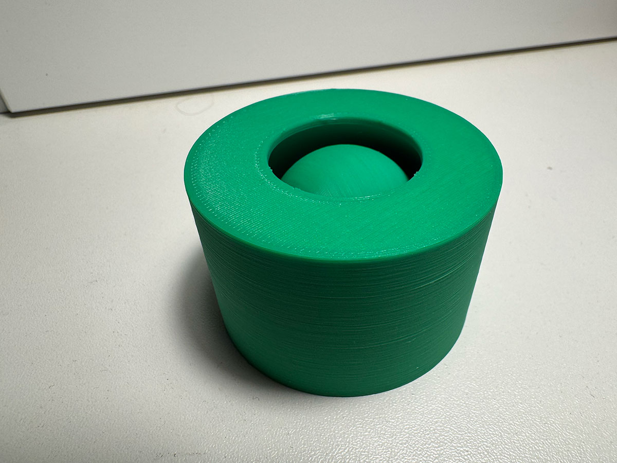
Tube-Sphere design
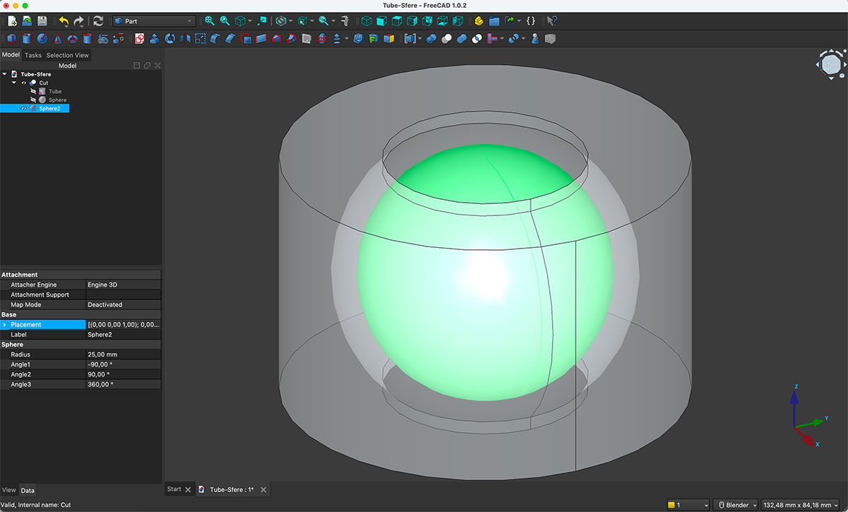
For this first exercise, I wanted to design a part that could not be easily manufactured using subtractive methods. The idea was simple: a tube with a completely hollowed sphere inside it.
I started in FreeCAD using the Tube tool. I defined a pipe 80 mm long, with an outer radius of 60 mm and an inner radius of 20 mm. This gave me the base geometry.
Then I created a sphere with a 40 mm radius and moved it inside the tube, making sure it was fully contained within the volume.
Once both solids were positioned, I selected them and applied the boolean “Cut” operation. This subtracts the sphere from the tube’s volume.
Finally, I created a 25mm inner sphere that is not in contact with the interior and cannot be removed through the cylinder's opening. In this way, I created two parts in a single piece, one inside the other.
The result is a tube with a fully enclosed spherical cavity inside it with another sphere inside — a geometry that would be practically impossible to manufacture using traditional machining, since there would be no way to access the interior to remove that material.
You can download the original design files in the downloads section at the bottom of this page
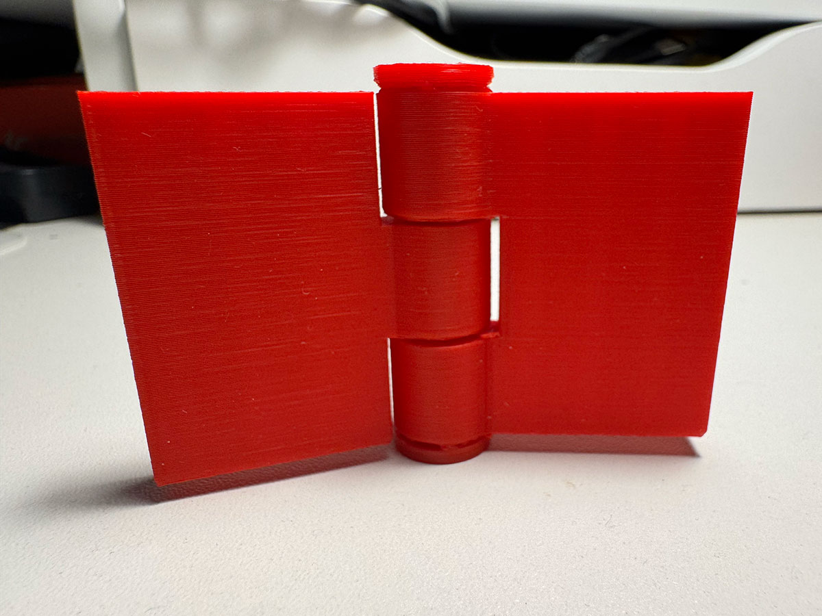
Hinge design
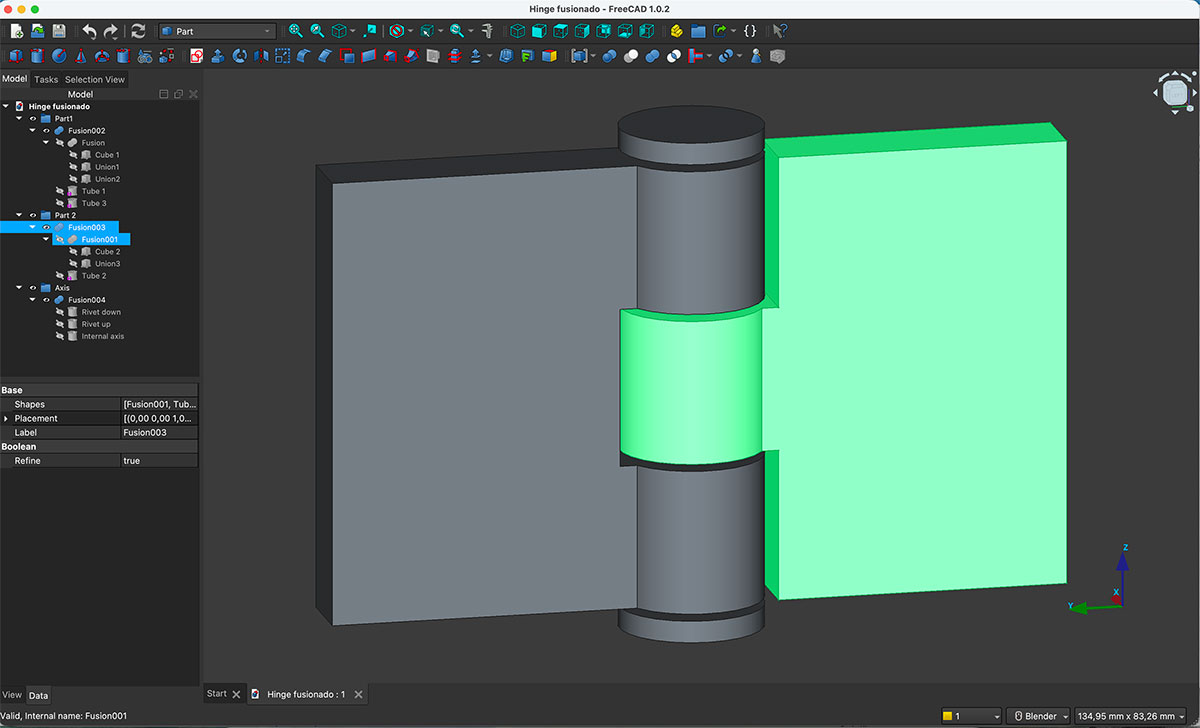
The second object I designed was a fully functional hinge printed as a single piece.
In FreeCAD, I conceptually divided the design into three parts: the left side, the right side, and the central axis.
For the two main sides, I started by creating blocks measuring 40 mm wide, 62 mm high, and 10 mm deep. To each of them, I fused hollow cylinders (tubes) 20 mm long, with an outer radius of 10 mm and an inner radius of 5 mm.
The left side has two tubes (one at the top and one at the bottom), while the right side has a single central tube. This alternating configuration allows both sides to interlock.
To ensure proper movement, I added a small clearance between the parts. I used a spacer block measuring 10 mm wide, 20 mm high, and 10 mm deep, which guarantees enough tolerance for the hinge to rotate freely without getting stuck.
All unions were made using the boolean “Union” operation, consolidating each side into a single solid piece.
The axis that passes through the tubes is a cylinder with a 4.5 mm radius and 66 mm length. To prevent it from slipping out, I added two additional cylinders at both ends, each with a 10 mm radius and 3 mm height. This way, the axis remains locked inside the assembly.
You can download the original design files in the downloads section at the bottom of this page
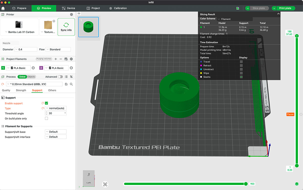
Tube-Sphere printing
For printing, I only needed internal supports for the inner sphere—a base in this case. Inside the tube, the printer has to handle the internal overhangs by creating bridges, something only possible with additive manufacturing. Also, the inner sphere doesn't fit through the tube's opening.
The goal of this piece wasn't aesthetics, but rather to clearly demonstrate a limitation of subtractive processes compared to 3D printing.
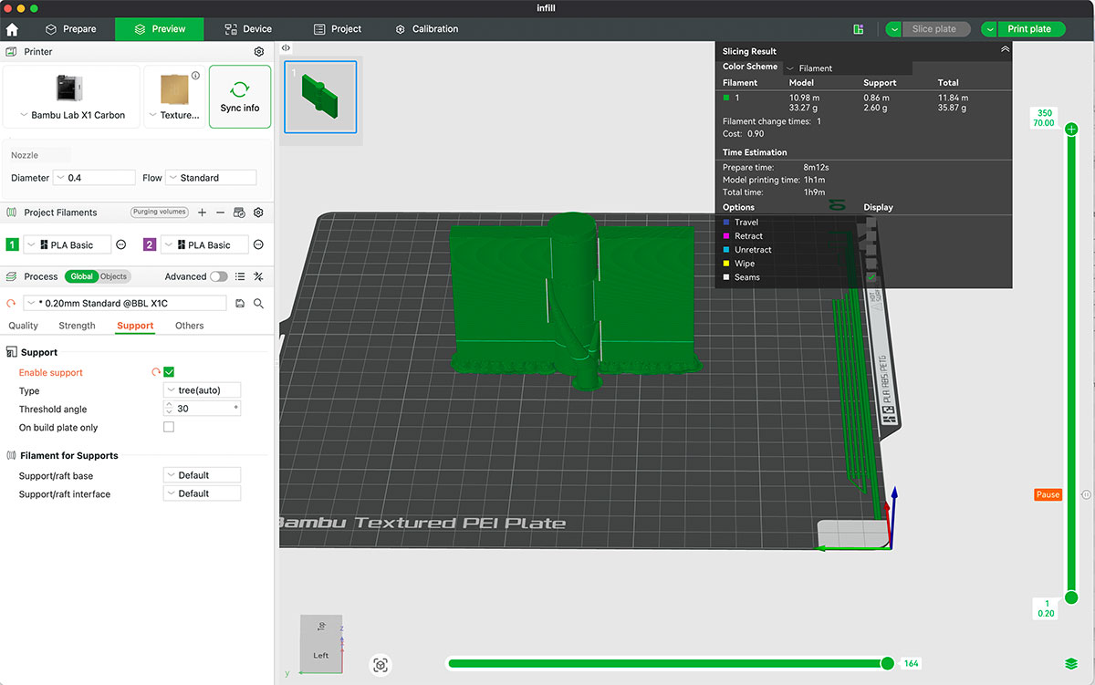
Hinge printing
The key aspect of this hinge is that it is printed as a single assembled object. No post-print assembly is required.
This type of part clearly demonstrates the potential of 3D printing to fabricate articulated mechanisms directly in one print — something that, using subtractive manufacturing, would require producing multiple separate parts and assembling them afterward.
After printing, the hinge works correctly thanks to the tolerances I left between the components. It was particularly interesting to observe how small adjustments in clearance directly affect the final mobility of the mechanism.
High quality video available on my YouTube channel ↗️.
- Layer height: 0,2 mm
- Strengthe walls: 2
- Infill: Grid 15%
3D scan an object (and optionally print it)
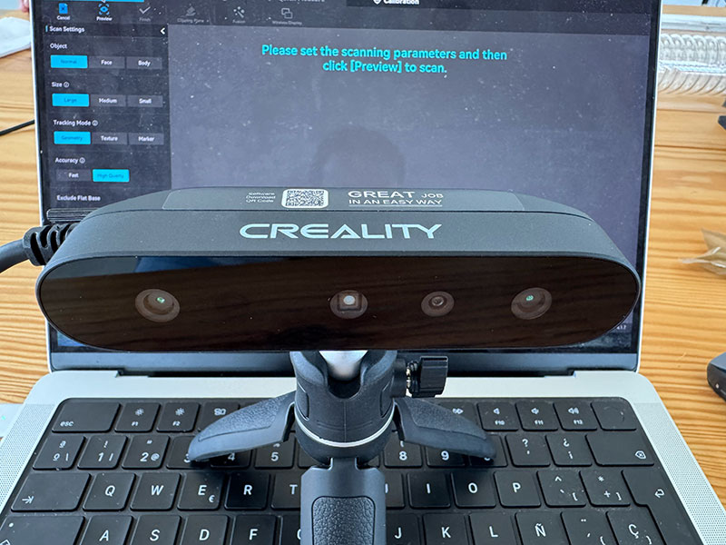
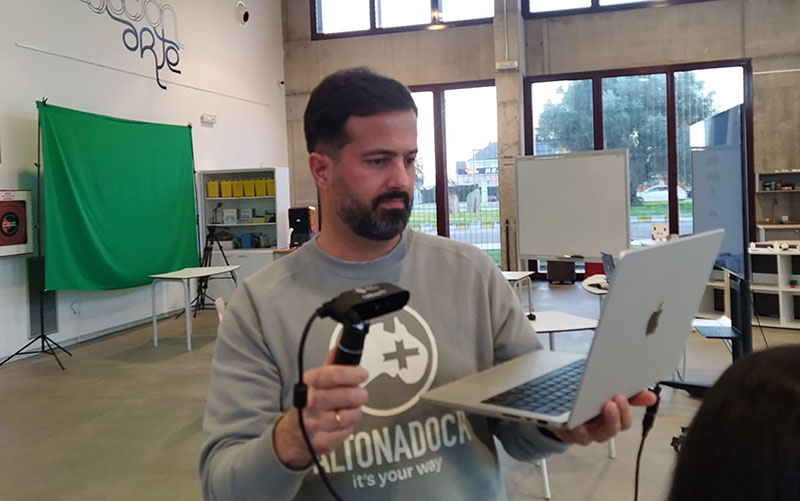
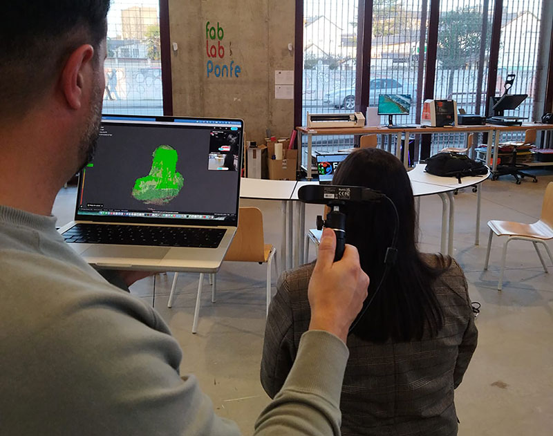
For this scan I used the Creality CR-Scan Ferret SE (available at the FabLab) with the Creality Scan app. My goal was simple: capture my wife’s bust and then 3D print it, so I focused on getting a clean and stable result.
CR-Scan Ferret SE — Specifications
| Feature | Specification |
|---|---|
| Model | Creality CR-Scan Ferret SE |
| Accuracy | Up to 0.1 mm |
| Resolution / Point Distance | 0.16 mm |
| Working Distance | 150–700 mm |
| Frame Rate / Scanning Speed | Up to 30 fps |
| Single Capture Range | 560 × 820 mm @ 700 mm |
| Minimum Scanning Volume | 50 × 50 × 50 mm |
| Outdoor Scanning | Supports scanning in bright sunlight |
| Color Texture | Supported (RGB color camera / color texture capture) |
| Light Source | NIR |
| Tracking Mode | Visual tracking |
| Alignment Methods | Feature / Marker / Color |
| Output Formats | OBJ / STL / PLY |
| Connection | USB Type-C (USB 3.0 / 2.0) |
| Compatible Systems | Windows, macOS, Android (note: iOS is listed for Ferret Pro) |
| Device Size | 120 × 30 × 26 mm |
| Weight | 105 g |
Setup
First I chose a spot with fairly even lighting and avoided direct sunlight. My wife sat down in a comfortable position so she could stay still during the scan. She didn’t tie her hair back, so I already expected the hair area to be trickier and possibly need some cleanup later.
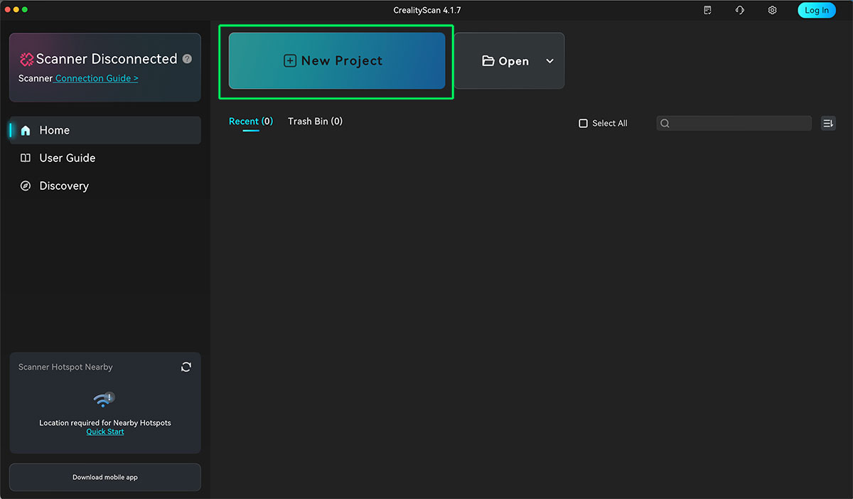
Then I connected the scanner to my computer, opened Creality Scan, and started a new project.
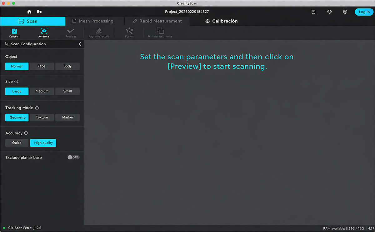
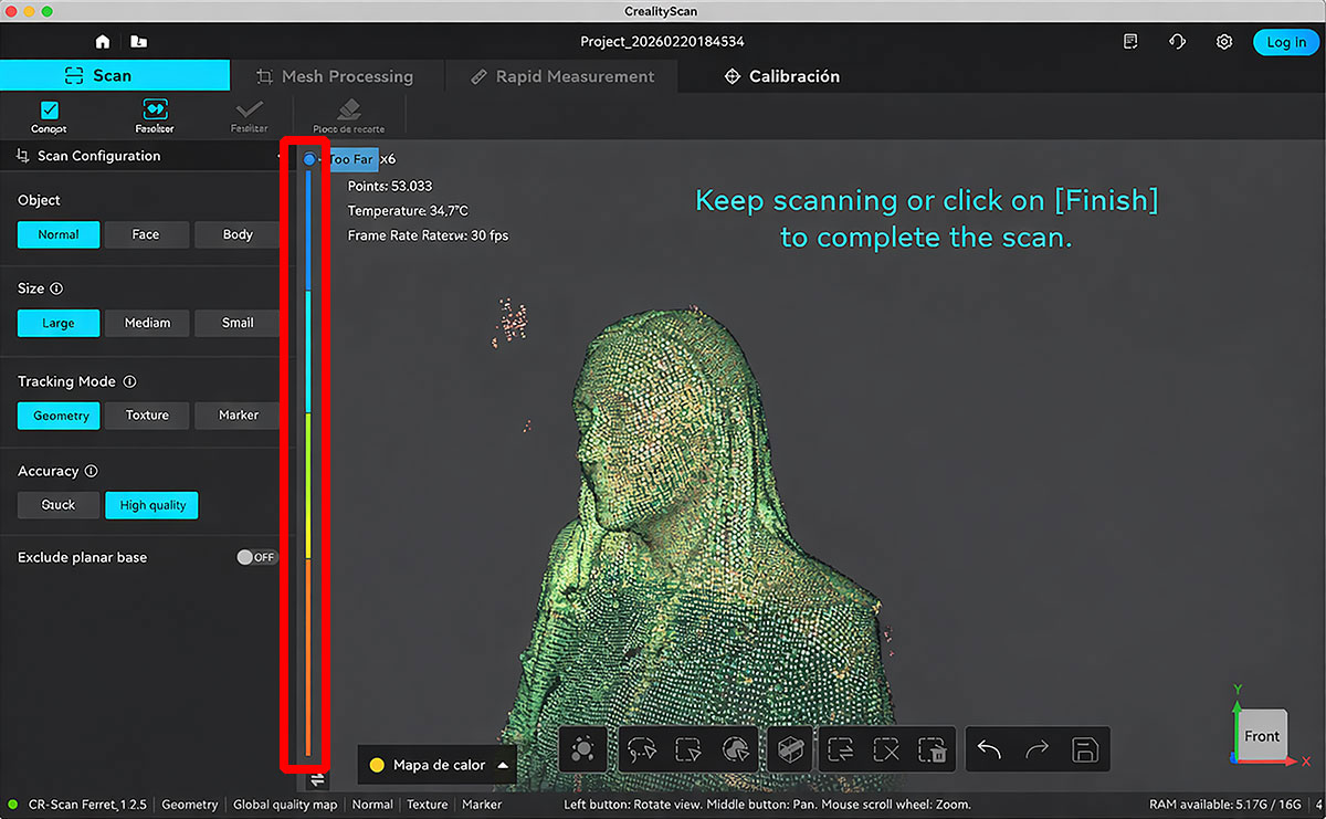
Scan settings in Creality Scan
These are the settings I used:
- Object type: Normal object
- Object size: Large
- Tracking mode: Geometry tracking
- Accuracy: High quality
Scanning
I started scanning from the front of the bust and moved the scanner slowly and smoothly, without sudden motions. One thing I really liked is that I could see the scan building up live on the screen while I was moving around.
The app also gives you quick visual feedback with colors: green usually means the area is being captured well, and red warns you that the quality is worse or that the scan needs more data. That helped me decide where to go back and rescan.
On the side of the interface there’s a vertical bar that was super useful. It helped me spot which areas were still “open” (not fully closed yet), and at the same time it guided my scanning distance, showing if I was scanning too close or too far away.
I kept moving around the bust, covering the sides and making sure there was enough overlap between what I had already captured and the new areas, so the tracking wouldn’t get lost. Sitting down made it easier to keep things steady, although the hair still created a few less-defined zones.
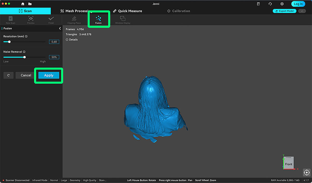
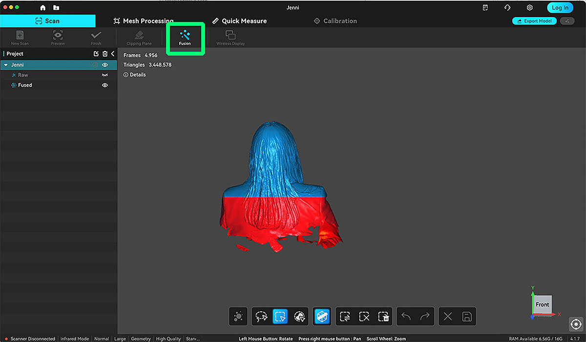
Fusion
After the scan, I ran the Fusion step. This is where the software merges everything I captured into a more consistent dataset, smoothing out transitions between passes before I move on to editing. I ran the Fusion option, where the software merges all the captured data into a more coherent and unified model.
After that, I applied a cut on the lower part of the model to remove the unnecessary bottom area and properly close the design. This allowed me to create a clean and flat base, which is essential if I want the bust to sit correctly on the print bed later.
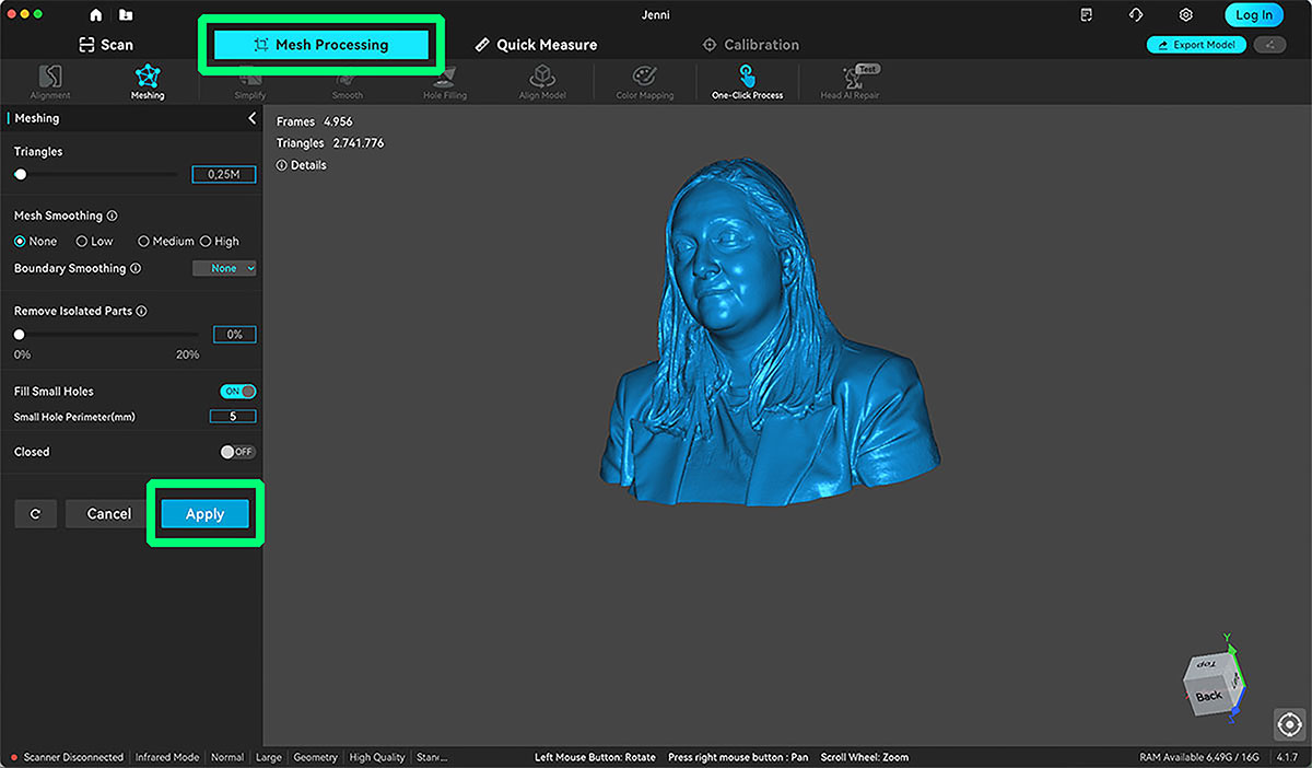
Meshing
In the Mesh Processing section, I applied a smooth mesh to slightly refine the surface without losing too much detail. I also reduced the number of triangles in the model. This makes the file lighter and easier to handle, without significantly affecting the visual quality. It’s a useful step before exporting and continuing the workflow.
Finally, I exported the model as an .STL file.
Cleanup
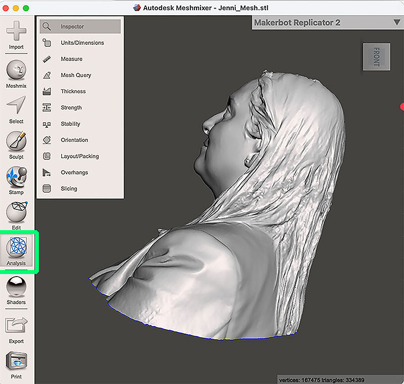
To complete the workflow, I downloaded and installed MeshMixer.
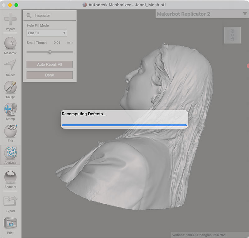
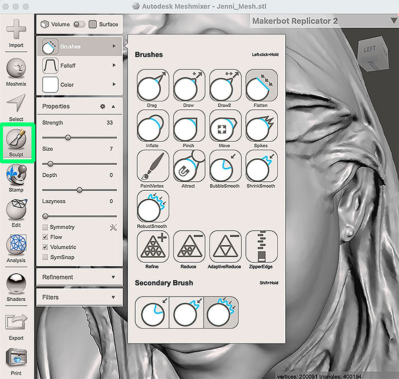
In this case, the model was already quite clean and well closed from Creality Scan, so it didn’t require major repairs. However, to explore the software a bit further, first I make a "Analysis" and later I used the “Sculpt” tool to fix a small imperfection on the top of the head.
It wasn’t strictly necessary, but it was a good opportunity to test how small manual adjustments can be made directly on the mesh.
Once I was satisfied with the result, I exported the model again as an .STL file, leaving it ready for the 3D printing stage, and this is look like:
This .stl file is not available for download due to its large size.
3D Print
I decide to print the scan on resin.
Before printing, I check the website of the manufacturer (Winkle) of the resin I am going to use to see its characteristics and safety recommendations.
Resin datasheet (spanish PDF): Winkle 3D Water-Washable 10K Resin
Winkle 3D Water-Washable 10K Resin specifications
| Specification | Details |
|---|---|
| Brand / Model | Winkle 3D Water-Washable 10K Resin |
| Type | Water-washable photopolymer resin |
| Color | Transparent |
| Quality | High Quality – 10K |
| UV Wavelength Range | 385 – 405 nm |
| Printer Compatibility | LCD / DLP (405 nm) |
| Density | 1.25 g/cm³ |
| Shore Hardness | 80 – 85 D |
| Elastic Modulus | 31.44 MPa |
| Flexural Modulus | 1091.45 MPa |
| Flexural Strength | 40.82 MPa |
| Bottom Exposure Time | 50 – 60 seconds |
| Normal Exposure Time | 3 – 5 seconds |
| Water Washable | Yes |
| Washing Time | 10 – 15 minutes |
| UV Curing Time | 10 – 20 minutes |
| Post-processing | Water wash + UV curing |
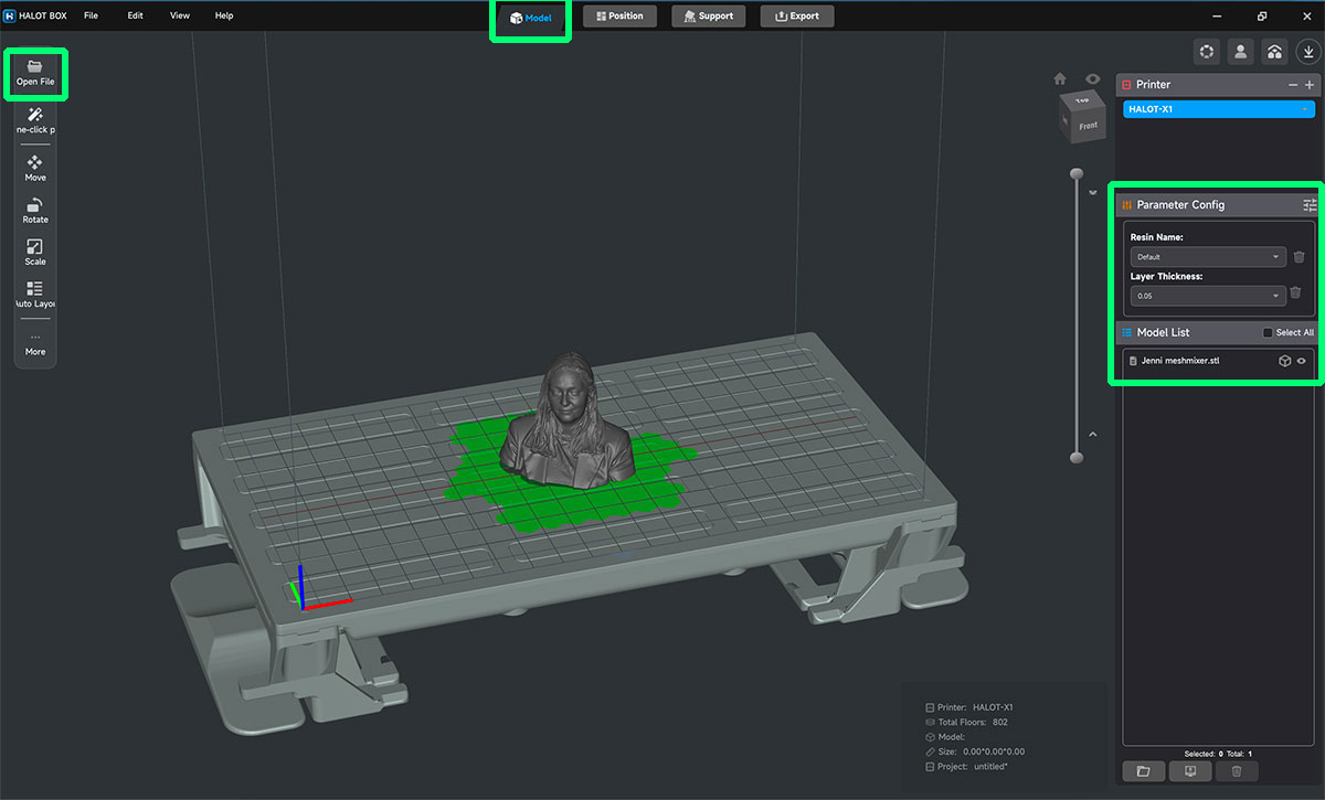
To prepare the print, I use Halot Box, the dedicated slicing software for the Creality HALOT-MAGE PRO 8K.
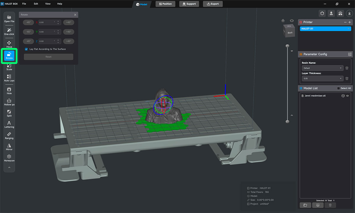
I import the STL file into HalotBox and the first thing I do is review the orientation. In resin printing this is especially important: it is not only about making the part “fit”, but about reducing suction forces between layers and avoiding unnecessary support marks on visible surfaces. In this case, the printing order is reversed compared to what is shown in HalotBox, so supports are not required.
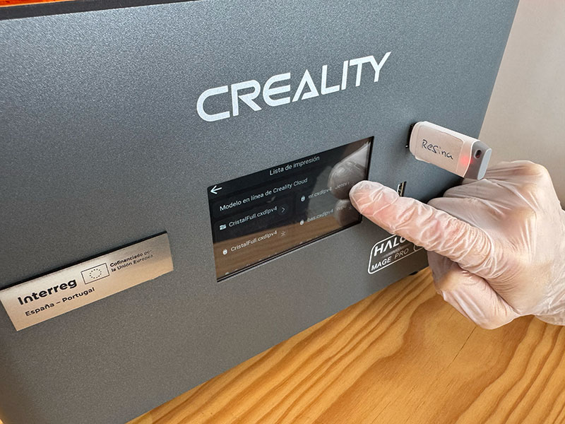
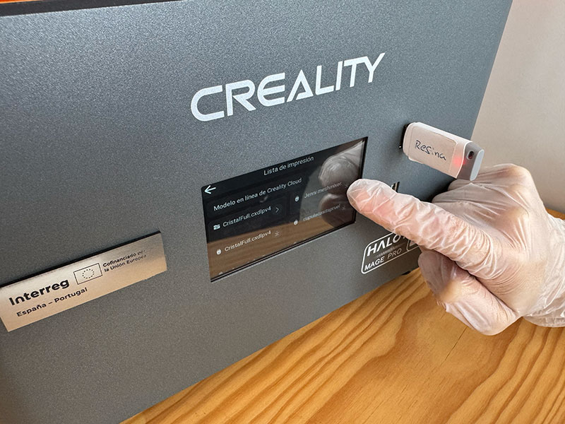
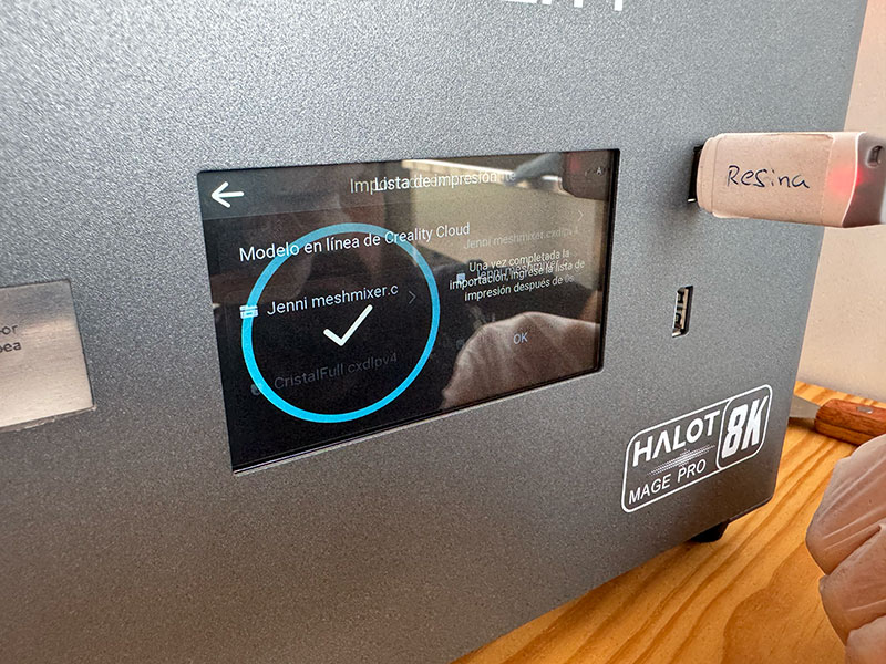
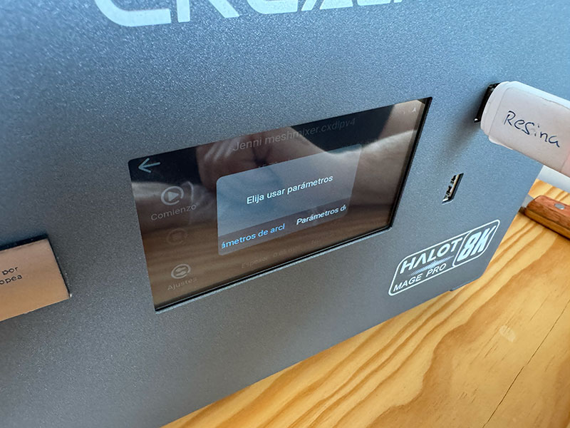
Next, I configure the exposure parameters according to the water-washable resin I am using: a bottom exposure of around 30 seconds to ensure proper adhesion to the build plate, and normal exposures of 1.5 seconds per layer, with a layer height of 0.05 mm to maintain good detail. Once the file is sliced, I export it to a USB drive and connect it directly to the printer.
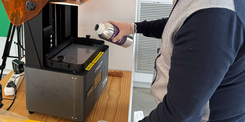
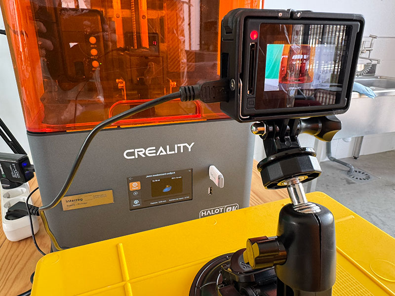
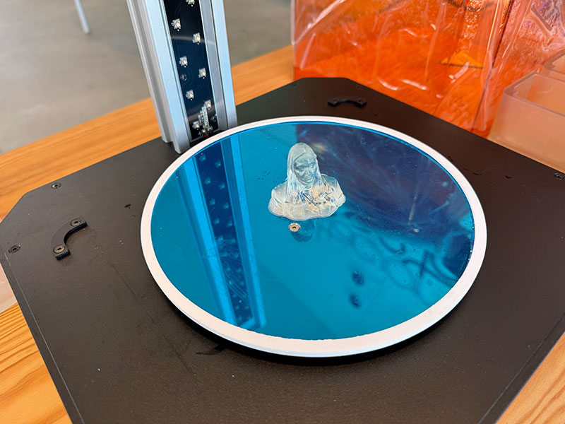
Before starting the print, I shake the resin bottle thoroughly to homogenize the material and pour it into the vat without exceeding the maximum indicated level. I launch the job from the HALOT-MAGE PRO 8K touchscreen and closely monitor the first layers. If the base adheres correctly to the build plate, the rest of the process usually runs smoothly.
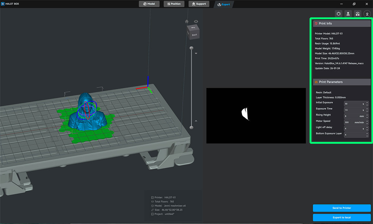
- Layer thickness: 0,5 mm
- Exposure time: 1,5 seconds
- Rissing height: 8 mm
Last seconds video
High quality video available on my YouTube channel ↗️.
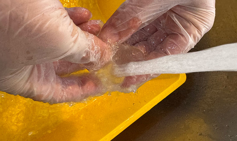
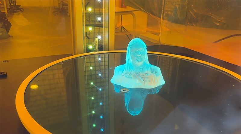
When the print is finished, I let the part drip for a few minutes so the excess resin can flow back into the vat. I remove the build plate and, wearing gloves, carefully detach the part. At this stage the piece is still covered with uncured resin, so it goes directly to the washing process.
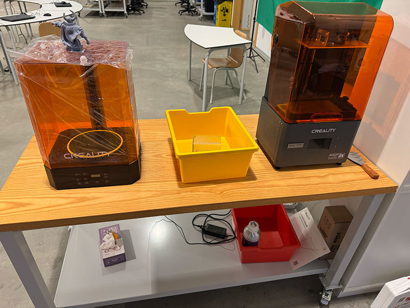
Resin wash
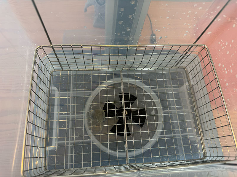
For this step, I use the Creality UW-03 Washing/Curing Machine. Since I am working with water-washable resin, I fill the container with clean water and place the part inside. I activate the washing cycle for approximately 10–15 minutes. The agitation system allows the water to reach all details and cavities, removing any remaining liquid resin.
Wash video process
High quality video available on my YouTube channel ↗️.
Resin cure
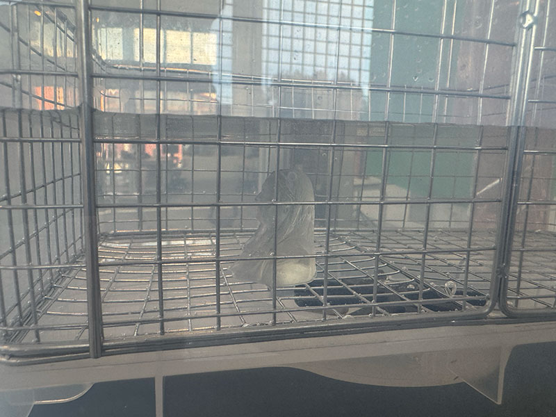
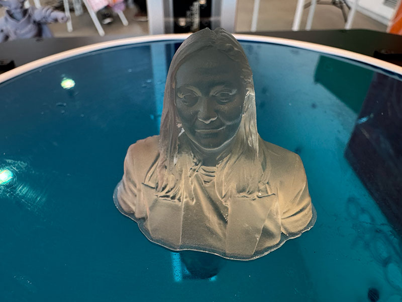
Once cleaned, I let the part dry completely before placing it back into the machine, this time in curing mode. I set between 10 and 20 minutes of UV exposure. During this process, the rotating platform ensures uniform light distribution, completing the material’s polymerization and providing its final hardness and dimensional stability.
Cure process video
High quality video available on my YouTube channel ↗️.
The result is a highly detailed part with smooth surfaces and very precise definition, characteristic of resin 3D printing.
Handflipper 3D print text my final project
As part of this week's activities, I print the handflipper designed on week 02 to begin to get acquainted with the necessary dimensions, thicknesses, and hardnesses.
Final project development - Week05 sectionOriginal code files for this documentation
Files for download
- Tube-Sfere (Tube-Sfere.FCStd) FCStd · 22 Kb
- Tube-Sfere (Tube-Sfere.3mf) 3mf · 65 Kb
- Tube-Sfere (Tube-Sfere.stl) STL · 339 Kb
- Hinge (Hinge_fusionado.FCStd) FCStd · 39 Kb
- Hinge (Hinge_fusionado.3mf) 3mf· 39 Kb
- Hinge (Hinge_fusionado.stl) STL · 666 Kb
Credits
All texts were written in Spanish and translated into English using Google Translate and ChatGPT.