Week 11
Networking and Communications
Contents
Starting Point
This week focuses on networking and communications, a topic that is deeply integrated into our daily lives. From mobile phones and Wi-Fi connections to smart home devices and industrial systems, we are constantly surrounded by technologies that depend on data exchange between devices. Even so, it is easy to take this connectivity for granted without really understanding what happens behind the scenes.
From a personal point of view, and thanks to my professional environment, I have already had some contact with communication systems and network-based technologies. This experience gives me a general idea of how devices can interact, exchange information, and coordinate actions. However, most of the time this has been from a higher-level perspective, using already implemented systems rather than building them myself.
For this week, my goal is to dive deeper into the fundamentals of communication between devices by implementing my own system. I am especially interested in understanding concepts like addressing, communication reliability, and how different protocols can be used depending on the needs.
Finally, I want to connect this learning with my final project, exploring how to integrate communication between nodes so that different parts of the system can work together in a coherent way. This feels like a natural next step after developing individual devices in previous weeks.
As I reviewed my current board design, I realized that I am working with some important connectivity limitations. My PCB already includes two LEDs and two buttons soldered to pins D3, D4 (SDA), D5 (SCL), and D6 (TX). This means that some of the pins normally used for communication protocols such as I2C and part of UART are already occupied, which makes wired communication much less flexible without redesigning the board.
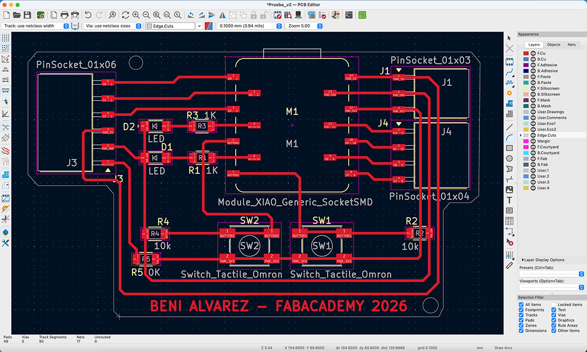


Until now, I have mainly been using the XIAO RP2040, which is a very practical microcontroller for many tasks, but it does not include built-in wireless connectivity. For a week focused on networking and communications, this becomes an important limitation.
One positive aspect of my design is that the PCB allows me to swap the microcontroller, so I can test different options without changing the whole board. I also have a XIAO ESP32-C6, which adds Wi-Fi and BLE connectivity. However, this does not completely solve the problem, because pins D4, D5, and D6 match the same connections used in the RP2040 version, so they are still occupied by the existing components on the PCB.
On top of that, designing and fabricating a new PCB is not an option right now, since the Roland SRM-20 in the Fab Lab is still under repair, as I already mentioned in week 8. Because of that, I have to move forward by adapting to the board I already have and making the most of its current constraints.
Firsts steps for XIAO ESP32 C6
Configuring Arduino IDE for XIAO ESP32-C6
As mentioned before, one of the advantages of my PCB design is that I can swap the XIAO microcontroller, moving from the RP2040, which I have been using so far, to the ESP32-C6, which includes wireless connectivity. This change is essential in order to properly approach this week’s networking assignments.
When starting to work with ESP32 microcontrollers, it is necessary to configure them in the development environment first. In my case, I followed the official Seeed Studio tutorial for the XIAO ESP32-C6 ↗️.
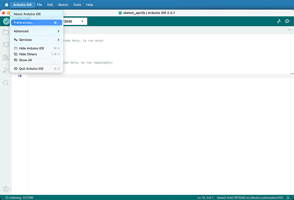
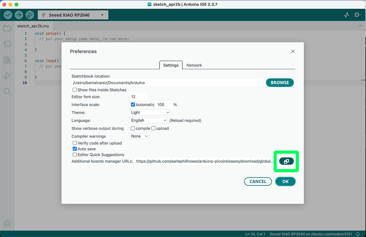
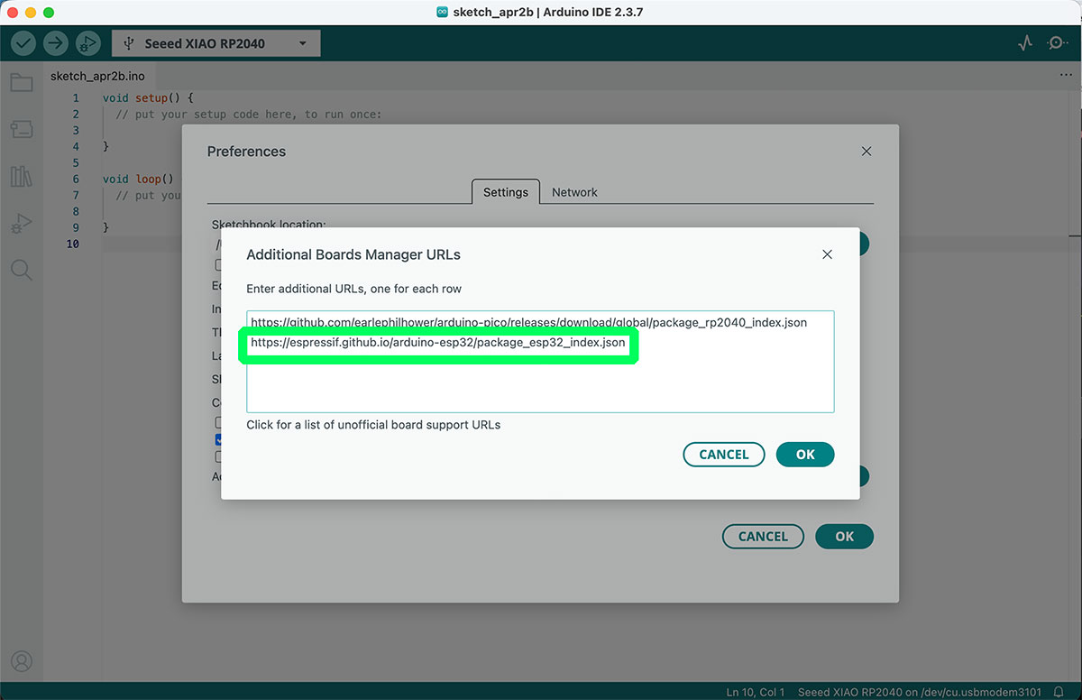
The process starts in the Arduino IDE, by going to Preferences. In the section “Additional Boards Manager URLs”, the following URL must be added:
https://espressif.github.io/arduino-esp32/package_esp32_index.jsonThis is added alongside the URL that was already configured for the RP2040.
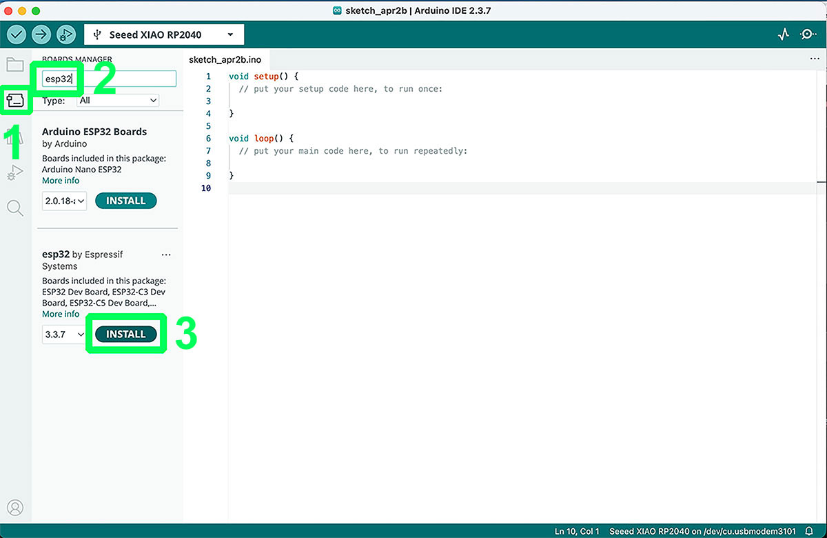
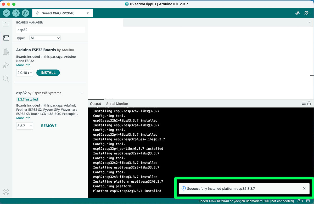
Once the URL is added, the next step is to open the Boards Manager, search for “ESP32”, and install the package “esp32 by Espressif Systems”. After this, the environment is ready to start programming the XIAO ESP32-C6 using Arduino.
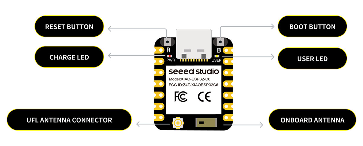
XIAO ESP32-C6 overview
For this week, I decided to work with the XIAO ESP32-C6, a compact microcontroller that feels much more suitable for networking tasks than the XIAO RP2040 I had been using before. The main reason is simple: it already includes built-in wireless connectivity, which opens the door to testing real communication between devices in a much more direct way.
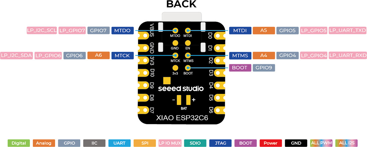
According to the official documentation, the XIAO ESP32-C6 is based on a 32-bit RISC-V single-core processor running at up to 160 MHz, and it integrates Wi-Fi 6, Bluetooth Low Energy 5.0, and support for Zigbee, Thread, and IEEE 802.15.4. This makes it especially interesting for IoT applications and for projects where several nodes need to communicate with each other.
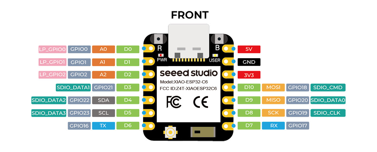
Another important point for me is that it keeps the same XIAO form factor, so I can physically use it on my existing PCB without redesigning the board. It also provides the usual communication interfaces such as UART, I2C, and SPI, together with multiple GPIOs and analog pins, which gives enough flexibility for experimentation even within the limitations of my current board design.
Overall, I see the XIAO ESP32-C6 as a very natural step forward for this week. It not only helps me explore wireless communication between nodes, but also connects much better with the direction of my final project, where communication between different parts of the system will likely play an important role.
Main features comparison ESP32-C6 Vs. RP2040
| Feature | XIAO ESP32-C6 | XIAO RP2040 |
|---|---|---|
| Processor | 32-bit RISC-V single-core, up to 160 MHz | Dual Cortex-M0+, up to 133 MHz |
| Wireless connectivity | Wi-Fi 6, BLE 5.0, Zigbee, Thread, IEEE 802.15.4 | No built-in wireless connectivity |
| SRAM | 512 KB | 264 KB |
| Flash memory | 4 MB | 2 MB |
| UART | 1x UART + 1x LP_UART | 1x UART |
| I2C | 1x I2C + 1x LP_I2C | 1x I2C |
| SPI | 1x SPI | 1x SPI |
| GPIO / PWM | 11 GPIO (PWM) | 11 digital pins (all PWM) |
| Analog inputs | 7 ADC | 4 analog pins |
| Form factor | XIAO compact format | XIAO compact format |
| USB connector | USB-C | USB-C |
| Best fit | Wireless communication, IoT, networking | General embedded development without wireless |
Group assignment
We have decided that, as a group effort, each of us will specifically document some of the tests performed on our page.
Send a message between two projects
Communication using Bluetooth Low Energy (BLE)
To fulfill the requirement of sending a message between two projects, I decided to use Bluetooth Low Energy (BLE) as the communication method, connecting a Seeed Studio XIAO ESP32-C6 board to a smartphone.
The idea is to configure the XIAO as a BLE server, allowing the phone to detect it, connect to it, and establish a data exchange channel. To achieve this, I followed the official Seeed Studio documentation, specifically the tutorial on Bluetooth usage with this board.
The first step was to properly configure the environment in the Arduino IDE, selecting the XIAO ESP32-C6 board and the correct port. Then, I worked with the required BLE libraries such as BLEDevice, BLEUtils, and BLEServer, which allow creating and managing the Bluetooth server.
The program uploaded to the microcontroller creates a BLE server that reads the state of the two buttons on my PCB and sends a message depending on which one is pressed. This results in a simple but effective communication between the hardware and an external device.
Arduino code · 01esp32_BTbuttons.ino Show code
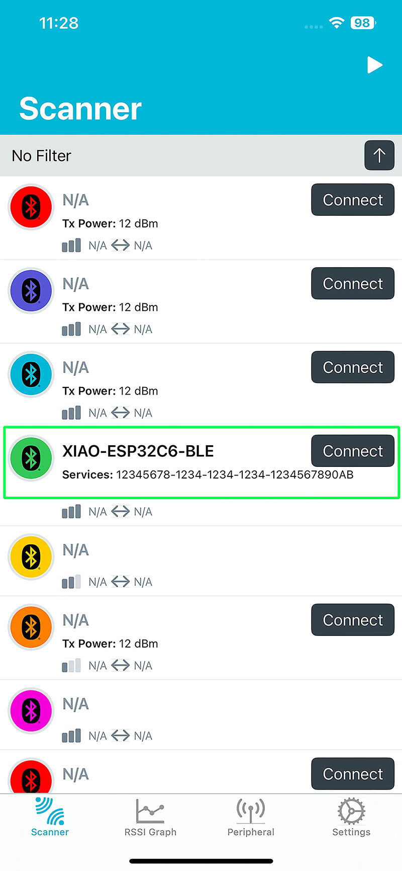
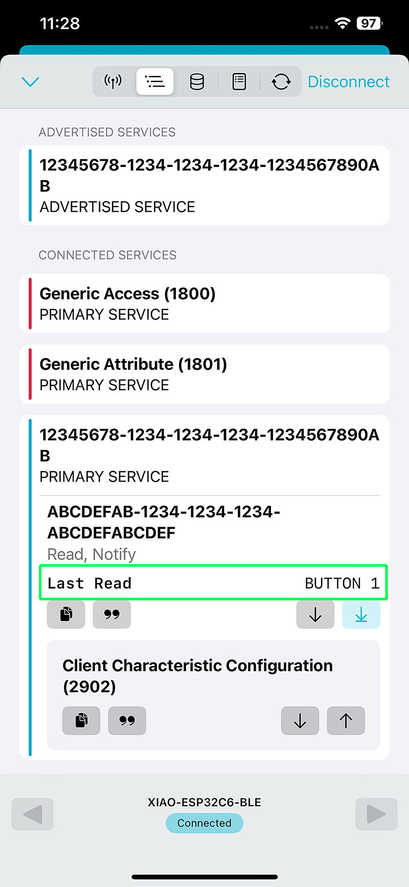
On the client side, I used an iPhone with the application nRF Connect for Mobile, which allows scanning and connecting to nearby BLE devices. Once the app is open, I search for a device named "XIAO-ESP32C6-BLE" and connect to it.
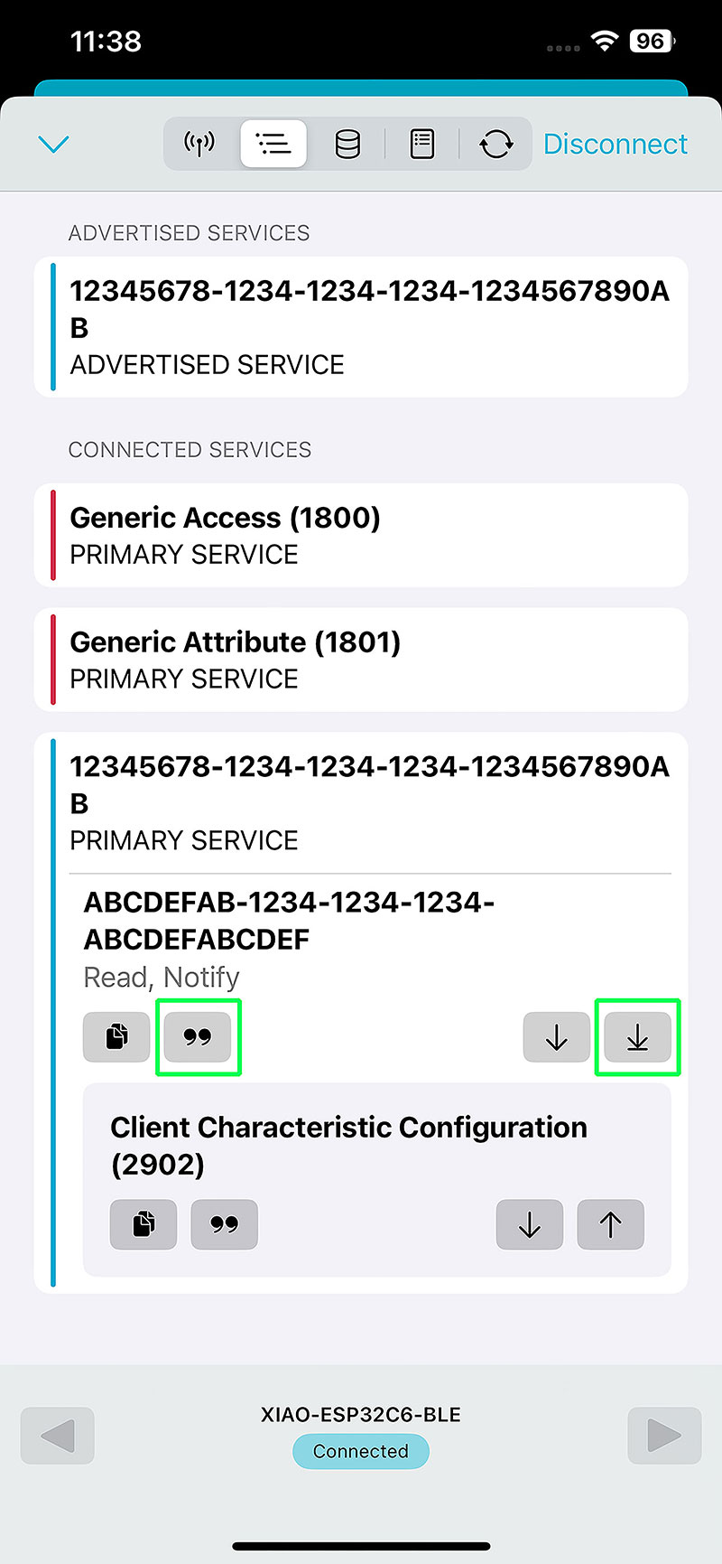
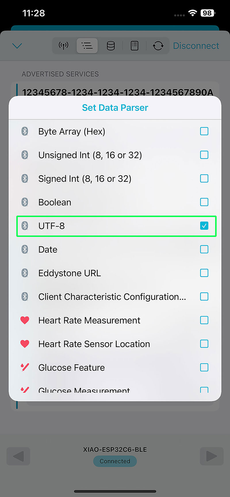
After connecting, the available BLE services are displayed. Inside them, I access the characteristic defined in the code using a custom UUID, which in my case is "abcdefab-1234-1234-1234-abcdefabcdef". By enabling data reading and setting the parser to UTF-8, I can visualize the messages sent by the board.
High quality video available on my YouTube channel ↗️.
The result is immediate: every time I press one of the buttons, the corresponding message appears in the app, such as "BUTTON 1" or "BUTTON 2", confirming that the communication works correctly.

Communication using Wi-Fi
After testing communication with Bluetooth Low Energy, the next step was to explore a more direct and visual approach: communication using Wi-Fi.
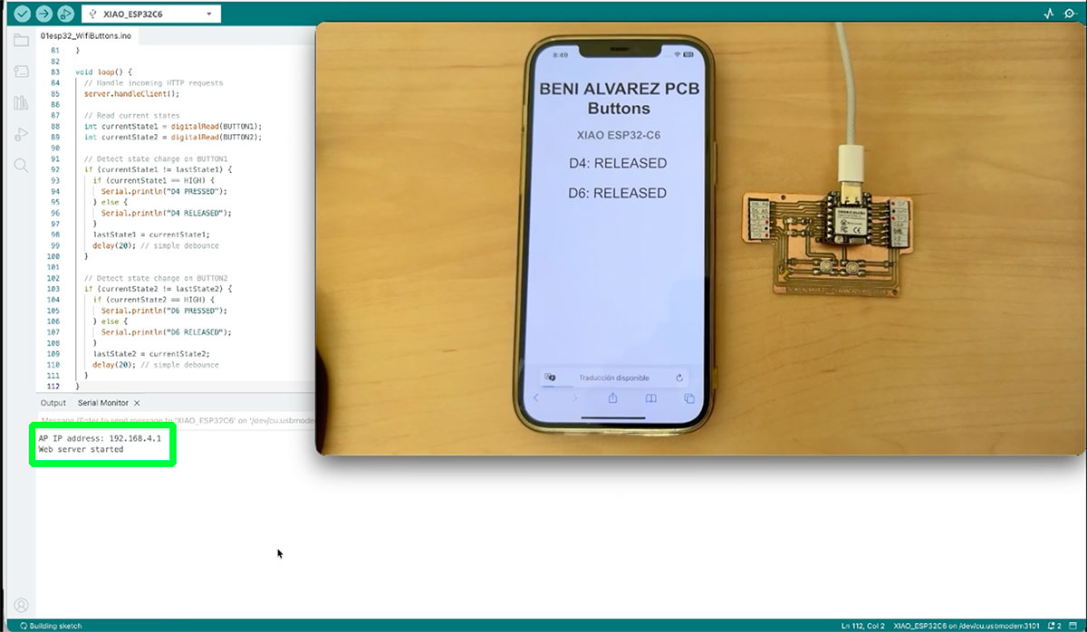
For this, I developed an Arduino sketch that turns the XIAO ESP32-C6 into a Wi-Fi access point and, at the same time, a web server. This means the board creates its own wireless network, allowing me to connect directly from a smartphone or computer without relying on an external network.
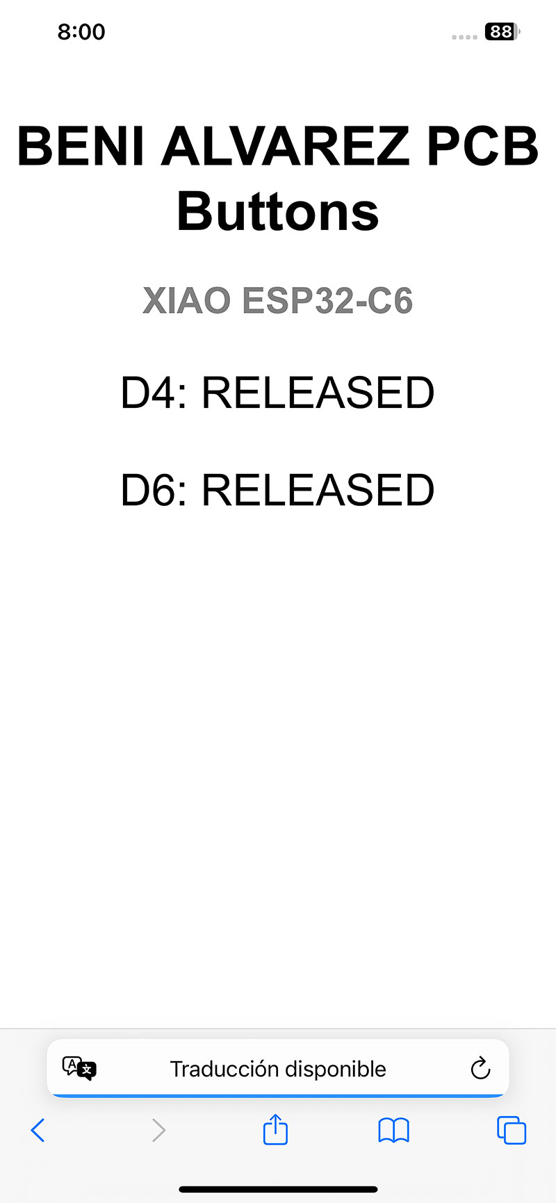
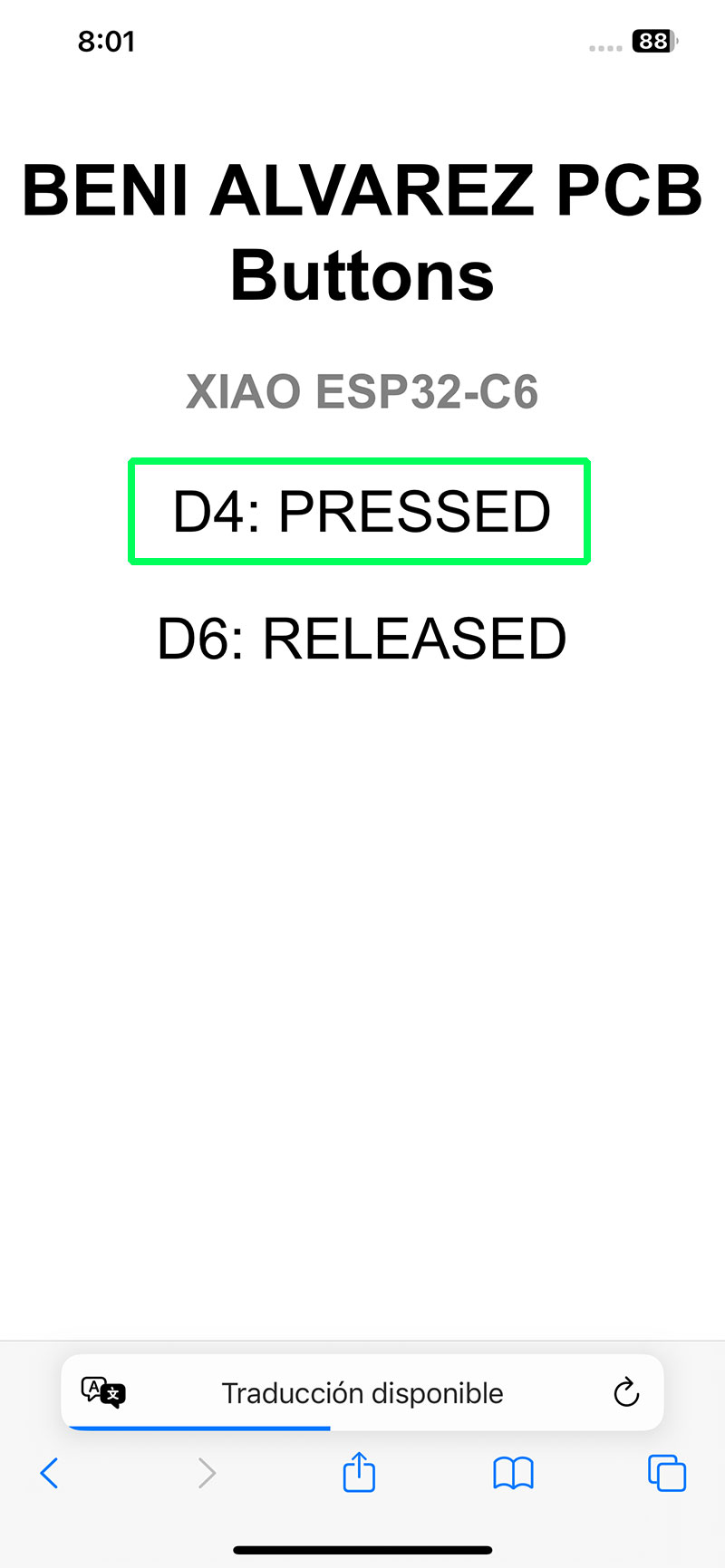
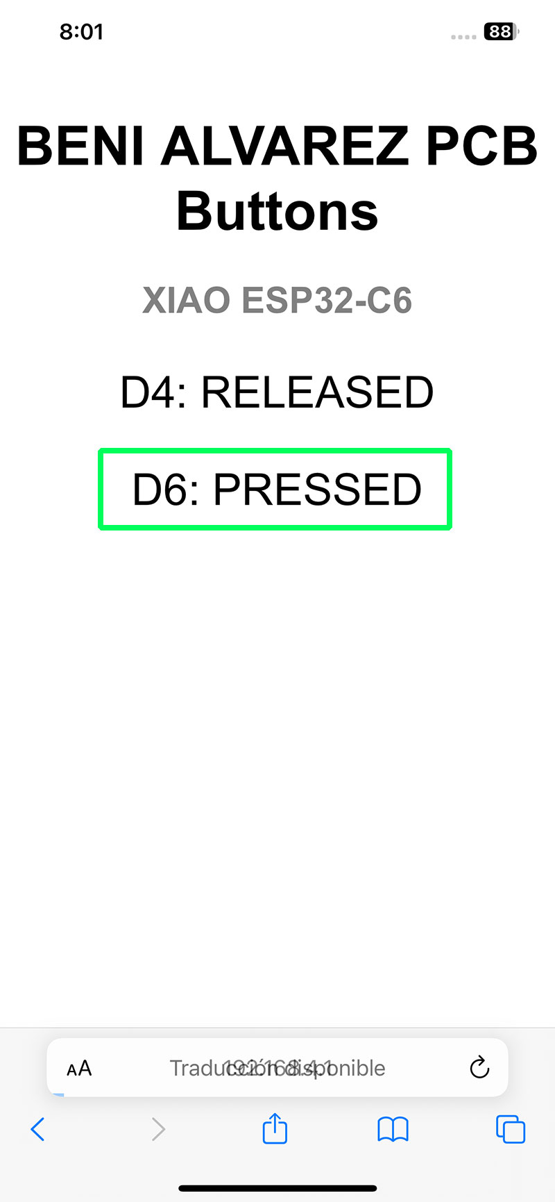
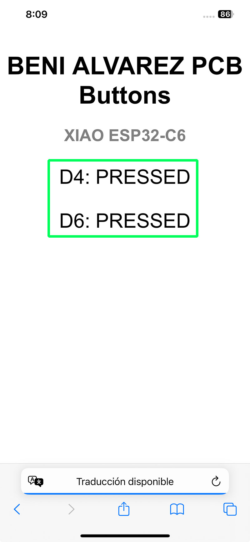
The program reads the state of the two buttons connected to pins D4 and D6 on my PCB. Whenever a button is pressed or released, its state is updated both on a web page and in the serial monitor, giving me two different ways to verify that communication is working correctly.
To make the system cleaner and more efficient, the code does not continuously send data. Instead, it detects state changes and only sends information when an actual event occurs. This avoids unnecessary repeated messages and makes the communication much clearer.
Arduino code · 01esp32_WifiButtons.ino Show code
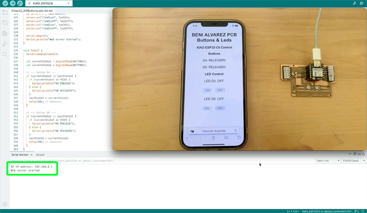
Once the program is uploaded, the serial monitor displays the IP address assigned to the XIAO within its own network. In my case, this address is 192.168.4.1. By connecting to the Wi-Fi network created by the board and entering this IP in a browser, I can access a simple web page that shows the button states in real time.
High quality video available on my YouTube channel ↗️.
Wi-Fi LED control
Taking advantage of the fact that my PCB also includes two LEDs, I expanded the previous Wi-Fi example to add control over them directly from the web interface.
In this case, besides visualizing the state of the buttons, I added options on the page to turn the LEDs on and off remotely. This means the communication is no longer only about reading data (input), but also about sending commands (output), making the system more complete and interactive.
At the same time, I kept the previous behavior, so the system still reports when the buttons are pressed or released, both on the web page and in the serial monitor. This creates a bidirectional interaction: on one side I receive information from the board, and on the other, I can send actions back to it.
With this small improvement, the project starts to feel closer to a real communication system, where devices are not only monitored but also controlled remotely through the network.
Arduino code · 01esp32_WifiButtonsLeds.ino Show code
High quality video available on my YouTube channel ↗️.
However, the way the system is used does evolve. While the communication was previously focused on reading data (button states), it now also includes control actions, allowing the client to send commands to the server to turn the LEDs on or off.
This means that, even though the network model remains the same, the system becomes bidirectional, combining monitoring and control within the same HTTP-based communication structure.
Document your work on the group work page and reflect on your individual page what you learned.
In this initial phase of the assignment, I started working with two different communication methods: BLE and Wi-Fi. This has helped me begin to understand, in a more practical way, how different devices can interact within a system.
On one hand, with BLE I explored a lighter and more structured approach, based on services and characteristics identified by UUIDs. It was interesting to see how addressing does not follow a traditional model, but instead is organized in a more abstract way, defining “where” and “how” data is exchanged inside the device.
On the other hand, with Wi-Fi I worked with a model much closer to what we use in everyday life, based on IP addressing and HTTP communication. Being able to access a web page hosted by the microcontroller itself makes everything more visual and intuitive, and helps to better understand how communication works within a local network.
During this process, I also realized how hardware limitations directly influence design decisions. In my case, the PCB design and the use of certain pins prevented me from easily using wired protocols such as I2C or UART, which significantly reduced my options and pushed me to prioritize wireless solutions.
Overall, this work is helping me build a clearer understanding of how communication systems operate and, more importantly, how to choose the most appropriate solution depending on the context, the available resources, and what I will need to implement later in my project.
Individual assignment
Design, build and connect wired or wireless node(s) with network or bus addresses and a local input and/or output device(s).
CONNECTIONS BETWEEN 2 ESP32C6 – Temperature and humidity sensor
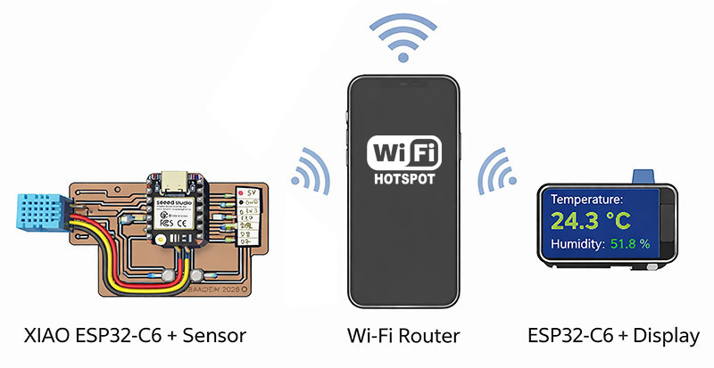
In this case, I wanted to go one step further in device communication by connecting two ESP32-C6 boards within the same network.
The idea was to reuse the previous work from week 9, where I had already worked with a DHT11 temperature and humidity sensor on my PCB using the XIAO RP2040. For this exercise, I replaced the microcontroller with a XIAO ESP32-C6, which is responsible for reading the sensor data and sending it over Wi-Fi.
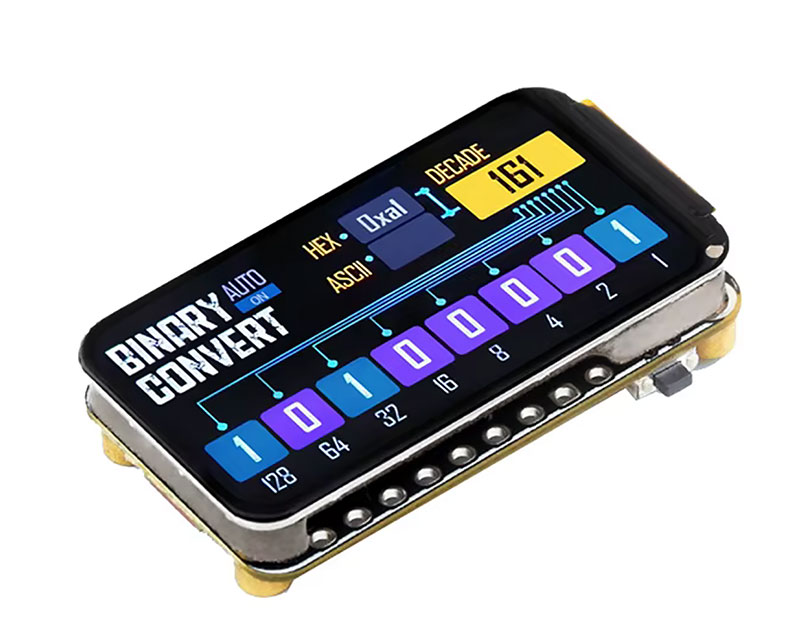
As the receiving device, I used another board, a Waveshare ESP32-C6 with a 1.47-inch display, where the temperature and humidity values are shown. In this way, I moved from an isolated system to a distributed one with two nodes communicating with each other.
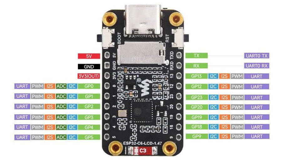
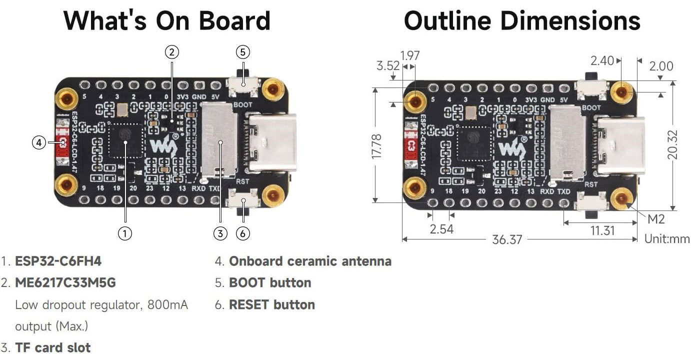
Waveshare ESP32-C6-LCD-1.47 documentation: Waveshare ESP32-C6-LCD-1.47
Main features of the Waveshare ESP32-C6-LCD-1.47
| Feature | Waveshare ESP32-C6-LCD-1.47 |
|---|---|
| Microcontroller | ESP32-C6 |
| Processor | 32-bit RISC-V single-core, up to 160 MHz |
| Low-power core | 32-bit RISC-V low-power core, up to 20 MHz |
| Wireless connectivity | 2.4 GHz Wi-Fi 6 and Bluetooth LE 5 |
| Flash memory | 4 MB |
| ROM | 320 KB |
| SRAM | 512 KB HP SRAM + 16 KB LP SRAM |
| Display | 1.47-inch LCD |
| Screen resolution | 172 × 320 pixels |
| Display color | 262K colors |
| USB connector | USB Type-C |
| Storage expansion | TF card slot |
| Antenna | Onboard ceramic antenna |
| User buttons | BOOT button and RESET button |
| GPIO expansion | Multiple GPIO pins for UART, I2C, I2S, PWM and ADC |
Wi-Fi communication using a mobile hotspot (HTTP data exchange)
Both devices connect to the same Wi-Fi network, in this case using a mobile phone as a hotspot, which makes it possible to establish communication based on IP addressing. This introduces, in a very practical way, key networking concepts such as the client-server model and data transmission over a network.
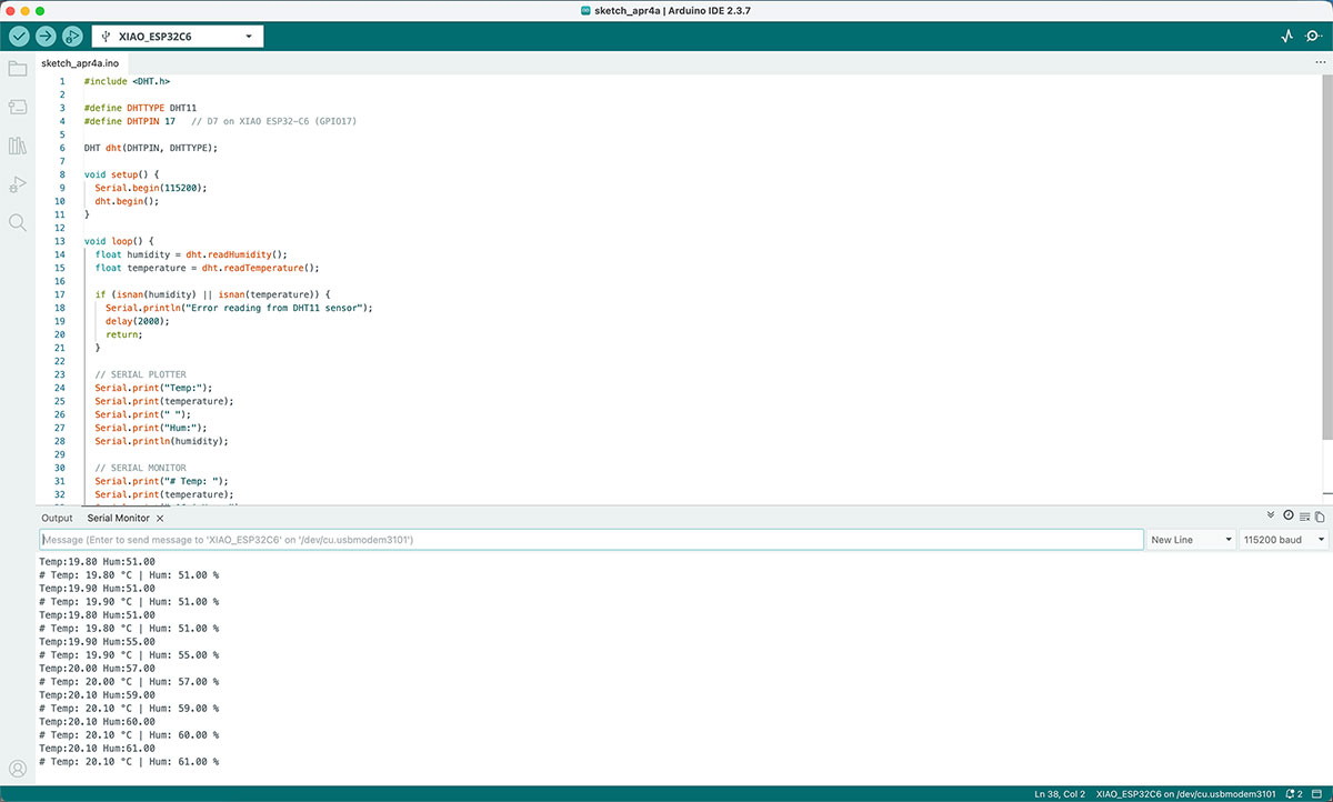
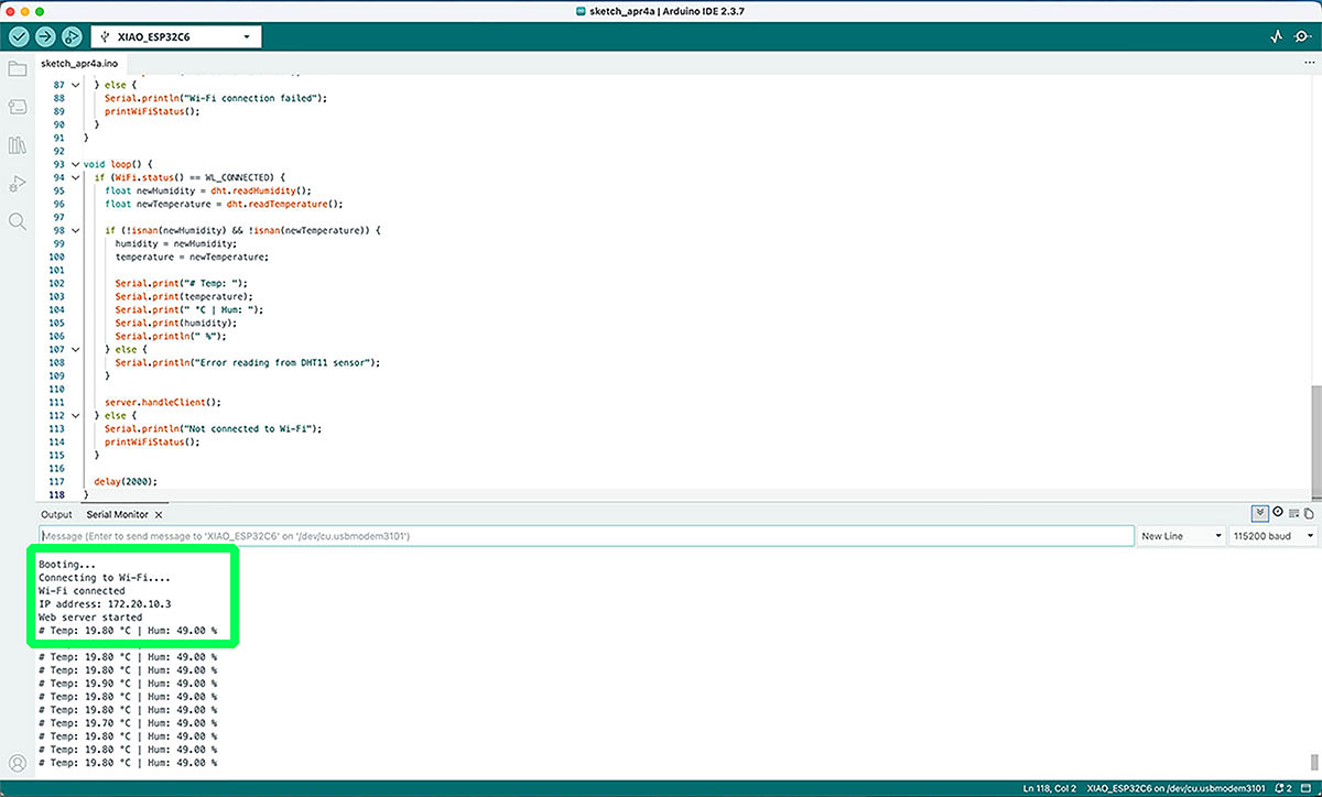
As a starting point, I reused the DHT11 code developed earlier and checked that the XIAO ESP32-C6 was correctly reading the data in the serial monitor. Once this was validated, the next step was to connect the device to the Wi-Fi network and make it publish the sensor values.
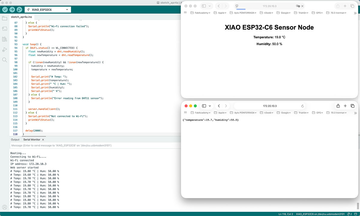
To do this, I configured the XIAO as a small web server, capable of providing the data in two formats:
- a simple web page accessible from the IP assigned by the router
- a specific endpoint with the data in JSON format
Once connected to the network, the device receives an IP address (in my case, 172.20.10.3), which I can type into a browser to view the published data:
- At
http://172.20.10.3/, the values are displayed in a simple web page - At
http://172.20.10.3/data, the data is available in JSON format
Arduino code · HRTemp_ESP32_1XIAO.ino Show code
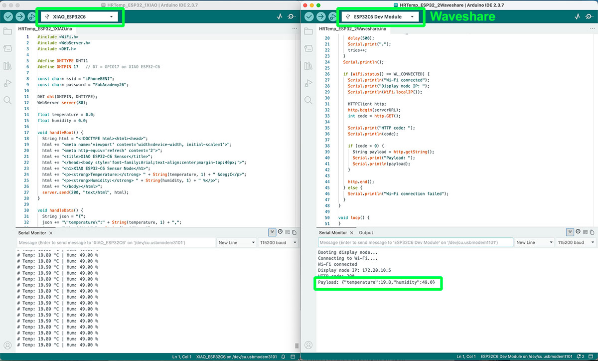
Next, I moved on to the Waveshare ESP32-C6, configuring it as a client on the same network. As a first step, I developed a sketch that connects to Wi-Fi and periodically requests the sensor data from the XIAO endpoint.
At the beginning, this data was displayed in the serial monitor, which allowed me to confirm that communication between both devices was working correctly.
Once the reception was validated, I used the ArduinoJson library to parse the received data, separating the temperature and humidity values in a structured way.
Arduino code · HRTemp_ESP32_2Waveshare_LCD.ino Show code

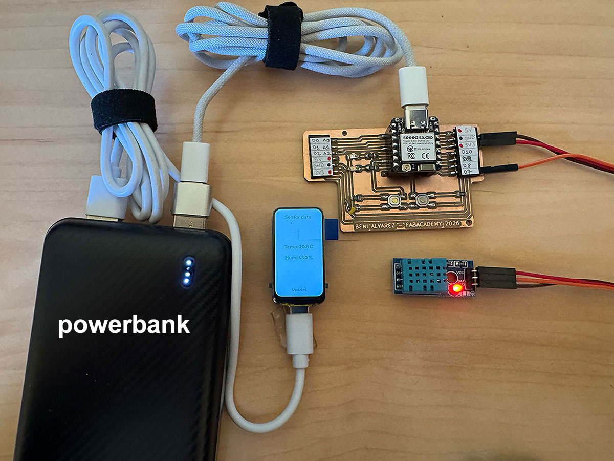
Finally, I completed the system by displaying the values directly on the Waveshare screen. At that point, the setup was complete: one device measures and publishes the data, while the other receives, processes, and displays it.
High quality video available on my YouTube channel ↗️.
High quality video available on my YouTube channel ↗️.
http://172.20.10.3/data, while the Waveshare board acted as the client, sending HTTP requests to that IP address in order to retrieve the information. In this way, the addressing was based on the use of IP addresses inside the same local network, following a classic client-server model in which one node provides data and the other requests it periodically.
Problems and solutions
During the development of the communication system between both ESP32 boards and the data visualization on the Waveshare display, I started from an official example code provided in the Waveshare documentation. This example was very helpful to correctly initialize the screen and work with the LVGL graphical environment. From there, I progressively adapted the code to integrate Wi-Fi connectivity, data reception, and on-screen visualization.
One of the first issues I encountered was the Wi-Fi connection, as the ESP32 was not able to connect to the iPhone hotspot. After several attempts, the solution was to enable the “Maximize Compatibility” option on the phone, which allowed the connection to be established successfully.
I also faced problems with the serial monitor on the Waveshare board, which initially showed no output at all. This was solved by enabling the “USB CDC On Boot” option, allowing proper use of the serial interface for debugging.
During compilation, a critical error appeared related to the LVGL library, caused by the absence of the lv_conf.h file. The solution was to generate this file from the lv_conf_template.h, place it in the correct directory, and configure it properly.
Later on, additional errors appeared due to LVGL version incompatibilities. The Waveshare example code is designed to work with LVGL 8, while I was initially using a newer version of the library. This was solved by using the LVGL version included in the Waveshare example, ensuring full compatibility.
Finally, there were some minor issues related to missing font resources, which were resolved by using default compatible fonts without modifying the internal library configuration.
Overall, most of the challenges were related to environment setup and library compatibility, rather than the project logic itself. Once these issues were resolved, the system worked as expected, allowing sensor data to be read, sent over Wi-Fi in JSON format, and displayed in real time on the screen.
Bluetooth Low Energy (BLE) communication between ESP32 devices
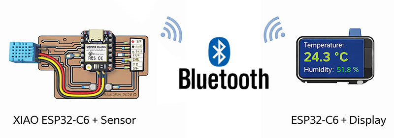
After implementing communication using Wi-Fi through a mobile hotspot, I decided to explore a second wireless communication approach between both boards: Bluetooth Low Energy (BLE).
The main goal in this case was to remove the dependency on an external Wi-Fi network and establish a direct communication between devices, using a typical BLE architecture based on a server–client model.
To achieve this, the XIAO ESP32-C6 was configured as a BLE server, responsible for reading the temperature and humidity data from the DHT11 sensor and sending it through a BLE characteristic. On the other side, the Waveshare ESP32-C6 with display was configured as a BLE client, scanning nearby devices, connecting to the server, and periodically reading the transmitted values.
After several iterations and adjustments, a stable connection between both boards was successfully established. The Waveshare device was able to connect to the XIAO and receive real-time sensor data, displaying temperature and humidity values through the serial monitor. In this case, the data was not implemented on the Waveshare screen, as verifying the correct reception through the serial monitor was sufficient to confirm that the communication between both devices was working properly.
This demonstrates that it is possible to achieve a fully functional communication between two ESP32-C6 boards using BLE, without relying on any Wi-Fi infrastructure, making it a very interesting alternative for embedded systems.
Arduino code XIAO · HRTemp_BT_1XIAO.ino Show code
Arduino code WAVESHARE · HRTemp_BT_2Wave.ino Show code

Problems and solutions
During the development of the BLE communication, several issues appeared, mainly related to the device discovery and connection process.
One of the first problems was related to missing BLE libraries in the Arduino environment. This was solved by properly installing the NimBLE-Arduino library
Later, although the XIAO worked correctly as a BLE server and could be detected using external apps like nRF Connect, the Waveshare device struggled to clearly identify it during scanning. Many detected devices did not show a name, making it difficult to determine which one corresponded to the XIAO.
To solve this, a comparison was made between scan results with the XIAO turned on and off, which allowed identifying the correct BLE address. Once identified, the client was configured to connect directly to that address, successfully establishing communication.
Another issue observed was that the BLE address could change between executions, causing inconsistent behavior. However, after restarting the XIAO, the communication became stable and the connection was maintained, allowing continuous data reading.
In conclusion, BLE enables a direct and efficient communication between devices without requiring a network, but the setup and connection process can be more complex and less robust than Wi-Fi, especially in environments with multiple nearby devices.
ESP-NOW protocol for direct ESP32-to-ESP32 communication
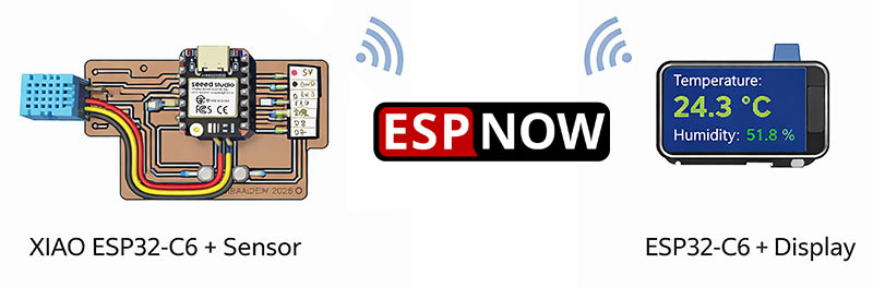
After testing different wireless communication options such as Wi-Fi and Bluetooth Low Energy, I decided to explore a third alternative: ESP-NOW, a protocol developed by Espressif for direct communication between ESP32 devices without requiring a conventional Wi-Fi network.
In this case, I configured a simple architecture with two nodes. On one side, the XIAO ESP32-C6 was responsible for reading the temperature and humidity values from the DHT11 sensor. On the other side, the Waveshare ESP32-C6 with display acted as the receiver and visualization device.
The first step was to obtain the MAC address of the receiver board with a simple arduino code since ESP-NOW requires explicitly defining which device the data will be sent to.
arduino · view MAC address Show code
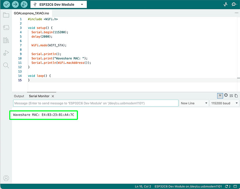
Once that address was known, the XIAO board was configured as the sender, periodically transmitting the sensor readings using a custom data structure.
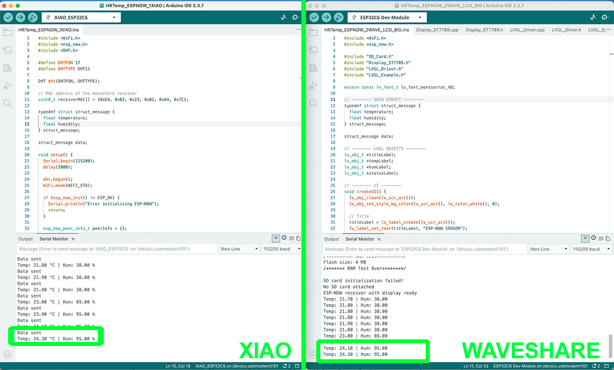
At the same time, the Waveshare board was configured as the receiver, registering a callback function that was executed every time new data arrived. At first, in order to validate the communication, the received values were displayed in the serial monitor, which made it possible to confirm quickly that the transmission was working correctly and in real time.
Once the communication was confirmed, the next step was to integrate the data into the display using LVGL, reusing part of the code previously developed during the Wi-Fi stage. In this way, the received values were dynamically updated on the graphical interface, showing the temperature as the main value and the humidity as secondary information.
Simple physical tests were also carried out, such as breathing on the sensor, which made it possible to observe immediate changes in the values on both the sender and the receiver. This confirmed that the system was responding correctly in real time.
As a final improvement, I worked on the visual design of the interface, increasing the font size for the temperature and reorganizing the layout to make the display cleaner, clearer, and easier to read, closer to the appearance of a real product.
Arduino code XIAO · HRTemp_ESPNOW_1XIAO.ino Show code
Arduino code WAVESHARE · HRTemp_ESPNOW_2WAVE_LCD_BIG.ino Show code
High quality video available on my YouTube channel ↗️.
To achieve this, the MAC address of the receiver board (Waveshare) was obtained and configured in the code of the sender board (XIAO). This establishes a point-to-point communication, where each data packet is sent directly to a known destination.
This approach enables a fast, lightweight, and infrastructure-free communication, since it does not require routers, access points, or any intermediate network elements. As a result, ESP-NOW becomes a very efficient solution for direct device-to-device communication.
Problems and solutions
During the development of the ESP-NOW communication, several problems appeared, mainly related to the integration of the display and the customization of the graphical interface.
One of the first issues was that, although the data was being received correctly and could be verified in the serial monitor, the screen remained black. This was caused by an incomplete display initialization, so it was necessary to make sure that the display and LVGL initialization functions were executed in the correct order.
Another challenge was related to the screen orientation. When I tried to show the information in horizontal mode, some elements appeared rotated, misplaced, or visually corrupted. This required modifying the low-level configuration of the ST7789 driver, adjusting the orientation register until a valid result was found. Even so, achieving a fully clean horizontal layout was more complex than expected, so I kept working with the stable vertical version.
Another issue appeared when trying to improve the visual design by using larger fonts in LVGL. At first, I enabled them in the lv_conf.h file, but nothing changed because I was editing the wrong configuration file. After some debugging, I found that the correct file was located inside the library path /libraries/lvgl/src/. Once this was corrected, it became possible to enable larger fonts such as Montserrat 28 and Montserrat 48.
Finally, I also confirmed that designing interfaces with LVGL requires a certain amount of fine adjustment, especially regarding alignment, font size, spacing, and visual hierarchy. Even so, once the basic logic was understood, it became possible to build an interface that was not only functional, but also much more visually polished.
Wireless communication comparison: Wi-Fi vs. BLE vs. ESP-NOW
| Feature | Wi-Fi (HTTP) | Bluetooth Low Energy (BLE) | ESP-NOW |
|---|---|---|---|
| Network required | Yes (router or hotspot) | No | No |
| Addressing method | IP address | Device scan + services/UUID | MAC address (direct) |
| Communication type | Client–Server | Client–Server (GATT) | Peer-to-peer |
| Ease of setup | Medium | Medium–High | Simple |
| Latency | Medium | Low | Very low |
| Range | High (depends on network) | Medium | Medium |
| Data throughput | High | Low | Medium |
| Internet access | Yes | No | No |
| Best use case | Web interfaces, APIs | Mobile interaction, sensors | Fast device-to-device communication |
Original code files for this documentation
Files for download
- BLE menssages (01esp32_BTbuttons.ino) INO · 4 Kb
- Web menssages (01esp32_WifiButtons.ino) INO · 3 Kb
- Web menssages and leds control (01esp32_WifiButtonsLeds.ino) INO · 3 Kb
- XIAO reading data from DHT11 WIFI (HRTemp_ESP32_1XIAO.ino) INO · 3 Kb
- WAVESHARE showing data WIFI. Arduino code and libraries (HRTemp_ESP32_2Waveshare_LCD.zip) ZIP · 18 Kb
- XIAO reading data from DHT11 BLE (HRTemp_BT_1XIAO.ino) INO · 2 Kb
- WAVESHARE showing data BLE (HRTemp_BT_2Wave.ino) INO · 3 Kb
- XIAO reading data from DHT11 ESPNOW (HRTemp_ESPNOW_1XIAO.ino) INO · 1 Kb
- WAVESHARE showing data ESPNOW. Arduino code and libraries (HRTemp_ESPNOW_2WAVE_LCD_BIG.zip) ZIP · 18 Kb
Networking and Communications testing for my final project
As a next step, I plan to connect my goal detection sensor with the Waveshare display, so that when a goal is detected, the score is updated in real time. This will help me move toward a wireless distributed system, which is directly aligned with the needs of my final project.
Final project development - Week11 sectionWeek questions/tasks
Final reflection
This week has been very interesting, as it allowed me to explore and compare different ways of communication between devices, both in the individual and group assignments. By implementing Wi-Fi, BLE and ESP-NOW, I gained a clearer understanding of their differences, advantages and real-world applications.
On the individual side, developing nodes with input and output and visualizing data on a display helped me understand how to design distributed systems. At the same time, the group work reinforced key concepts such as addressing and data transmission between devices.
One of the main takeaways is that there is no single ideal protocol, but rather the choice depends on the use case: Wi-Fi for connected services, BLE for interaction with mobile devices, and ESP-NOW for fast and direct communication between boards.
Finally, this week has been key for the development of my final project, confirming that wireless communication will be an essential part of the system.
Credits
I would like to thank to my wife, for her help in recording the videos.
All texts were written in Spanish and translated into English using Google Translate and ChatGPT.