Week 7: Computer-Controlled Machining
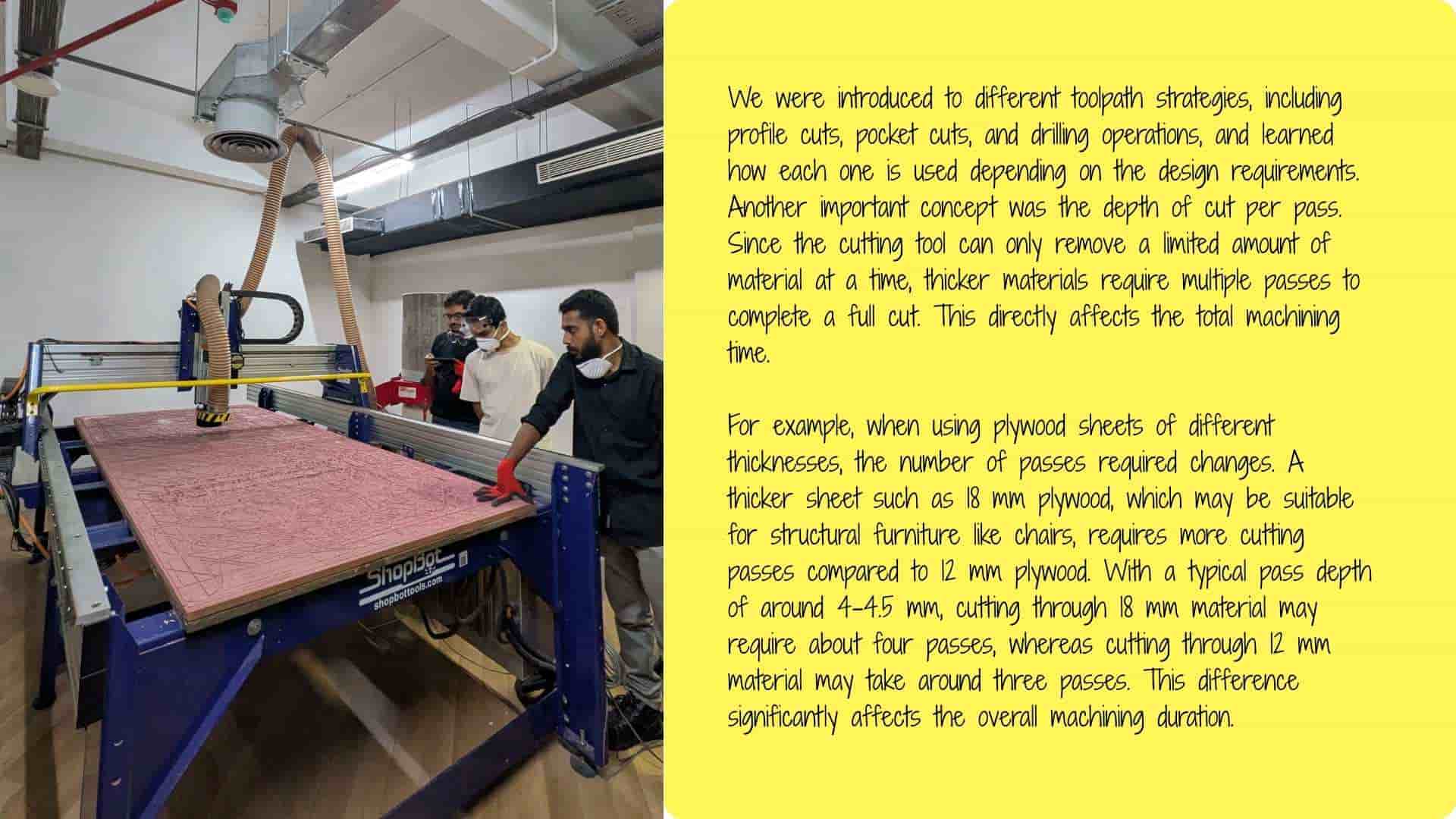
This week focuses on computer-controlled machining, where digital designs are translated into physical objects using CNC machines. The objective is to understand how large-scale components can be designed, machined, and assembled accurately using subtractive manufacturing processes.
Our Instructors for this week were Mufeed and Revisankar, along with Saheen for overall guidance
The work for this week is divided into group tasks and individual fabrication.
Hero Shot
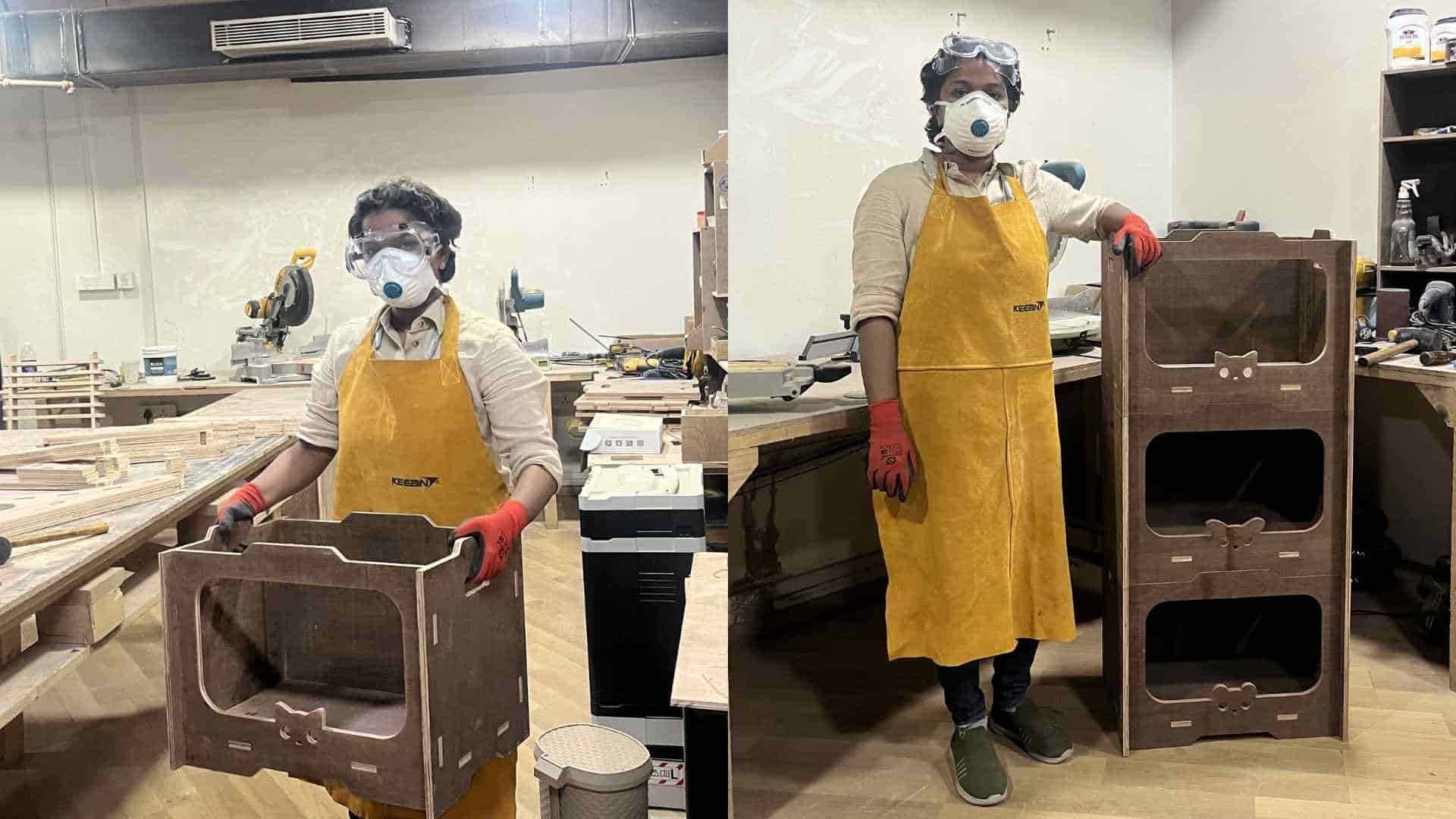
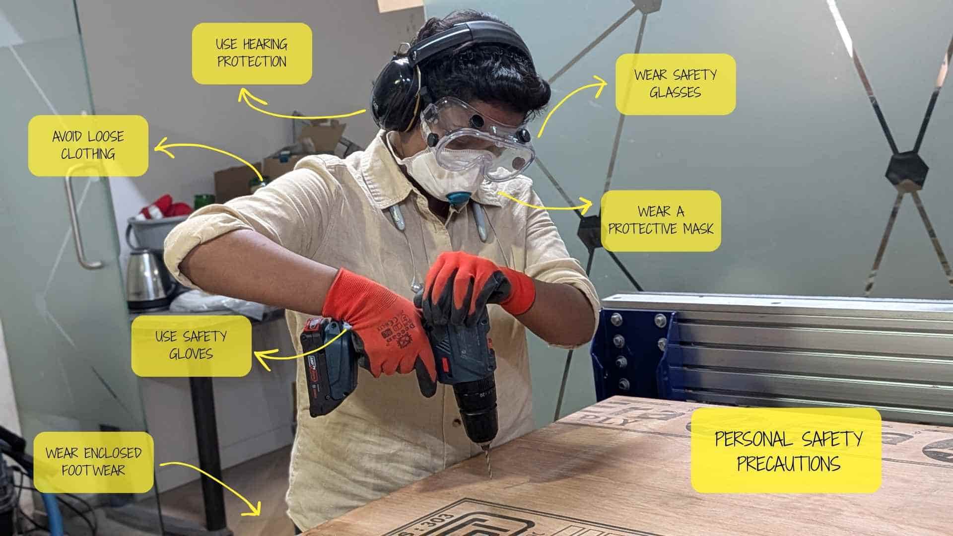
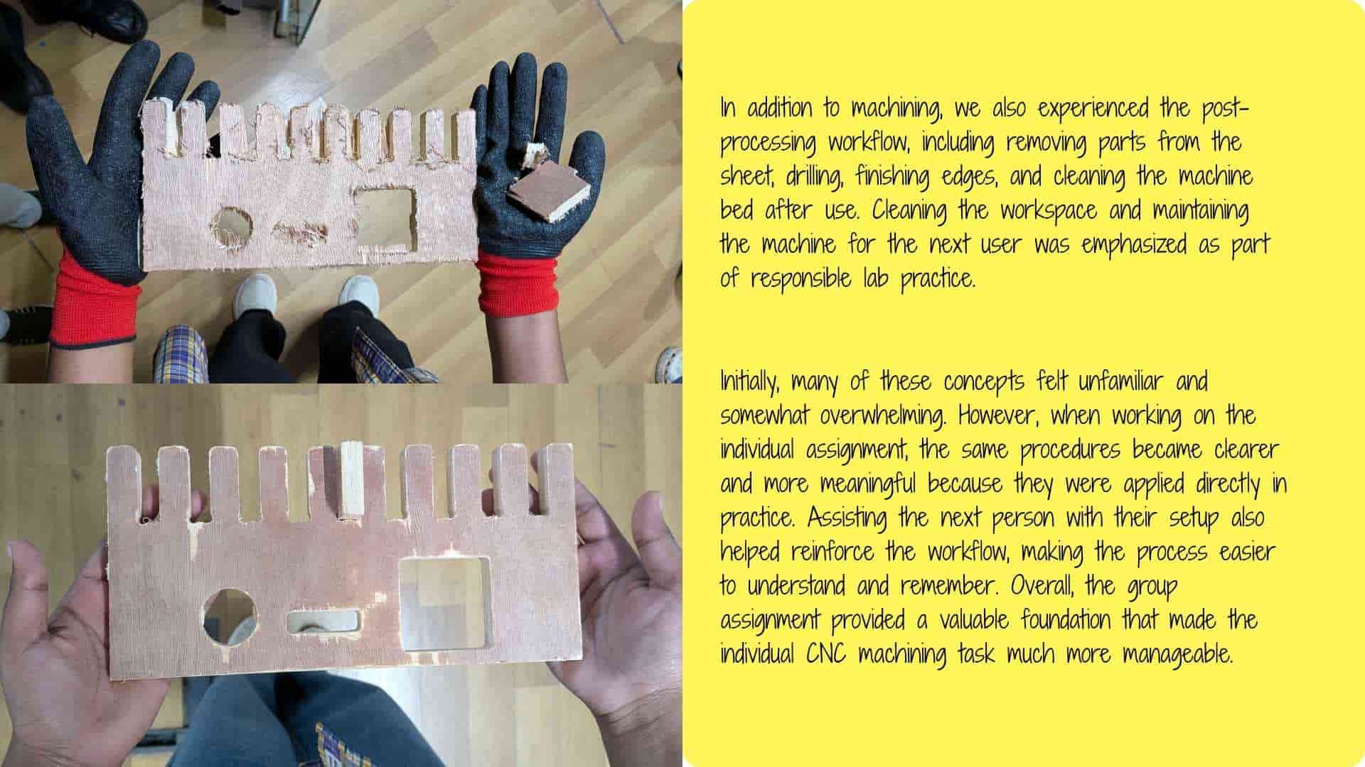
Personal Safety
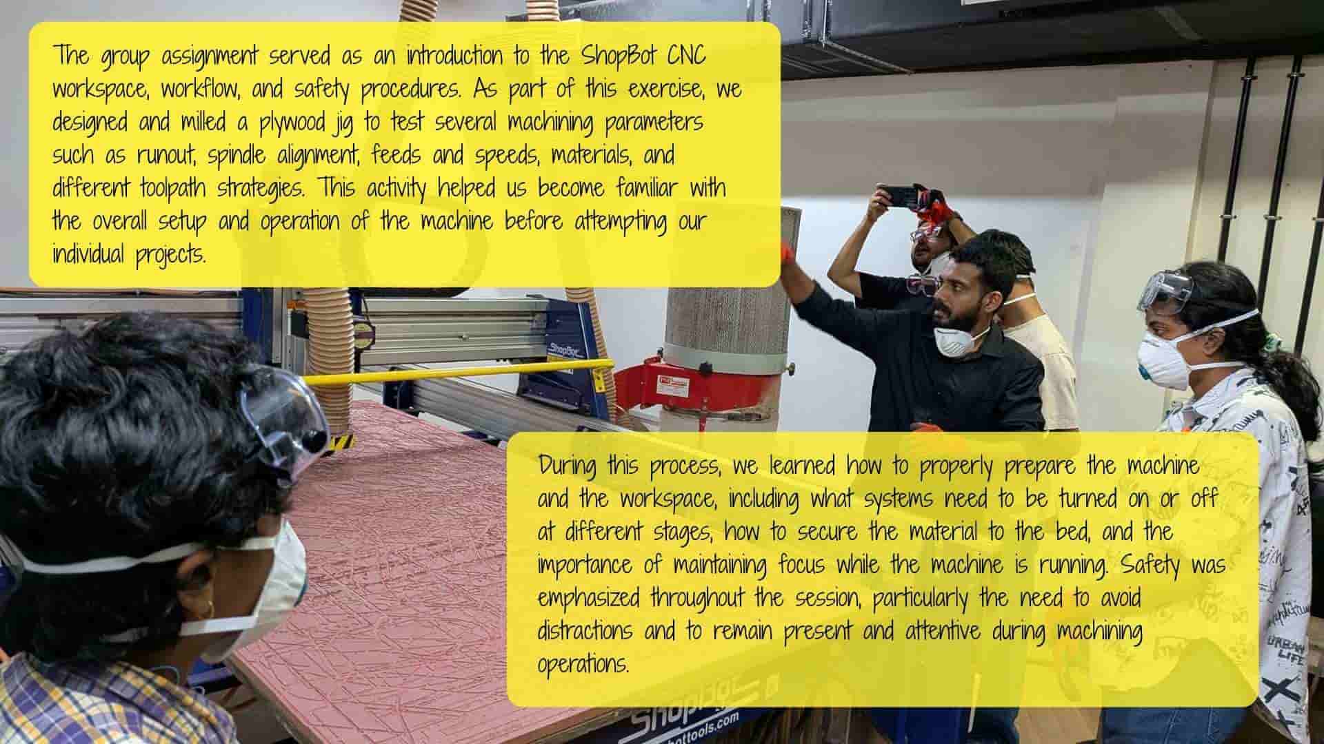
Reflection on the Group Assignment
Please follow this link to access this week's Group Assignment.
Individual Assignment
The individual assignment is to design, mill, and assemble a large object, approximately meter-scale, using the CNC machine. The goal is to explore how large components are fabricated from sheet materials and assembled into stable structures. Additional challenges are available for extra credit:
Overall, this week emphasizes the relationship between digital design, machining strategy, and physical assembly, while working at a much larger scale than previous fabrication assignments.
Designing a Modular Stackable Storage Unit in Fusion
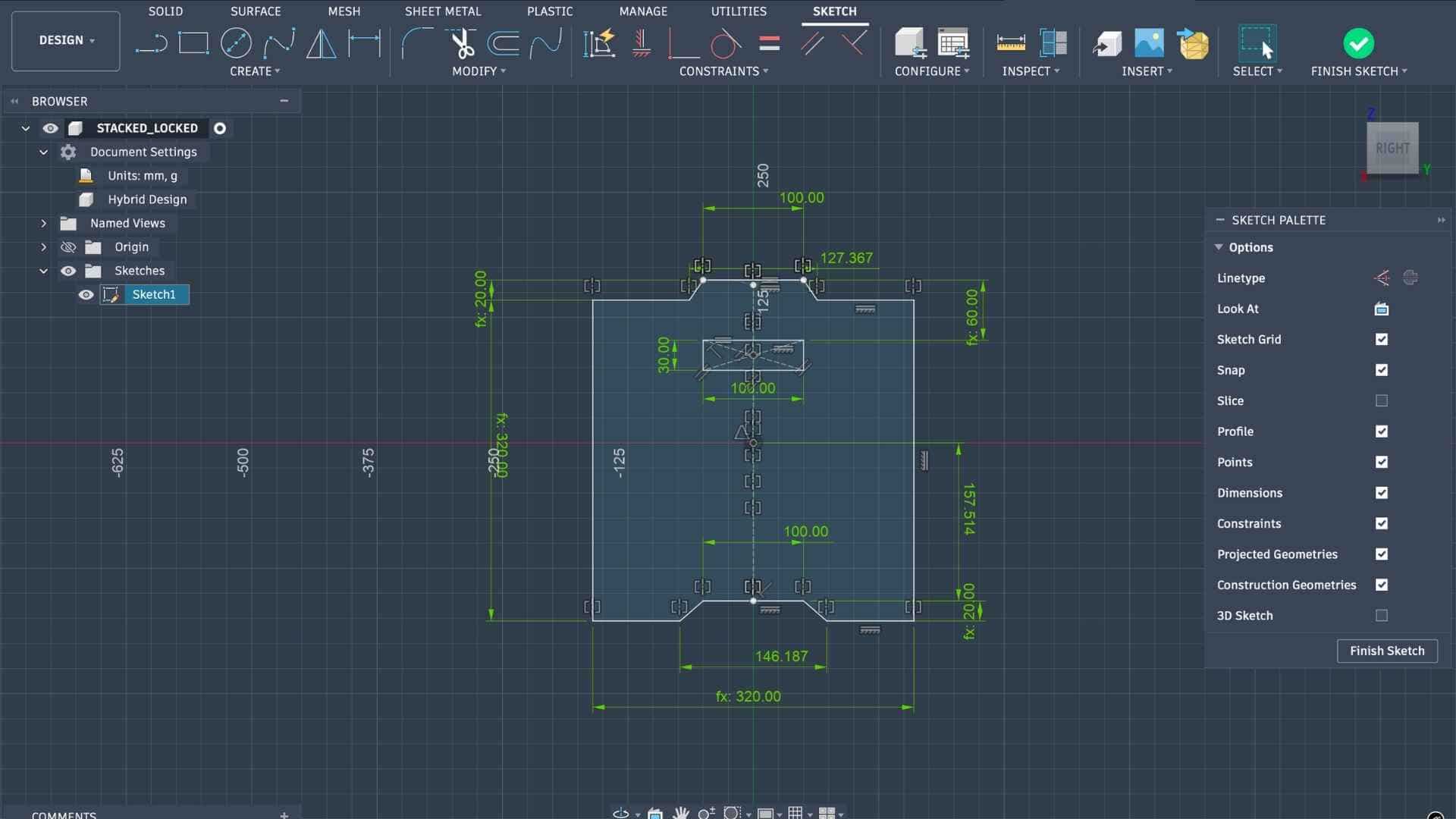
To fabricate an object using the ShopBot CNC milling machine, I decided to design a parametric modular stackable storage unit in Fusion 360. The process began with sketching the concept and identifying approximate dimensions for the storage module. After finalizing the idea, I started modeling the design in Fusion by creating the side profile sketch of the unit.
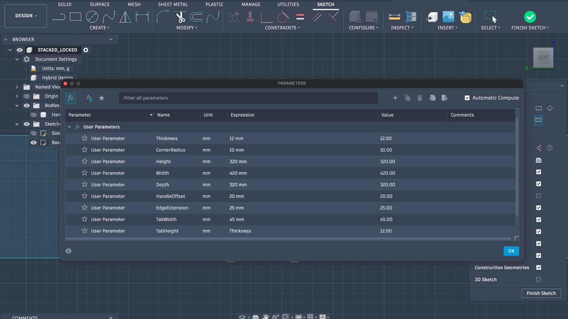
To maintain flexibility in the design, I defined parametric values using Modify → Change Parameters in Fusion. These parameters controlled key dimensions such as thickness, widths, and offsets. Using parameters ensured that any design changes could later be made easily by updating the values rather than editing multiple sketches manually.
Adding parameters
Since the storage unit is symmetrical along one axis, I modeled only half of the side profile initially and later mirrored it to generate the full geometry. After completing the side profile, I created another sketch on the corresponding plane and used Project to reference existing geometry. From this, I developed the front panel profile, again starting with half of the geometry.
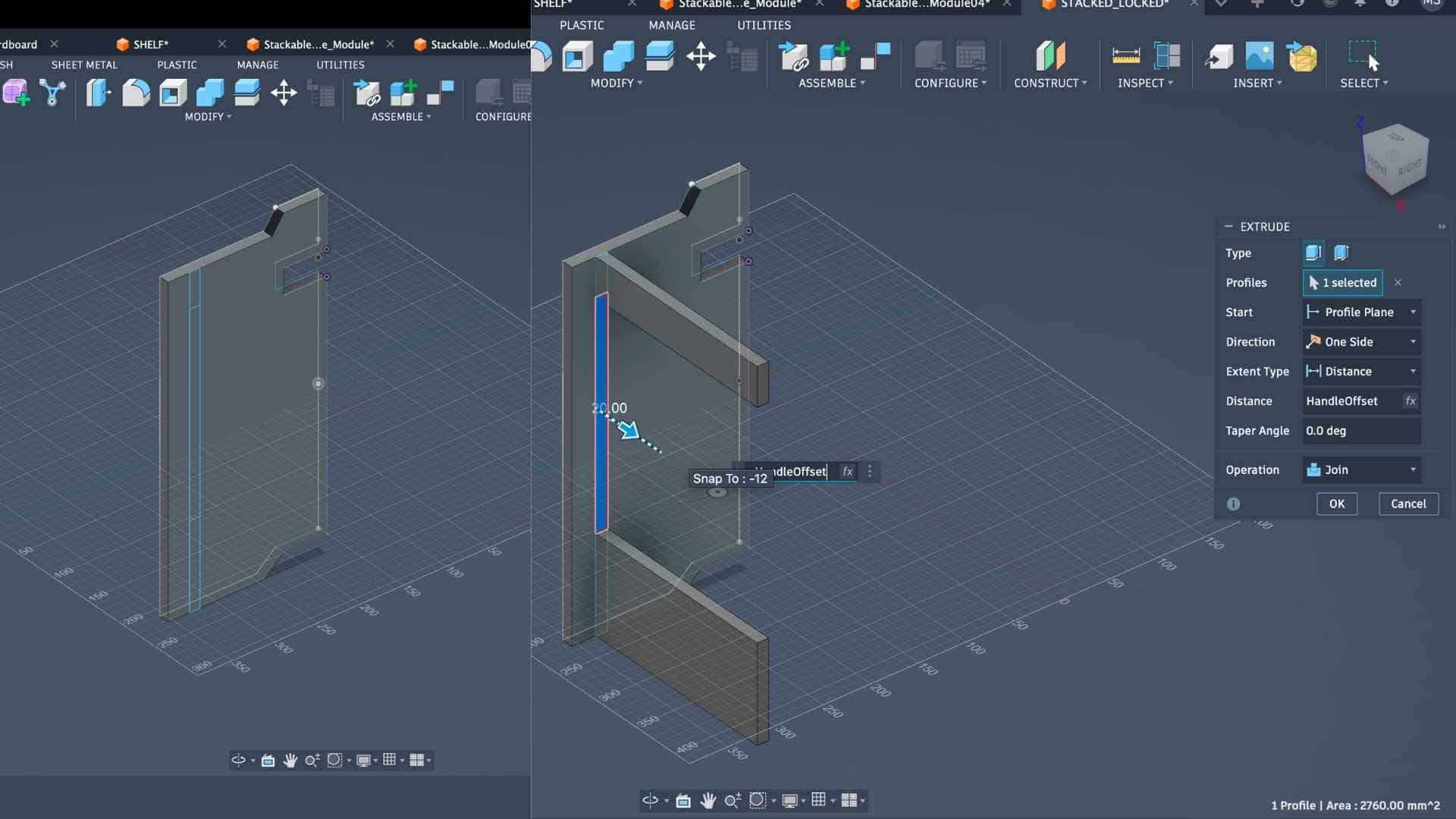
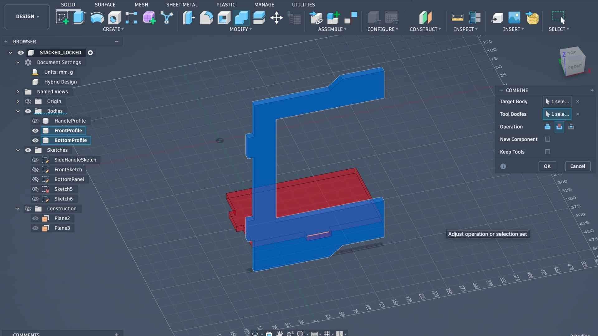
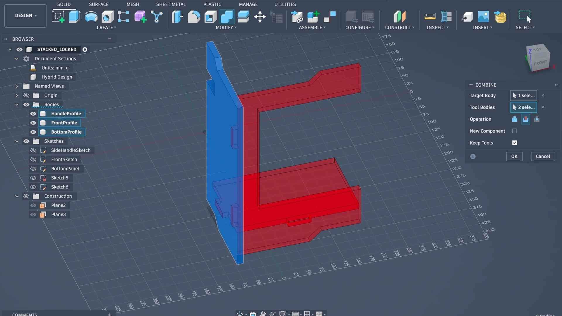
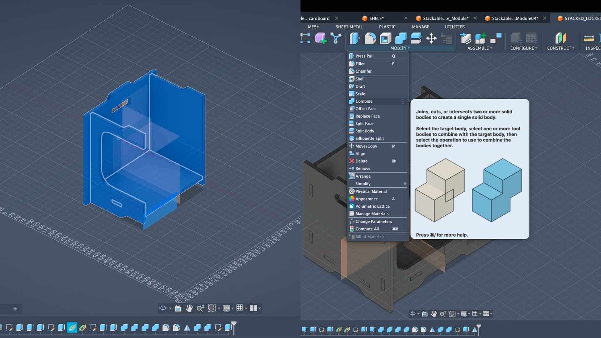
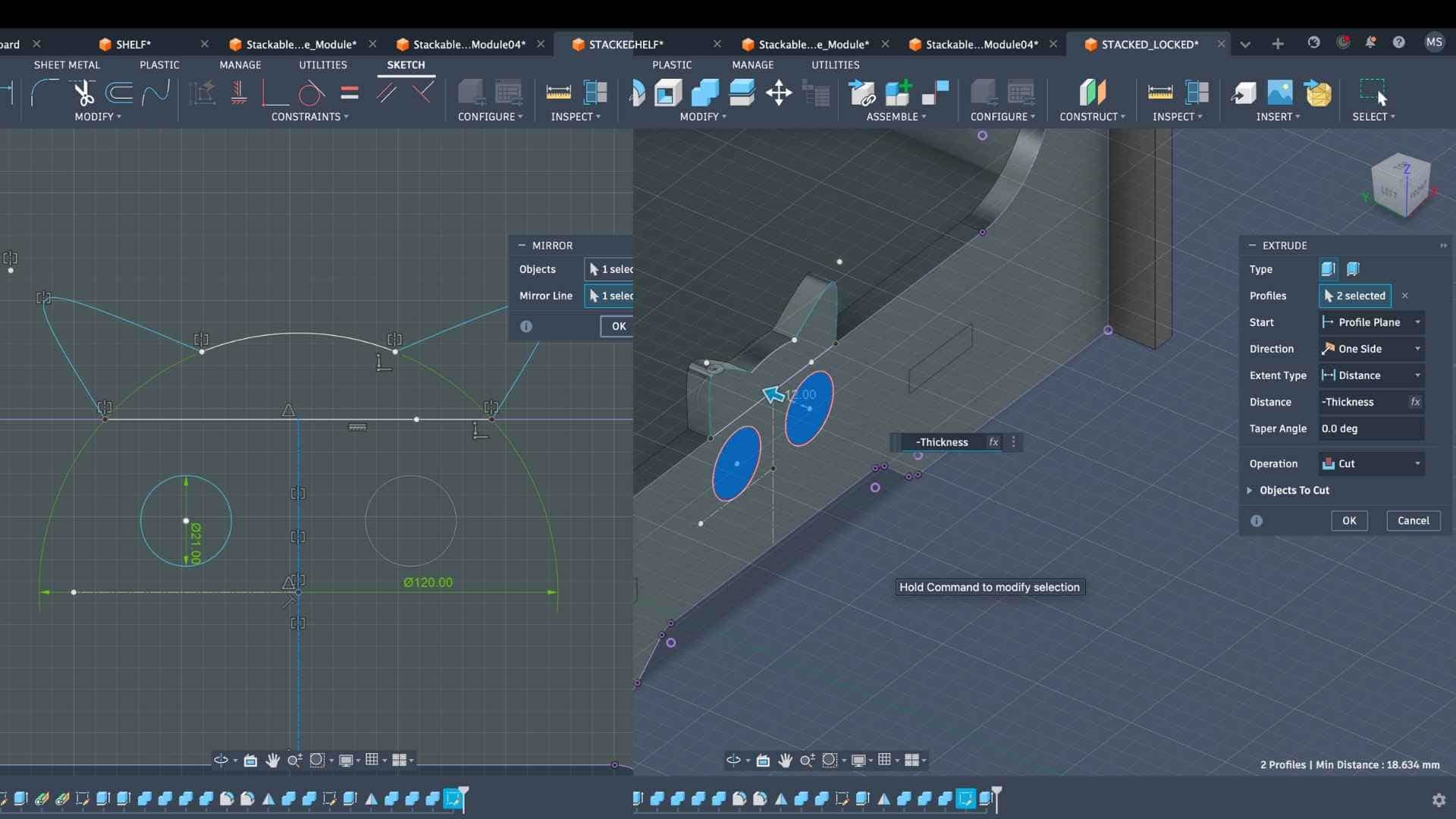
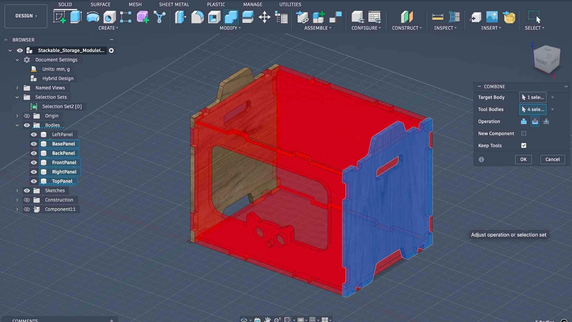
Next, I added the tabs and slots required for press-fit assembly so that the tabs of one panel would fit into the slots of the corresponding panel. Once these features were created, I used operations such as Combine, Join, and Cut to generate separate bodies and refine the joinery. The Mirror tool was then used to replicate the half geometry and complete the panels.
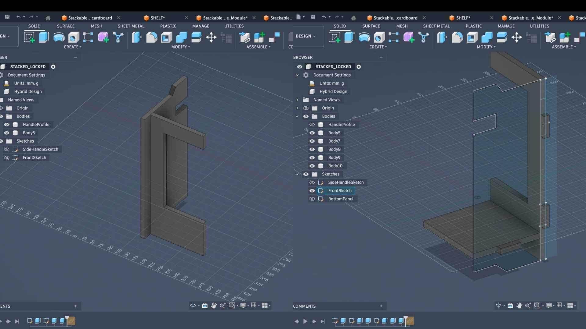
Combine and Cut Operations
Throughout the modeling process, I repeatedly used tools such as Sketch, Project, Mirror, Combine, Join, and Cut while referencing the previously defined parameters (for example, adding or subtracting the material thickness). This approach ensured that the design remained adaptable and easy to modify.
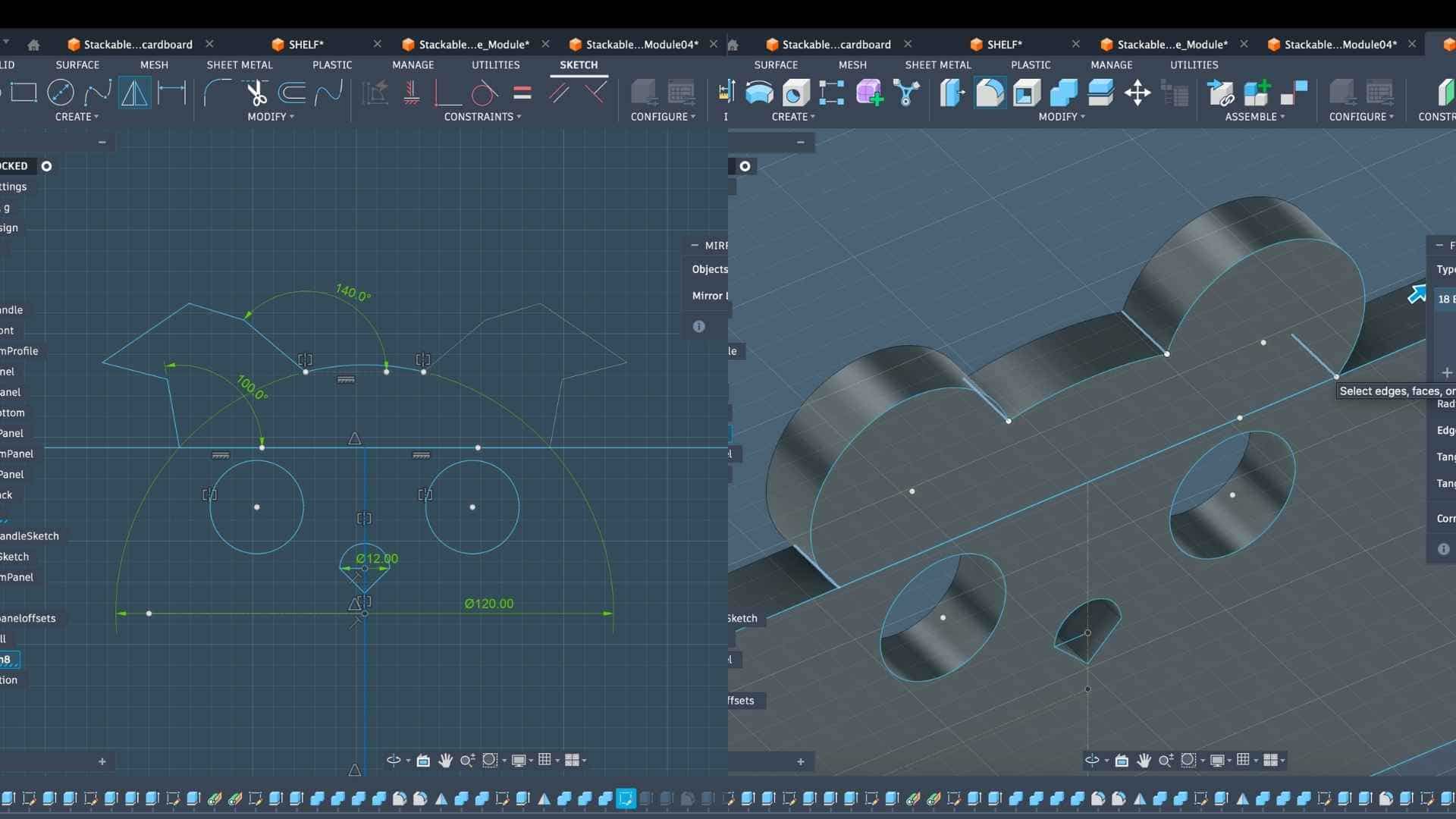
Mirroring Using Tangent Planes

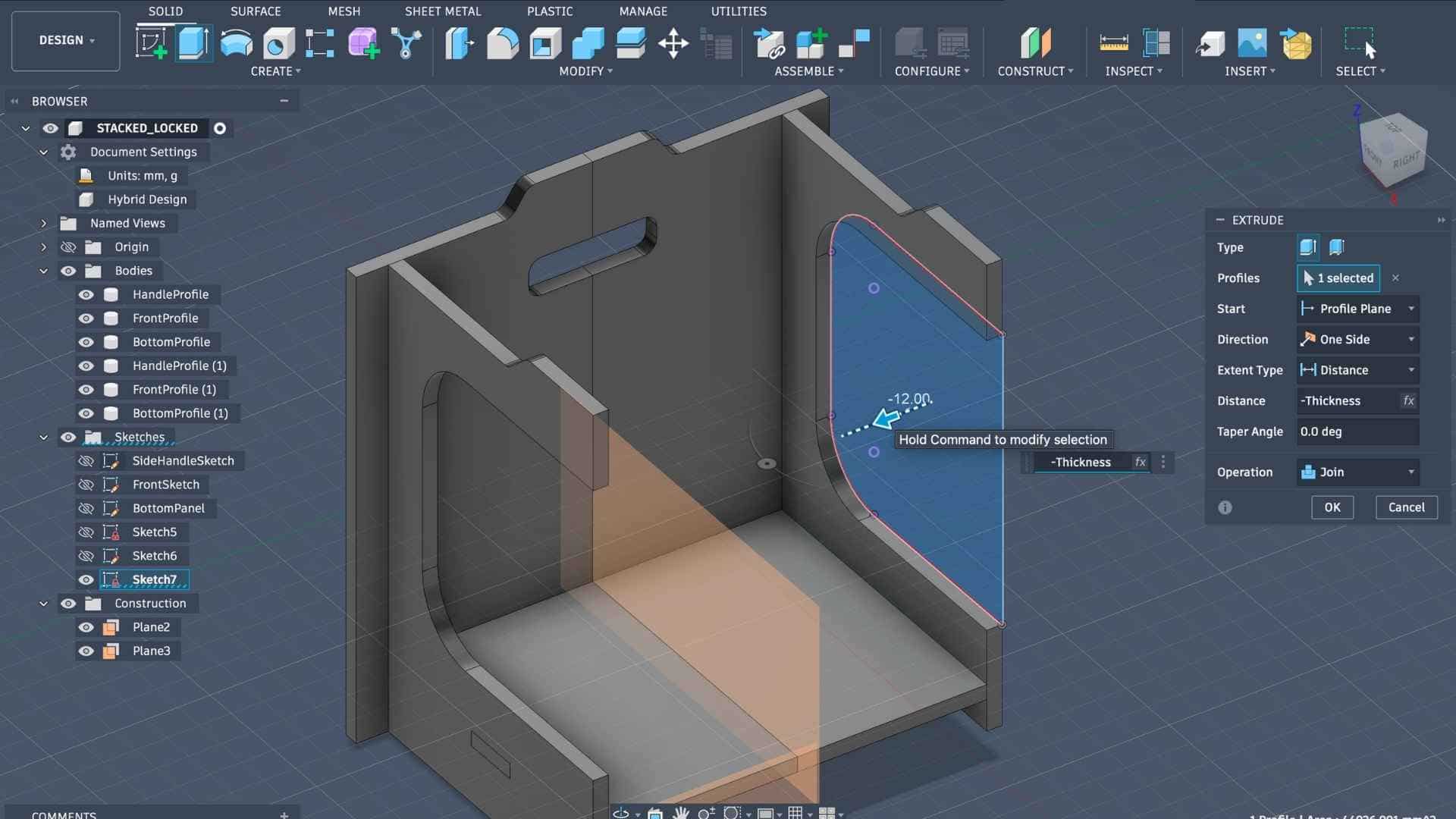
The front panel was designed as a frame with an open central area to allow access to the stored items, while the back panel needed to remain closed. To achieve this, I created an additional sketch on the back panel plane and extruded it to fill the hollow portion, creating a solid back panel.
Inspiration for the Front Panel
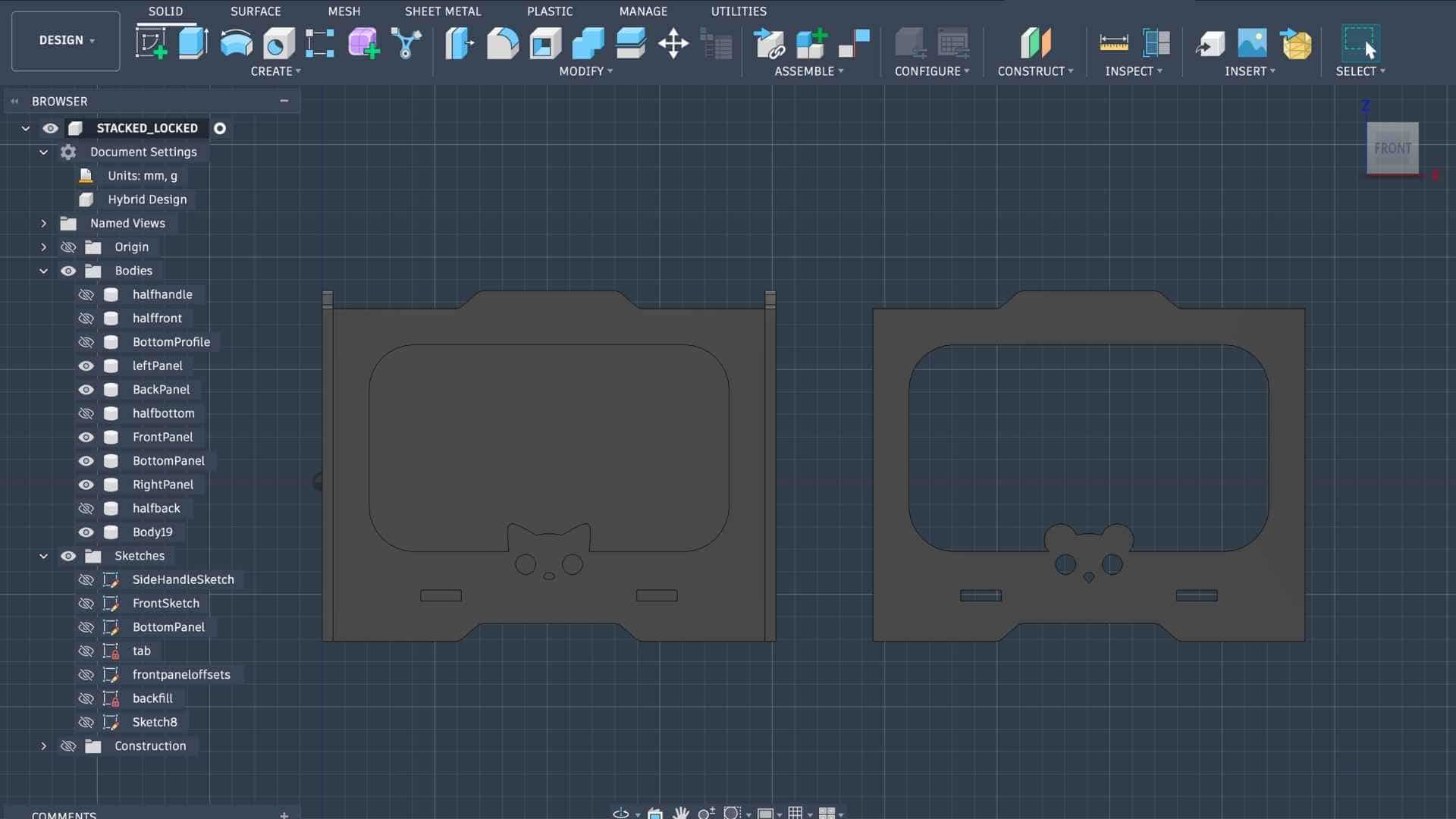
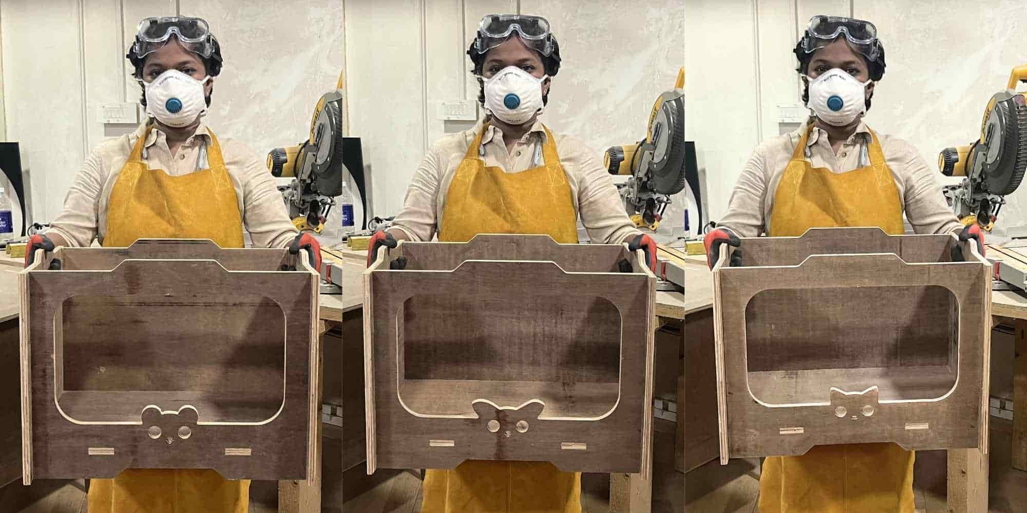
After completing one full storage unit, I added a small decorative element on the front panel. Inspired by a pattern on my socks, I designed a simple animal face motif. Since the storage units were intended to be stackable and modular, I decided to create three variations of the design so that each unit could be visually distinguished.
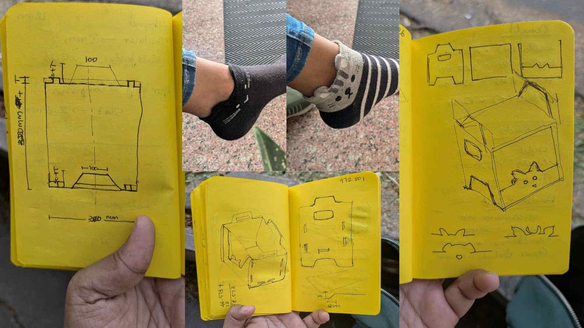
The main difference between the units was the shape of the ears, while the rest of the face remained similar. For example, one resembles a cat, while the others can be interpreted as different animals depending on the ear shape.
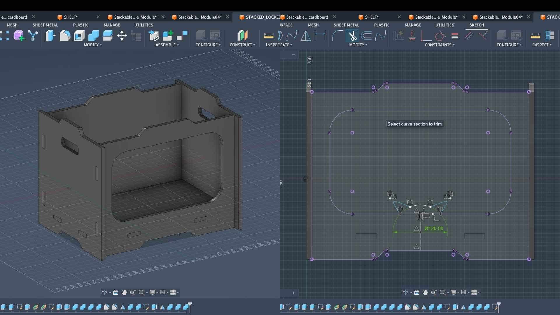
To create these variations, I sketched half of the face profile (eyes and ears) and mirrored it to complete the design. The sketch was then copied and modified to produce alternative ear shapes, resulting in three slightly different front panels.
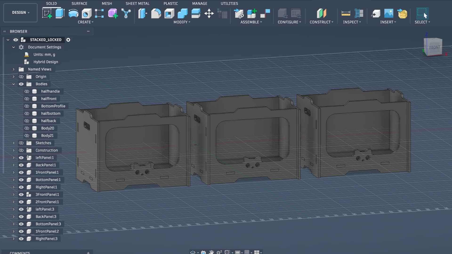
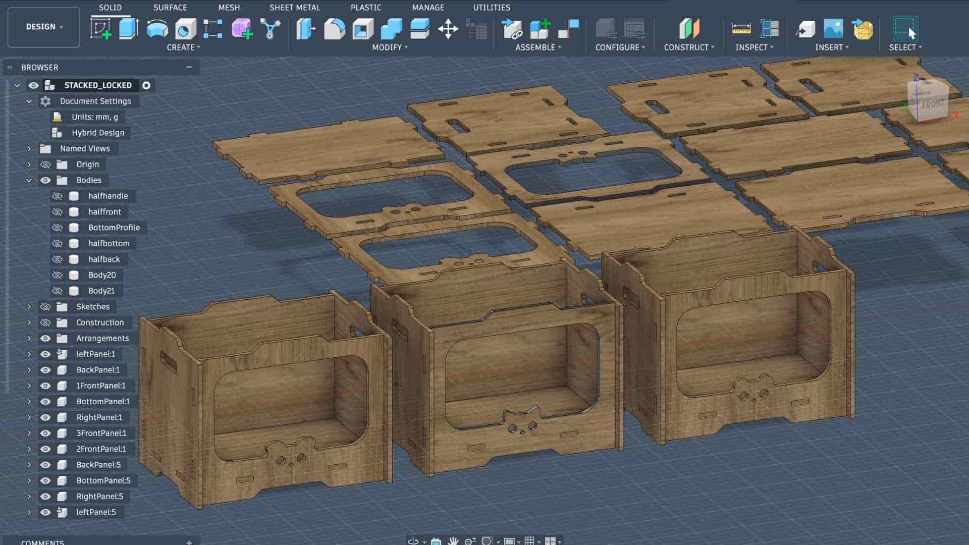
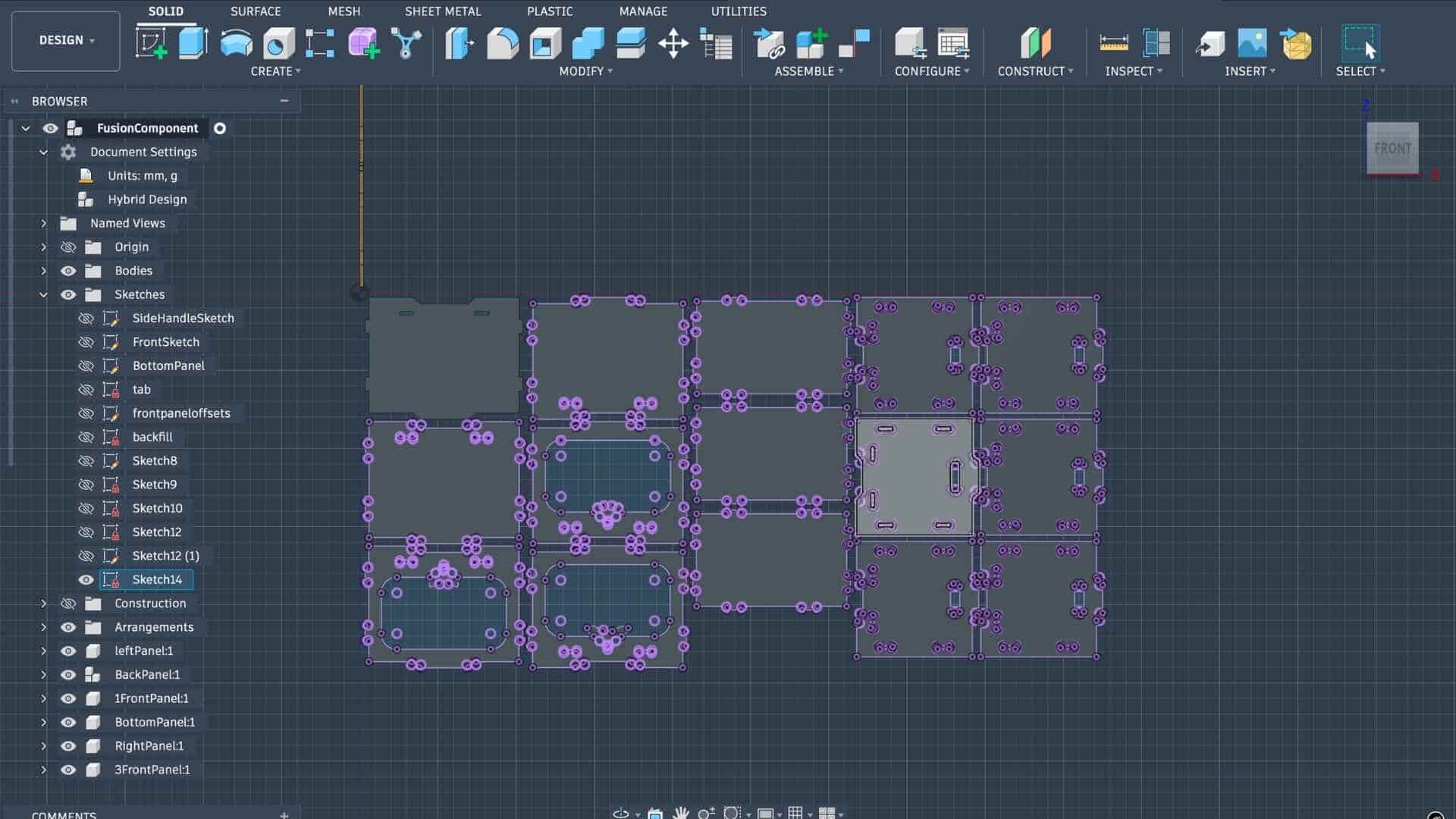
Once the design of a single unit was complete, I converted the bodies into components and duplicated the necessary components to create three complete storage units. The next step was to arrange all parts for fabrication.
Nesting Process
For this, I used the nesting process to place all components within the dimensions of the plywood sheet available for machining. The plywood sheet measured 8 feet by 4 feet, and I found that three storage units could fit efficiently within this sheet size. In total, the layout contained 15 components.
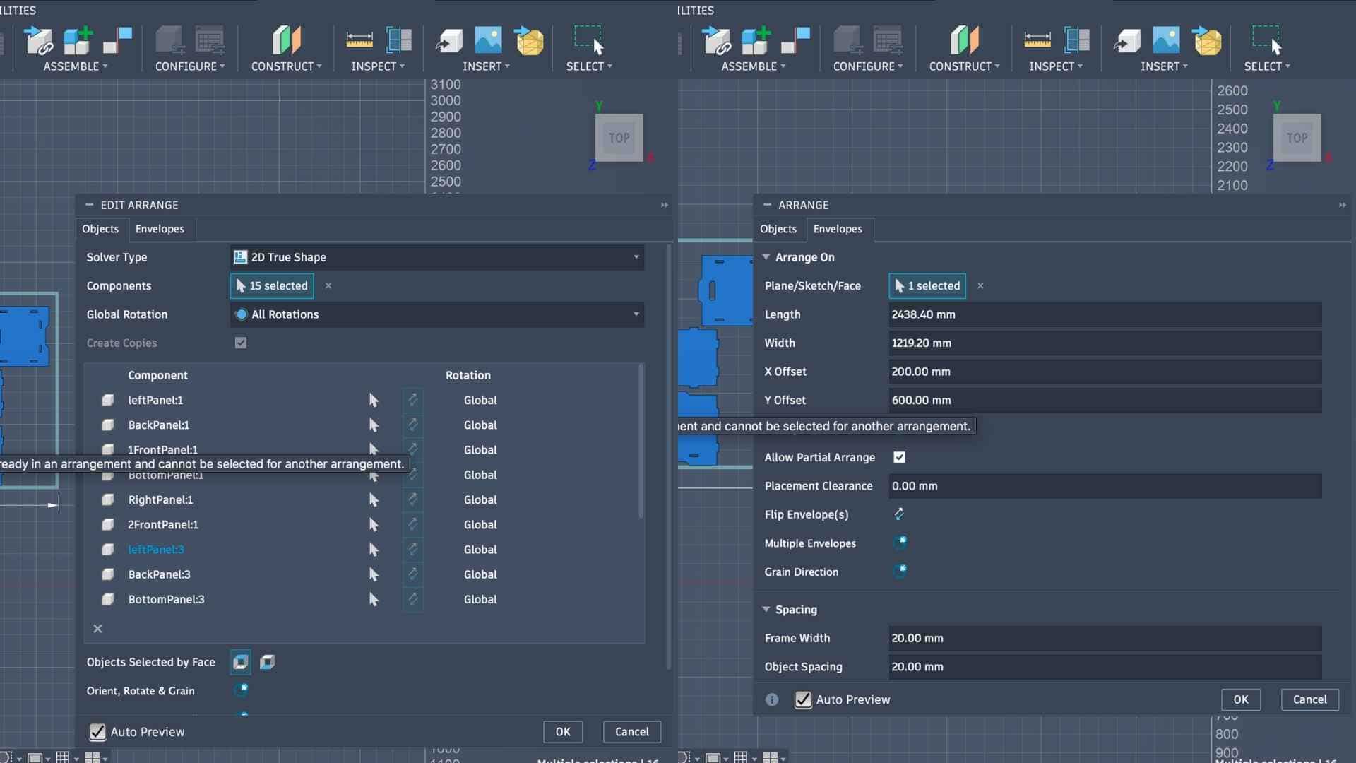
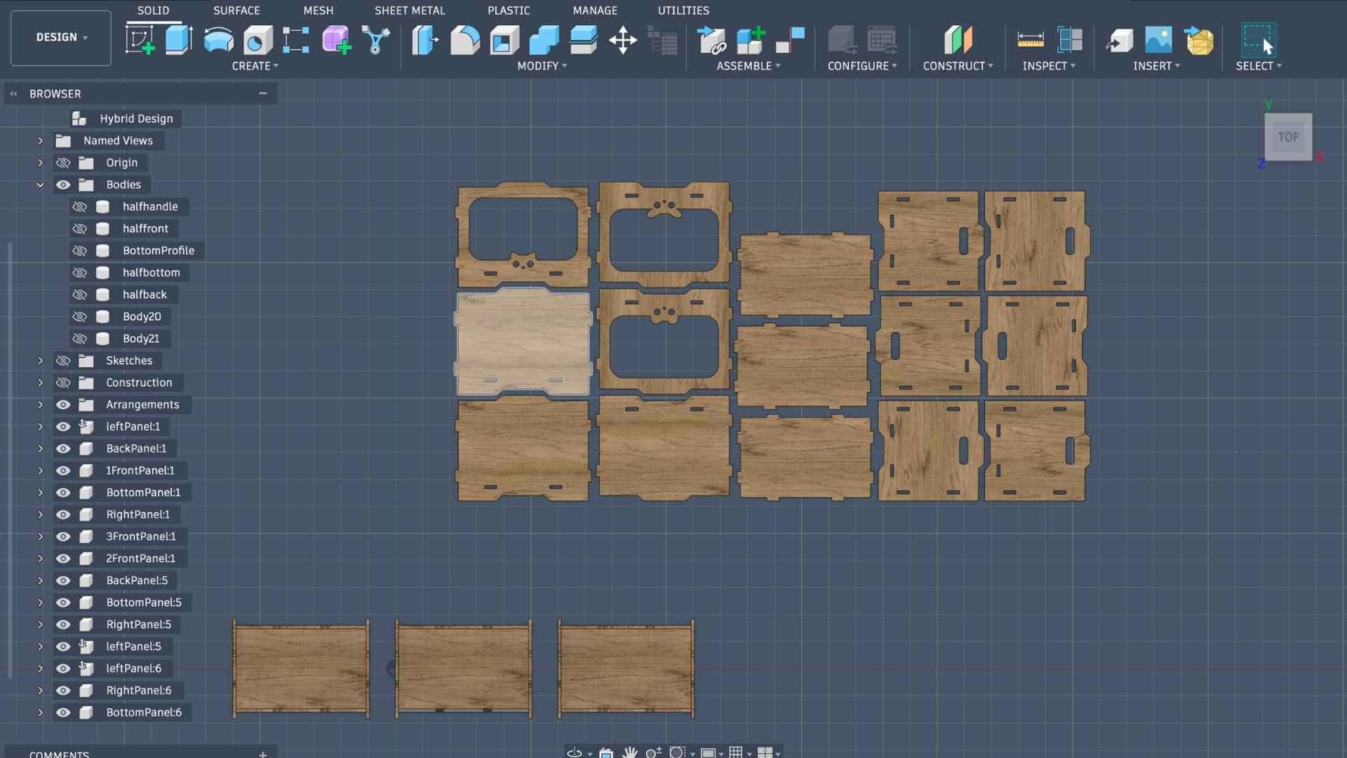
The nesting parameters were set with the sheet dimensions matching the plywood size, a frame margin of 20 mm, and a spacing of approximately 17 mm between parts. The arrangement maximized the use of the material, leaving very little unused space on the sheet.
Laser-cut Cardboard Joinery Test Piece
Before proceeding with CNC machining on the ShopBot, it is important to test the joinery and assembly to ensure that the design fits properly and functions as intended. Since CNC milling consumes more time and material, performing a quick prototype test helps identify potential issues in advance.
For this stage, I created a laser-cut test prototype using cardboard to evaluate the joinery of the modular storage unit. A sheet of 3 mm cardboard available in the lab was used for this purpose. The workflow followed the same process documented earlier during Week 3, where laser cutting was introduced. The design was exported as a DXF file, opened in Inkscape, and prepared for laser cutting using the cardboard cutting parameters established during the Week 3 group assignment.
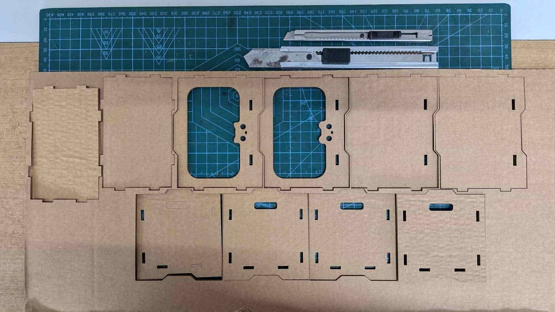
Because the original design was created for 12 mm plywood, some adjustments were required for the cardboard prototype. The material thickness parameter was updated to approximately 2.6 mm, accounting for the compression and layered structure of the cardboard. After updating the parameter, the model was scaled and regenerated so that the joinery matched the new material thickness.
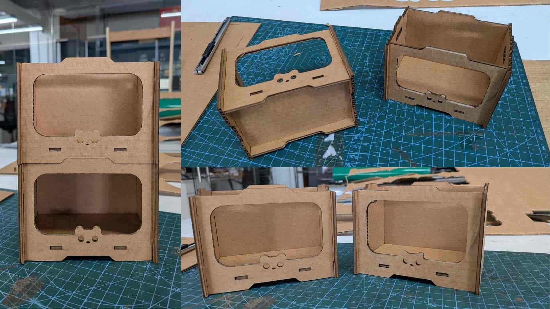
Once the updated design was prepared, the components were laser cut in cardboard at the lab. After cutting, the parts were assembled to test the fit and functionality of the joints. The prototype resembled a miniature version of the final storage unit, allowing me to quickly verify that the tabs and slots aligned correctly.
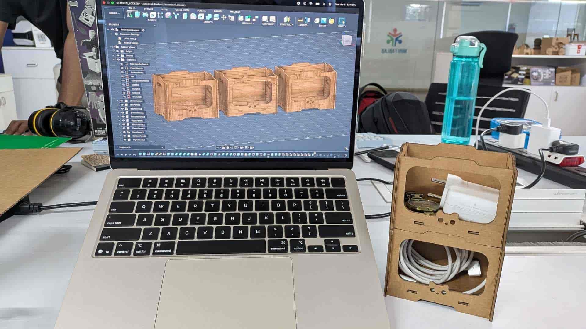
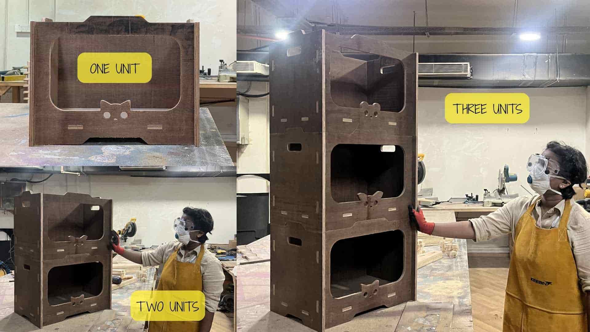
To further evaluate the concept, I stacked multiple units, confirming that the modular storage system could be arranged vertically as intended. The prototype proved to be quite practical for organizing small desk items such as chargers, cables, and a watch, keeping them neatly separated while working.
Since the joinery fit well and the structure assembled successfully, the design was validated and ready to move forward to the CNC machining stage using the ShopBot.
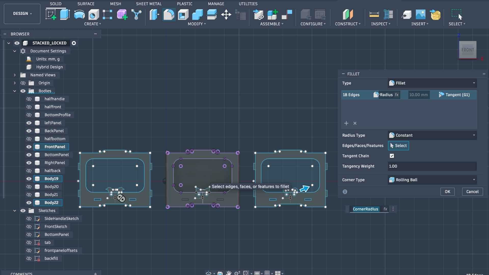
Adding Dogbone
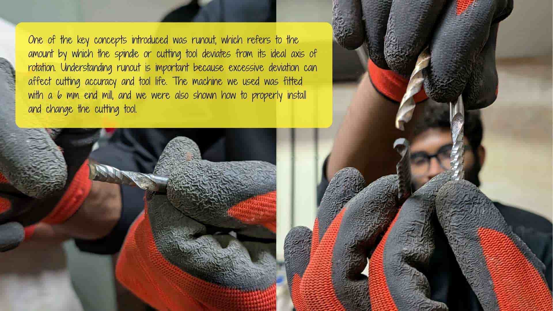
Before preparing the design for CNC machining, it is necessary to add dogbone fillets to the internal corners of the slots. In CNC routing, the cutting tool is round, which means it cannot produce perfectly sharp 90-degree internal corners. In our case, the cutting tool used is a 6 mm end mill, which leaves a small radius at internal corners. This radius can prevent square-edged parts, such as tabs or tenons, from fitting properly into slots or mortises.
To solve this issue, dogbones are added. A dogbone is a small circular relief cut placed at the internal corners of a slot or pocket. This allows the mating part to fit completely into the corner despite the round cutting tool.
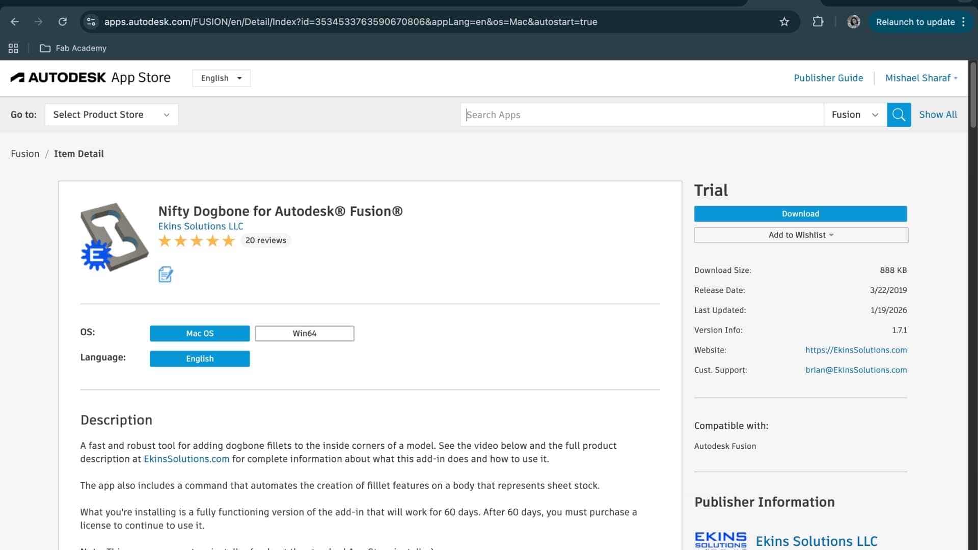
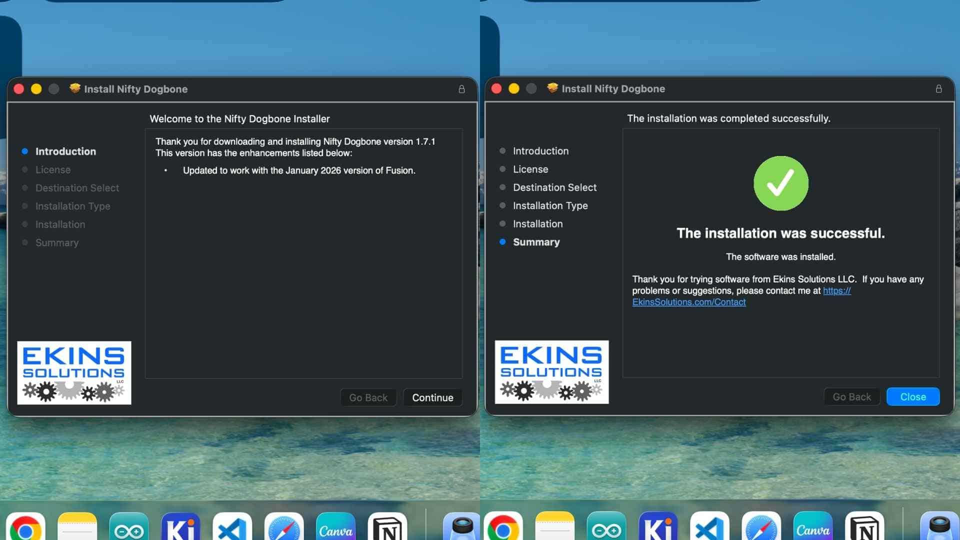
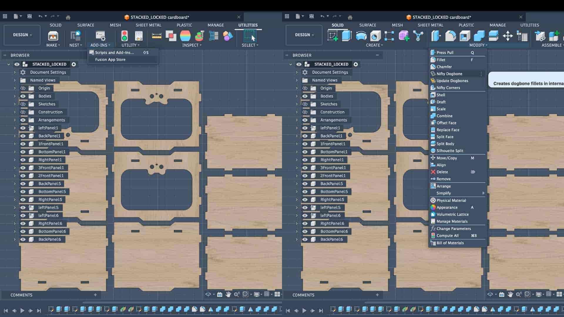
To create these dogbones, I installed a plugin from the Autodesk Fusion App Store called Nifty Dogbone for Autodesk Fusion. I downloaded the macOS version (trial) and installed it in Fusion. After installation, the tool appeared under the Modify menu as Nifty Dogbone.
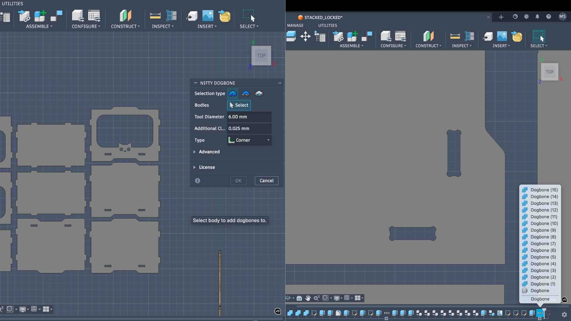
Using this tool, I set the tool diameter to 6 mm, matching the diameter of the end mill that would be used for machining. I then selected the faces of the bodies where slots were present, and the plugin automatically generated the dogbone fillets at the internal corners.
Checking Material Thickness
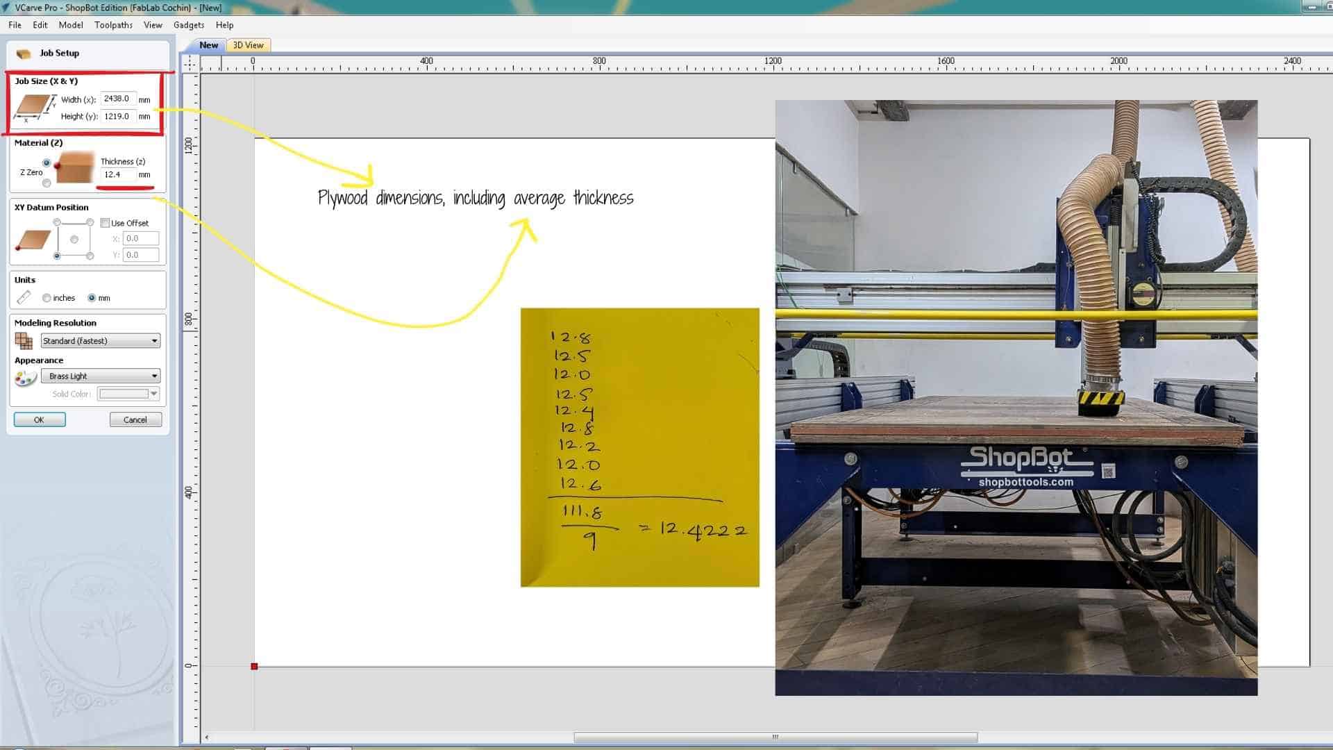
Before exporting the design for CNC machining, it is also important to verify the actual thickness of the plywood sheet. Although the design was initially created with a thickness parameter of 12 mm, plywood sheets often vary slightly in thickness across different areas of the sheet.
To account for this variation, I measured the thickness at multiple points on the plywood sheet using a vernier caliper. The measurements were then averaged to obtain a more reliable thickness value. In this case, the average thickness of the sheet was 12.4 mm.

After obtaining this value, I updated the material thickness parameter in the Fusion model so that the joinery would match the actual material thickness.
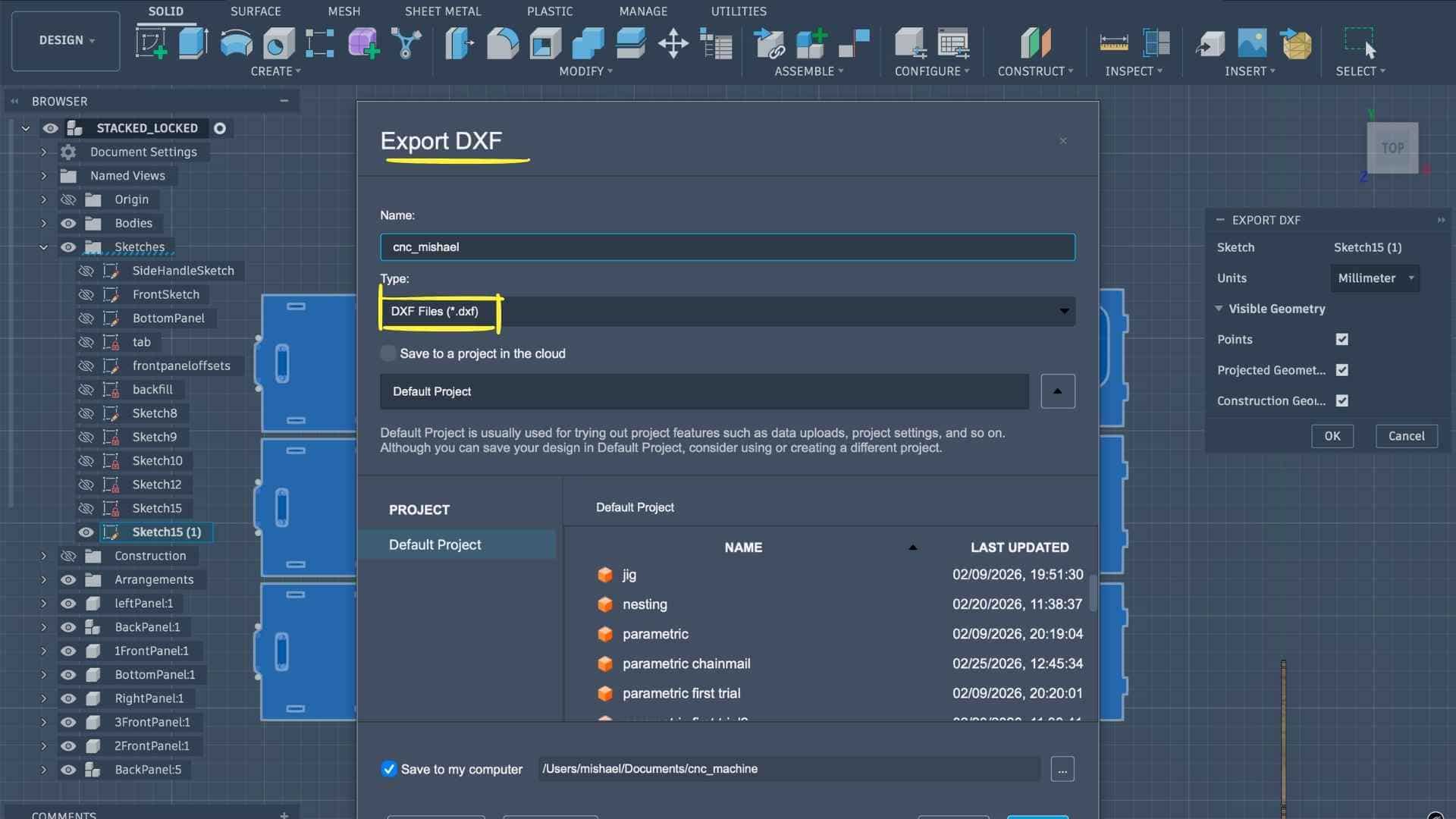
Exporting for CAM
Once the thickness parameter was updated, I created a new sketch, projected the required profiles, and exported the geometry as a DXF file. This file would be used in the next step to prepare the CAM toolpaths for machining on the ShopBot CNC router.
Preparing the Machining Setup in VCarve
To prepare the design for CNC machining, I used VCarve Pro – ShopBot Edition, a CAD/CAM software specifically designed for ShopBot CNC machines. This software is used to generate the toolpaths that the machine will follow during the milling process.
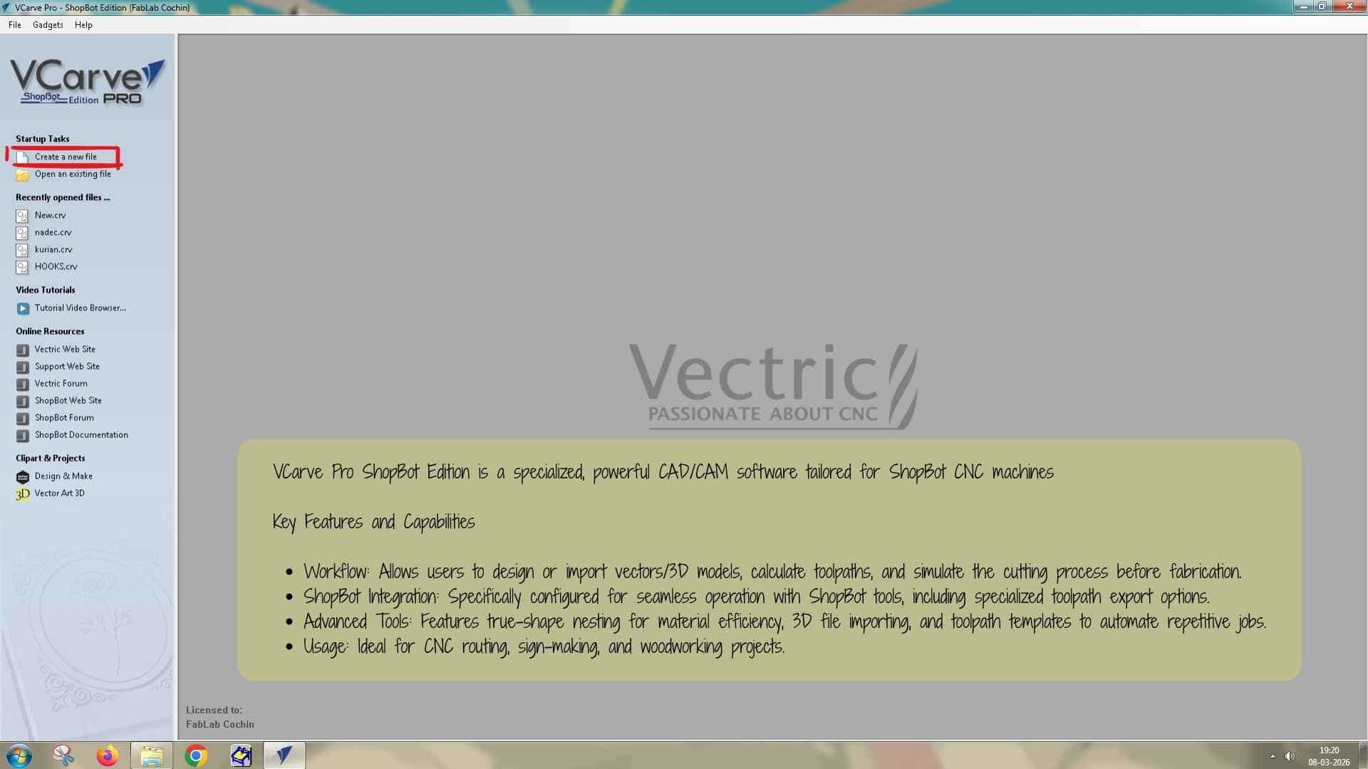
After opening VCarve, I created a new file and set the job size according to the dimensions of the plywood sheet being used. The sheet size was 8 ft × 4 ft, which corresponds to approximately 2438 mm × 1219 mm. The material thickness was set to 12.4 mm, based on the average measurement obtained earlier from the plywood sheet. After entering these values, the workspace was created.
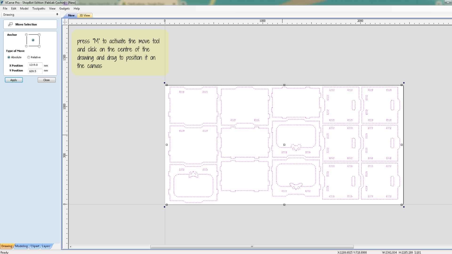
Next, I imported the design by going to File → Import Vectors and selecting the DXF file exported from Fusion 360. Sometimes the imported geometry does not appear centered on the workspace. To reposition it, the drawing can be selected and the Move tool can be activated by pressing M, allowing the design to be dragged and placed correctly within the working area.
Planning Screw Locations
Before generating the cutting toolpaths, the plywood sheet must be secured to the machine bed. On the ShopBot machine, a sacrificial layer of wood is already placed on the bed, and the plywood sheet is positioned on top of it. The sacrificial layer allows the cutting tool to go slightly deeper than the material thickness without damaging the machine bed.
The plywood sheet needs to be screwed down to the sacrificial layer so that it does not move during machining. However, screws cannot be placed in areas where the cutting tool will travel, because if the end mill collides with a screw it can break the tool.
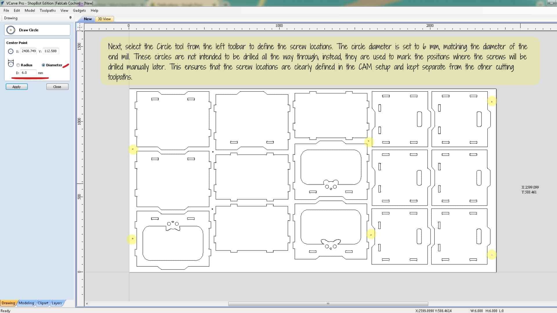
To mark safe screw locations, I created small circular vectors in areas where the toolpath would not pass. These circles were drawn with a diameter of 6 mm, matching the diameter of the end mill.
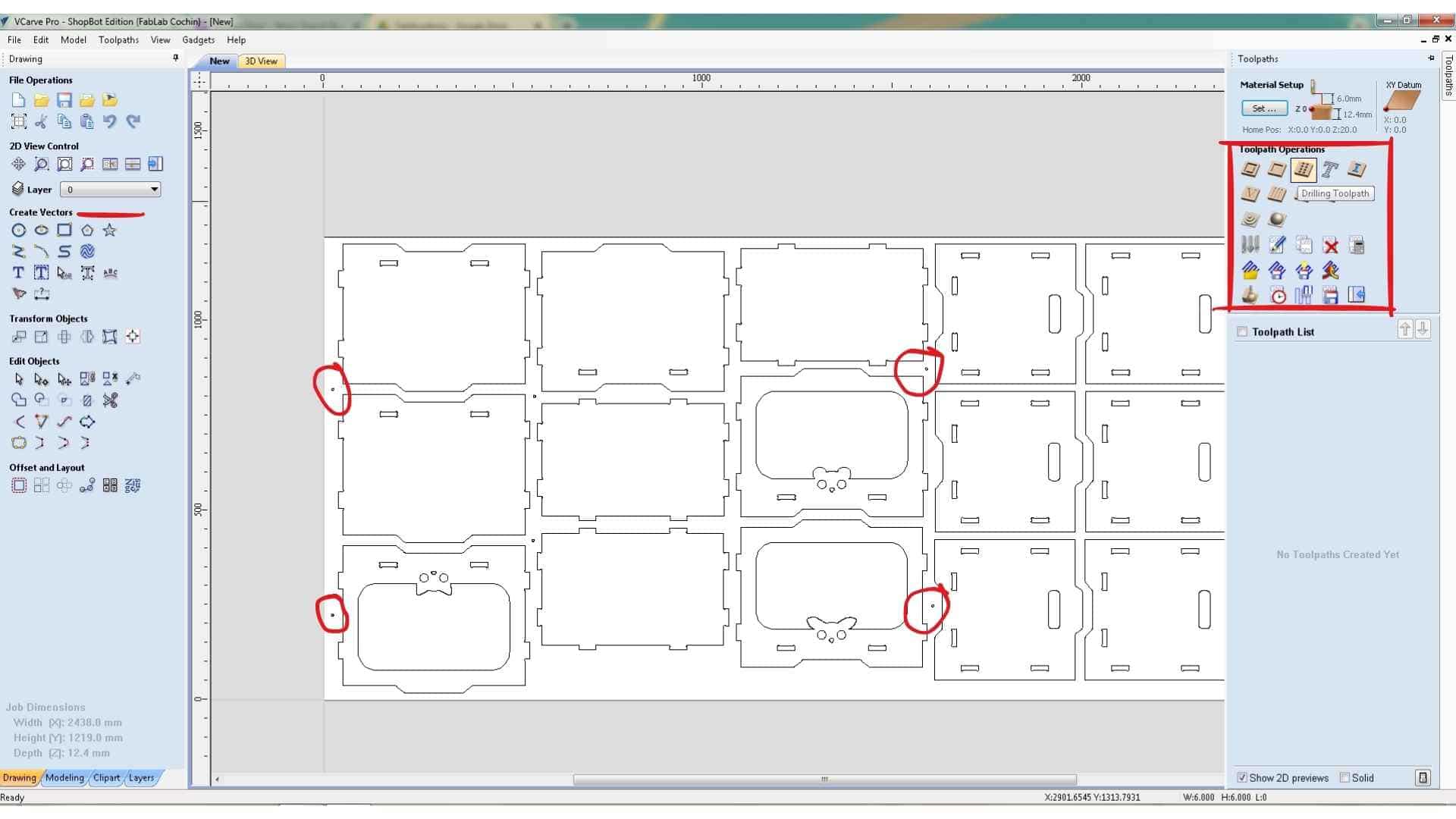
A drilling toolpath operation was then created in VCarve. The drilling operation was applied to these circles, but the depth was kept shallow so that the machine would only mark the positions rather than drill through the material. These marks serve as guides for manually drilling holes later, after which screws can be inserted to secure the sheet to the sacrificial layer.
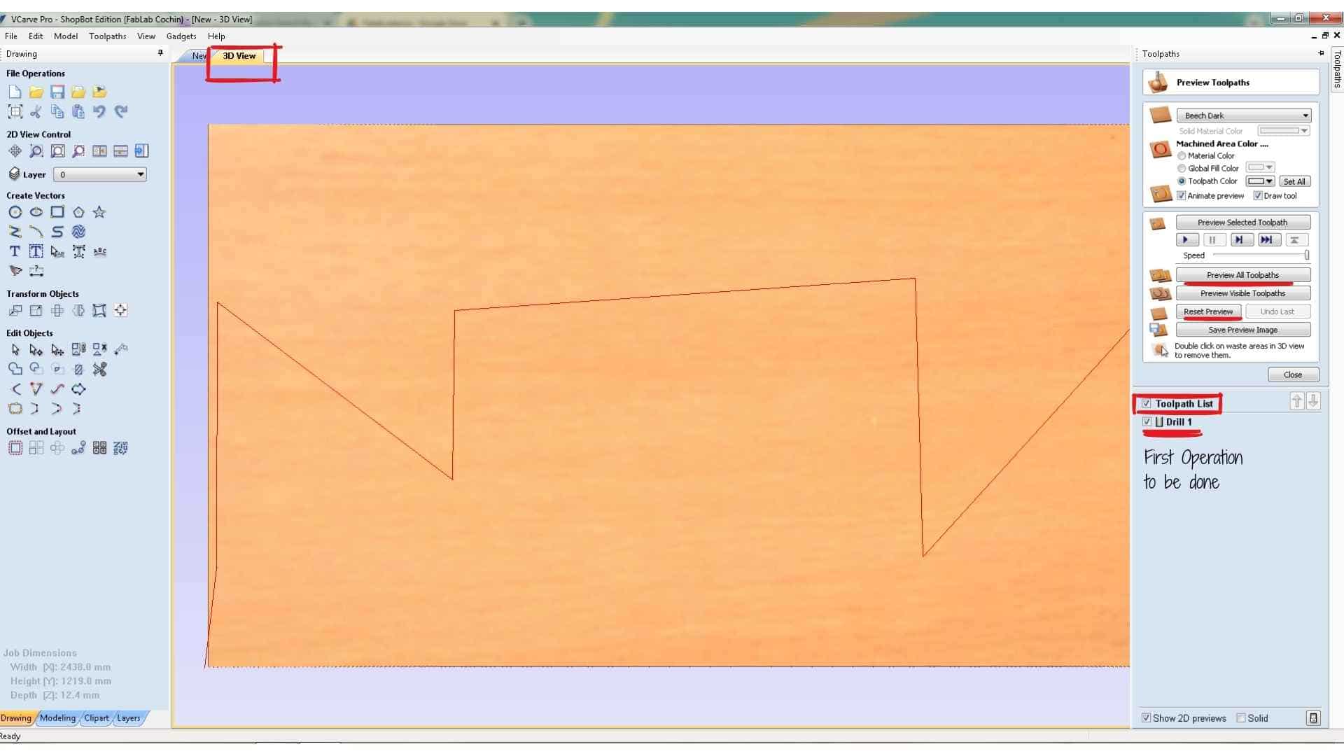
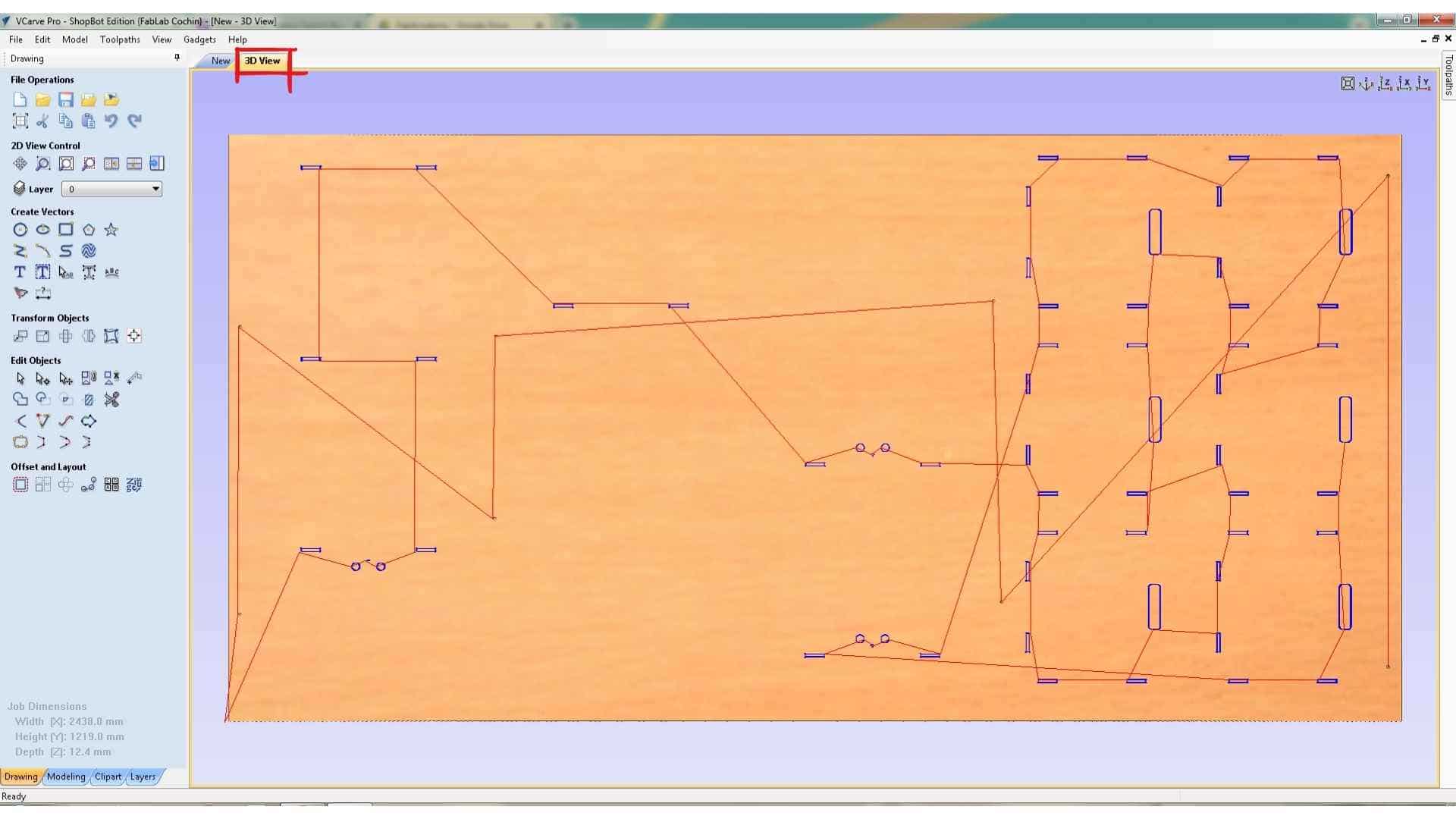
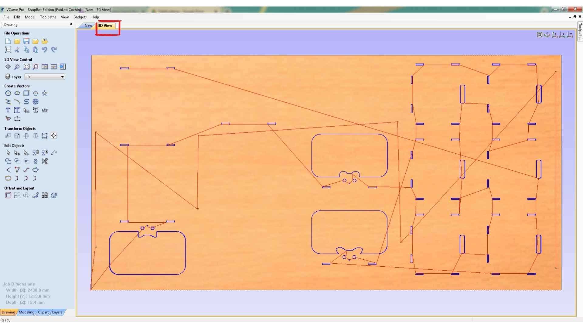
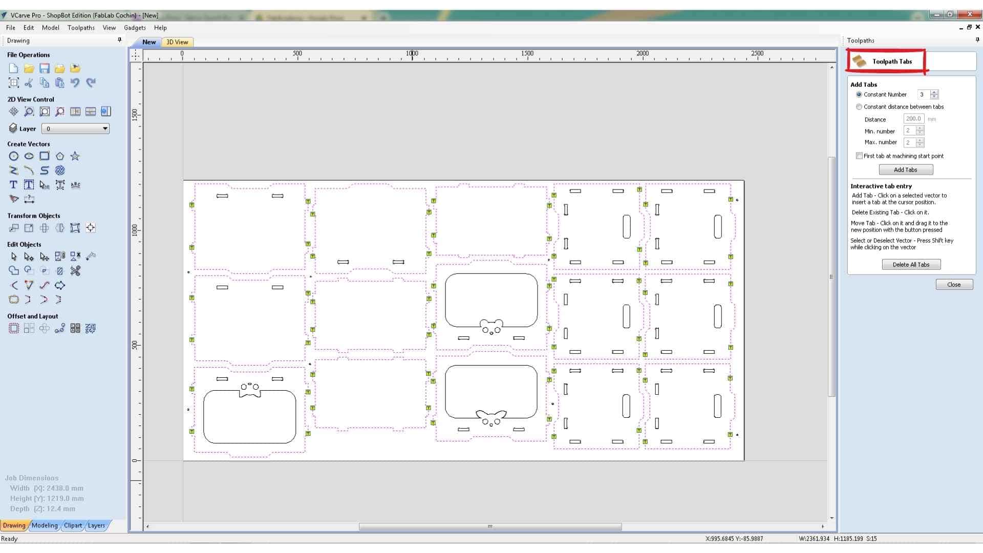
The toolpath preview can be viewed in two tabs:
Creating the Slot Cutting Toolpath
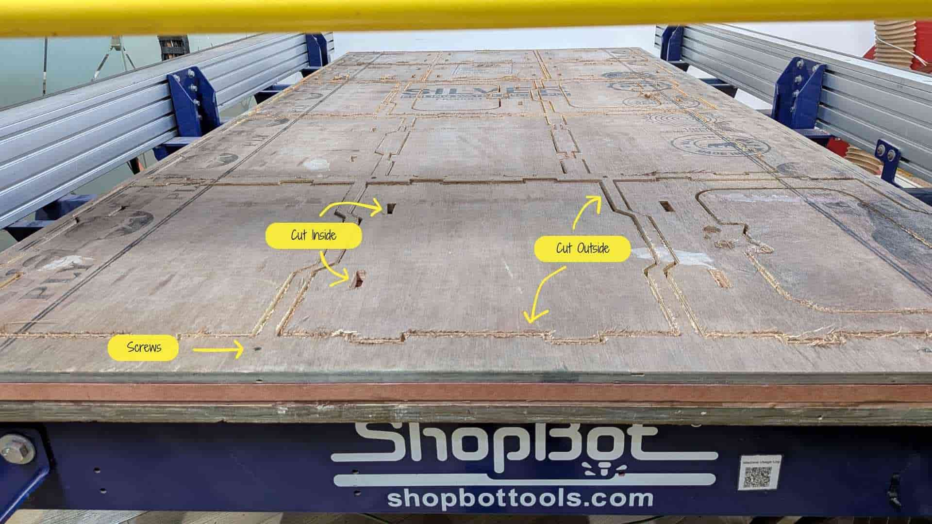
The second operation was the Profile Toolpath used to cut the internal slot features of the design. For this step, the slot vectors were selected and the machining option was set to Inside Cut, ensuring that the tool moves along the inner side of the vector so the slot dimensions remain accurate.
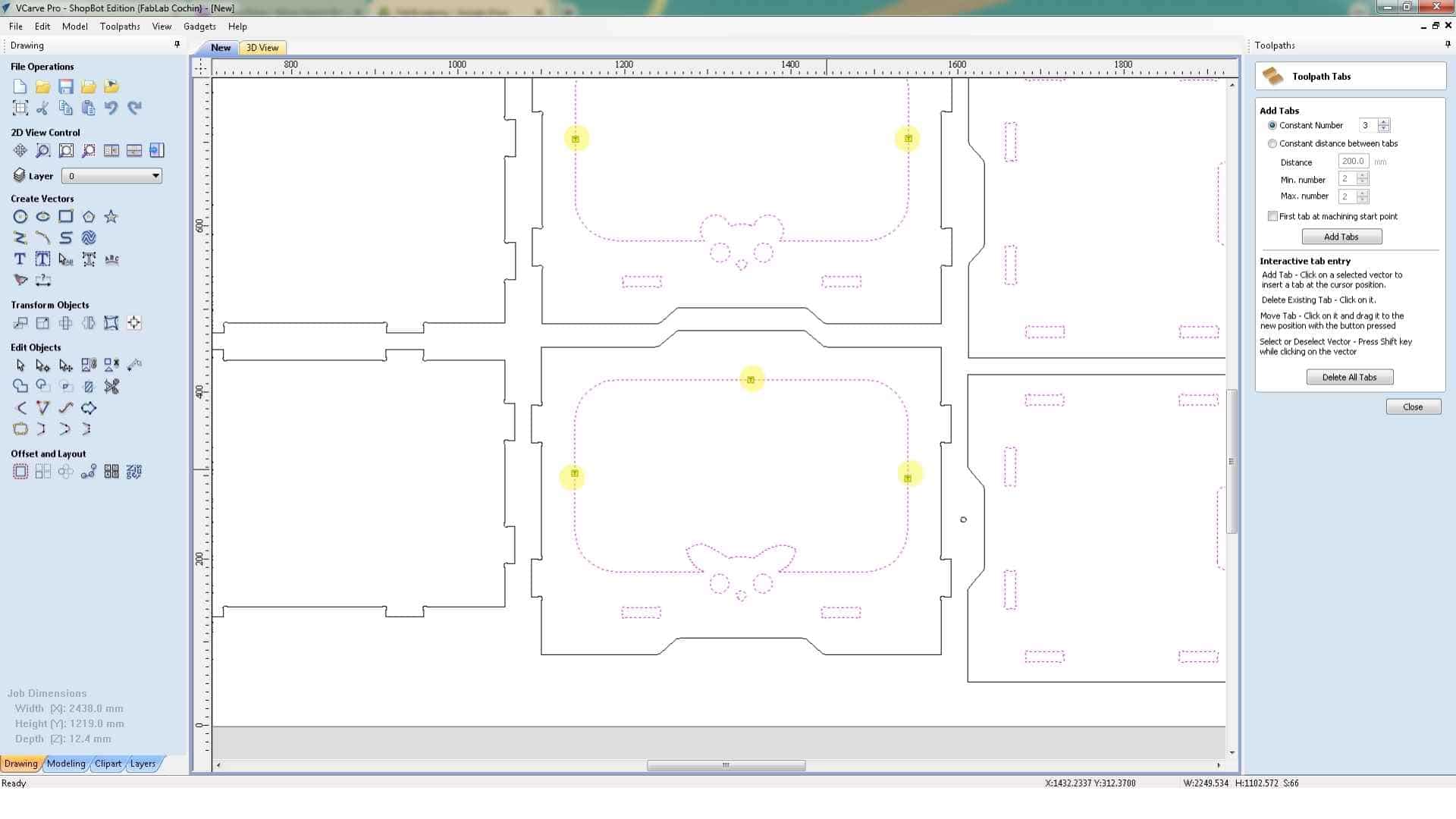
Some of the larger internal areas were also given holding tabs to prevent pieces from loosening during machining.
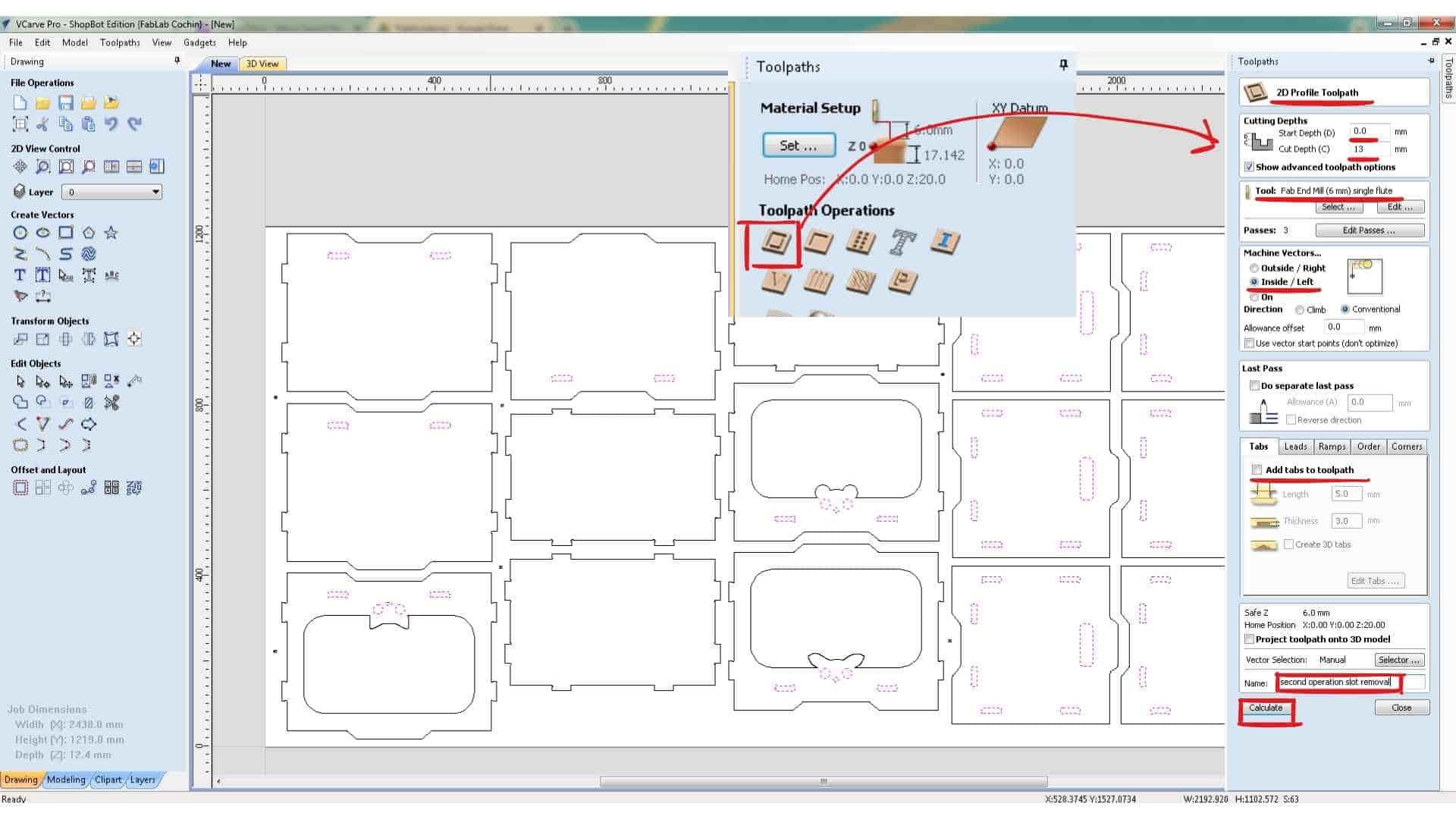
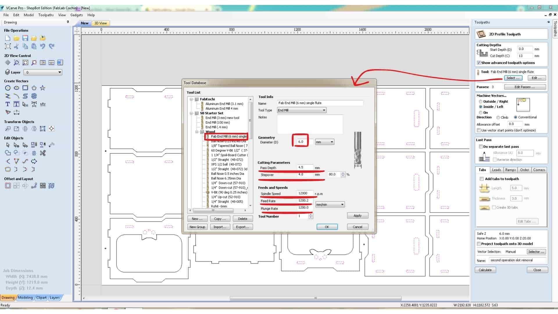
The tool used was a 6 mm single-flute end mill, with the feed rate set to 1200 mm/min. The start depth was set to 0 mm, since the tool begins cutting from the surface of the material. The cut depth was set to 13 mm, which is slightly deeper than the actual material thickness of 12.4 mm. This ensures the tool cuts completely through the plywood and slightly into the sacrificial layer, preventing incomplete cuts caused by small thickness variations in the material.
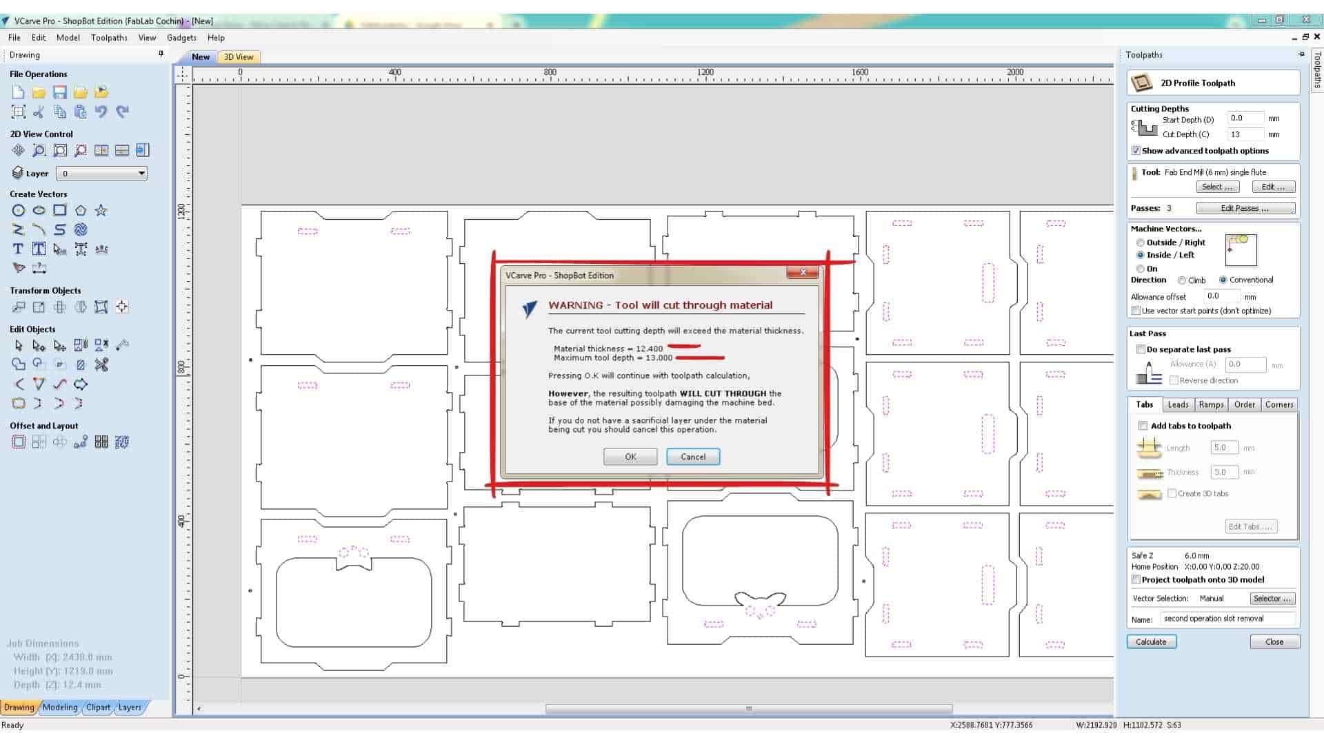
When calculating the toolpath, VCarve displays a warning indicating that the cut depth exceeds the material thickness. Since this was intentional, the warning was accepted and the toolpath preview was generated.
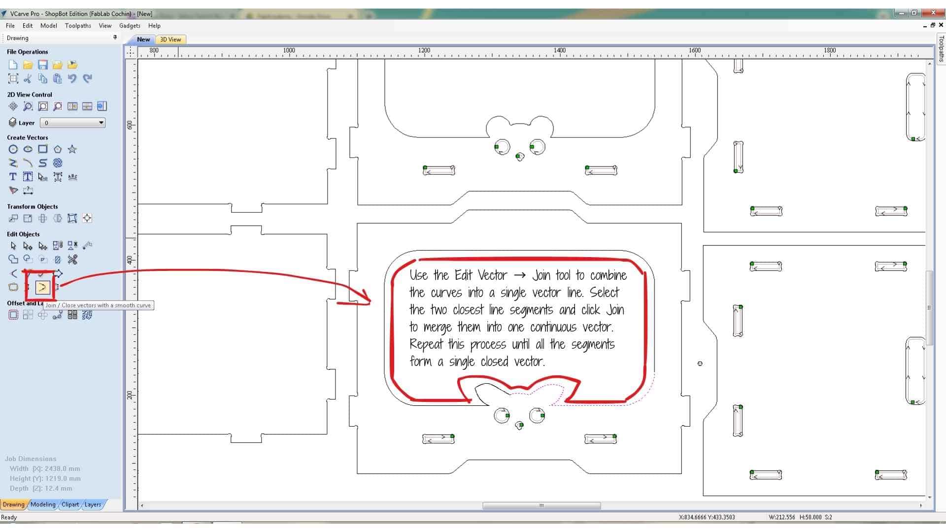
During this step, I noticed that some vectors had not been selected correctly. This was because certain curves in the animal ear profiles were not joined into continuous vectors. To fix this, I used the Join tool to combine adjacent line segments into single closed vectors. This ensures that the CNC machine treats the geometry as a single path instead of multiple separate segments.
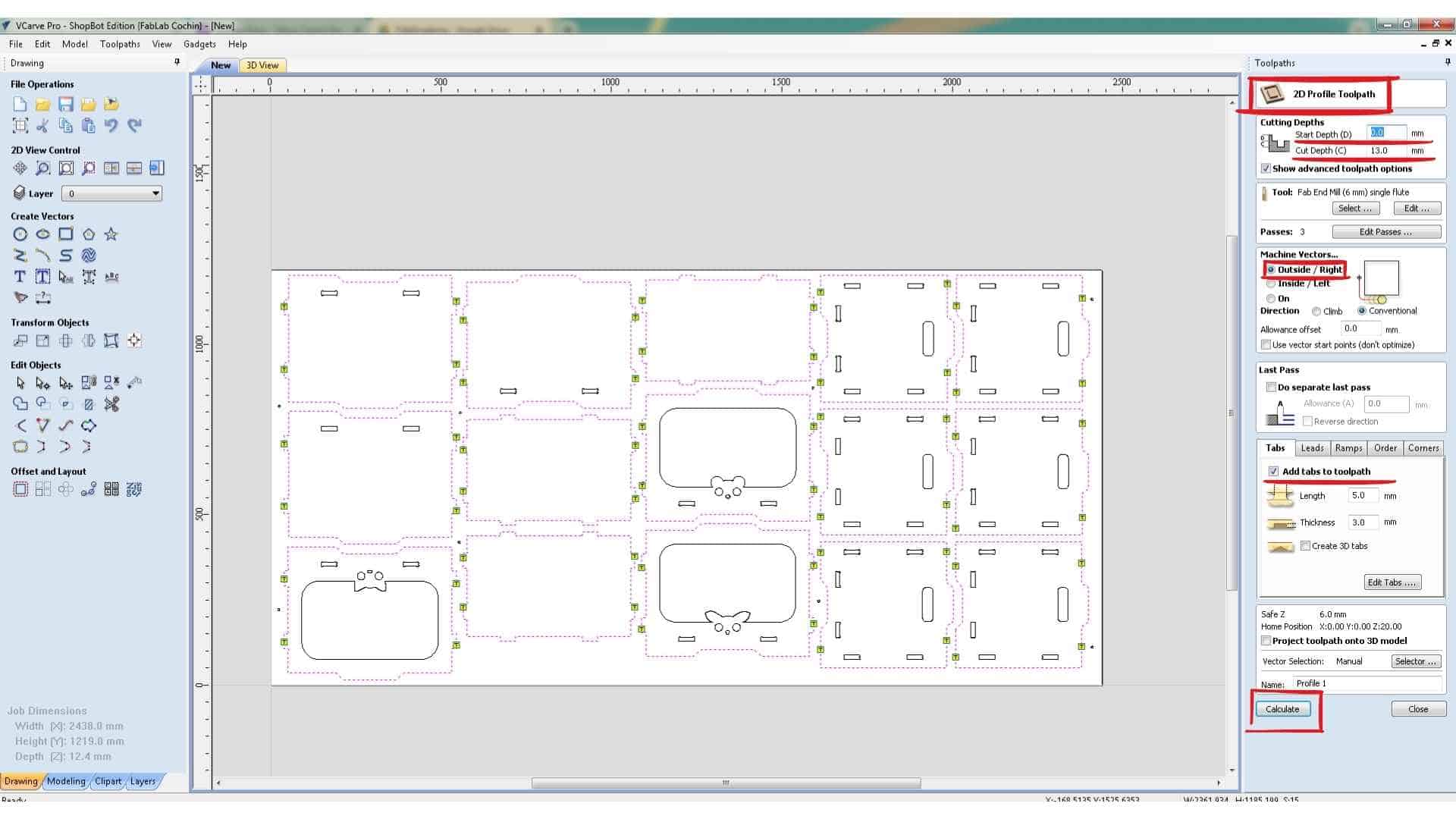
Cutting the Outer Profile
The final operation was cutting the outer profile of each component. This was again created using a Profile Toolpath, but this time the machining option was set to Outside Cut, ensuring that the tool cuts along the outside of the vector so that the final part dimensions remain accurate.
Holding tabs were added to these outer profiles to keep the parts attached to the sheet during machining. Without tabs, the parts could move or shift once they are fully cut.
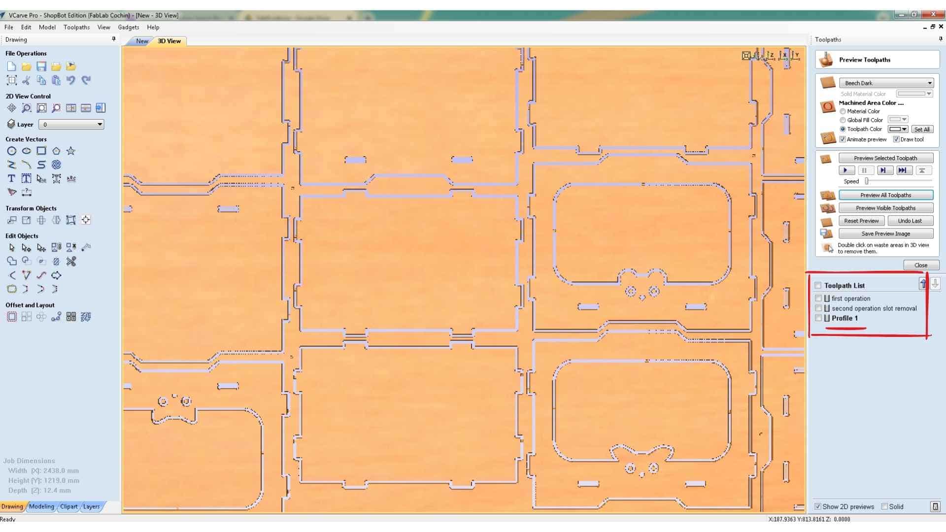
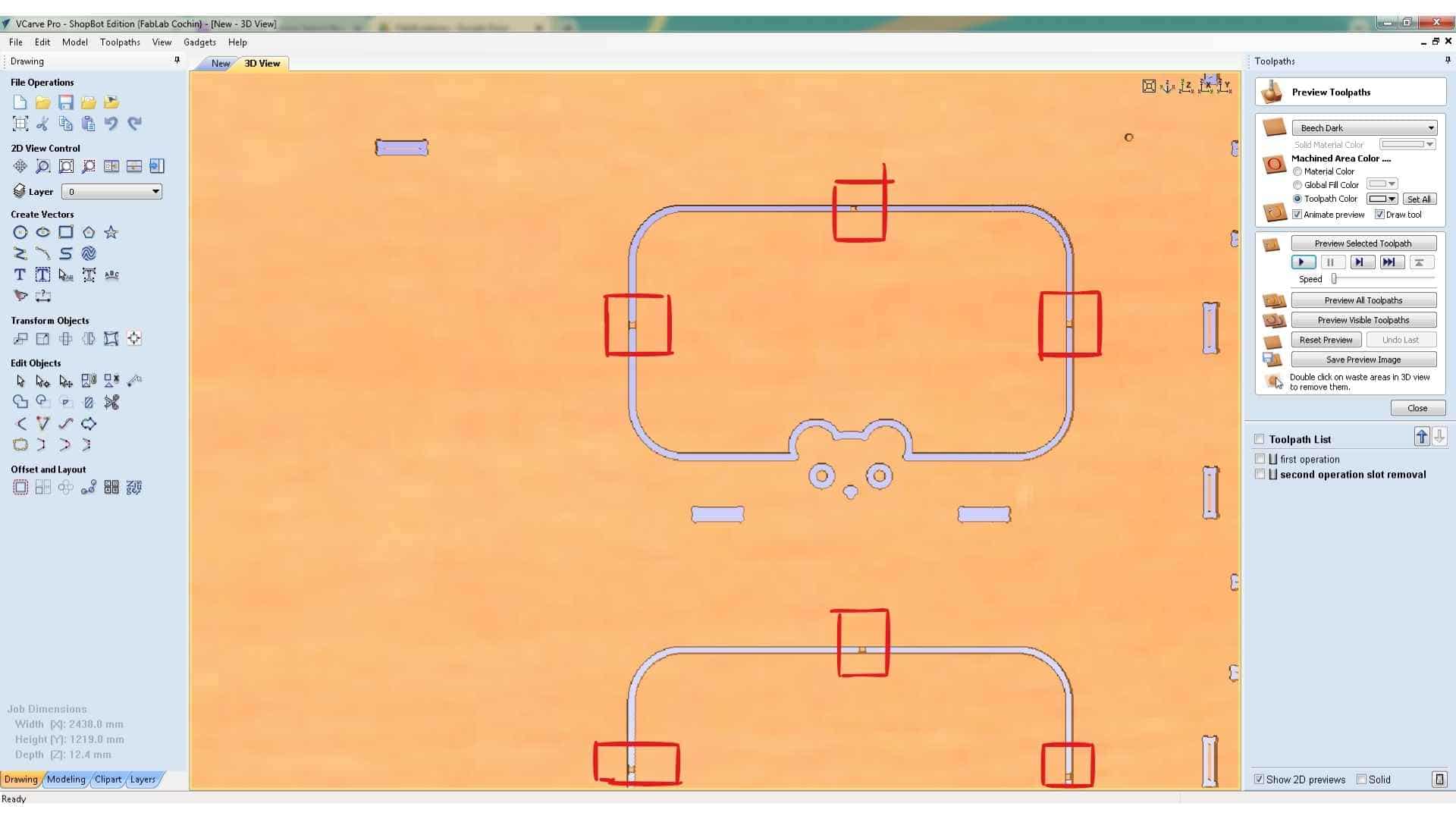
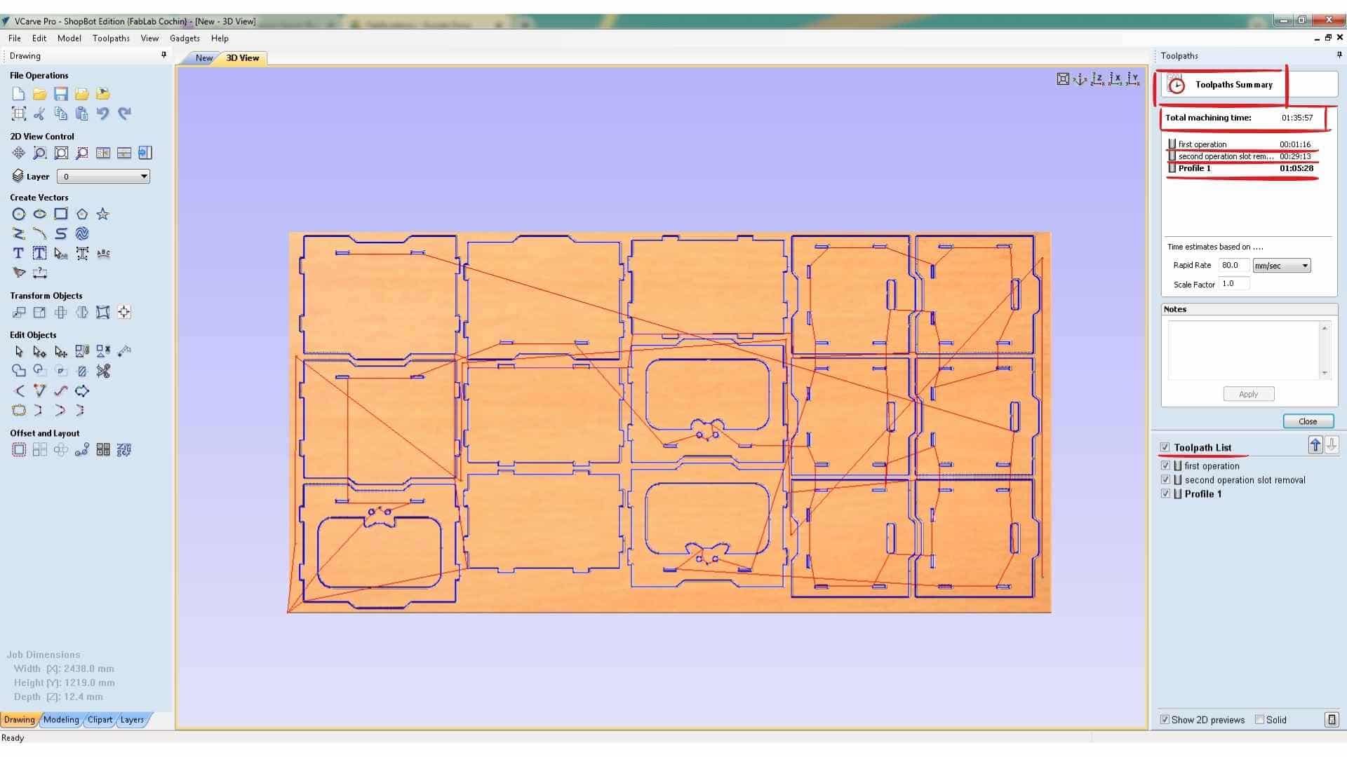
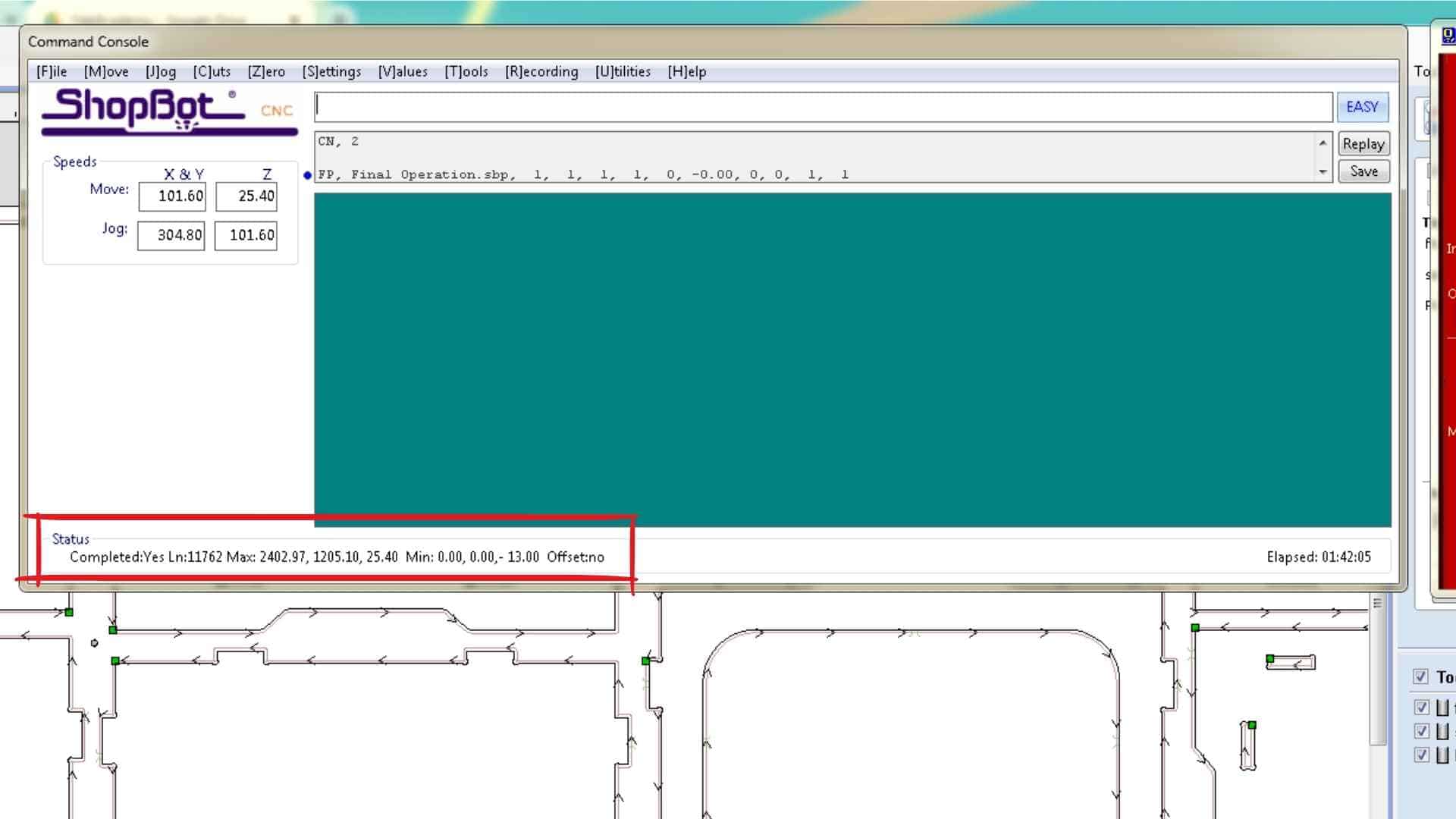
After calculating the toolpath, the preview showed the full machining sequence. The estimated machining time for the complete job was approximately 1 hour and 35 minutes.
Saving the Toolpaths
The toolpaths were exported as ShopBot Part Files (.SBP). The operations were saved as two separate files.
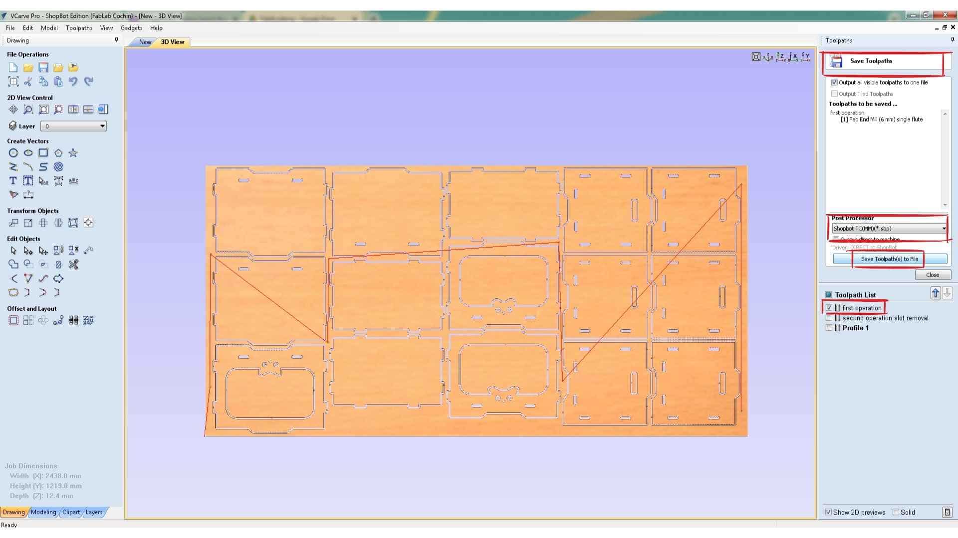
The first file contains the drilling operation, which marks the screw positions. After running this file on the machine, the holes are manually drilled and screws are inserted to secure the plywood sheet to the sacrificial layer.
The second file contains the remaining operations: the internal slot cutting and the outer profile cutting. Saving them separately ensures that the machining operations will not accidentally pass over the screw locations during cutting, which helps prevent tool collisions and possible end mill breakage.
Running the Job on the ShopBot CNC
After completing the CAM preparation in VCarve, the next step was to run the job using the ShopBot command console. This interface allows control of the CNC machine and displays the X, Y, and Z axis positions, as well as the code that the machine executes during operation.
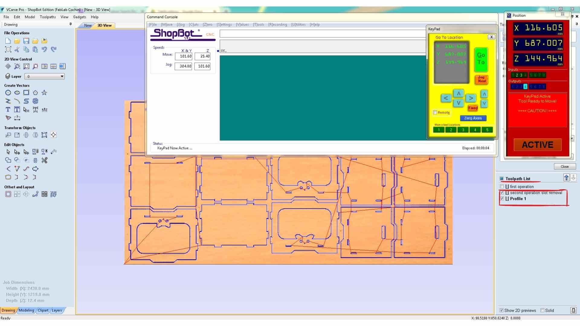
The first step before running any job is to set the origin (zero position) of the machine. Since a new plywood sheet had been placed on the machine bed, the origin used in the previous job would no longer be valid. Therefore, the machine coordinates needed to be reset.
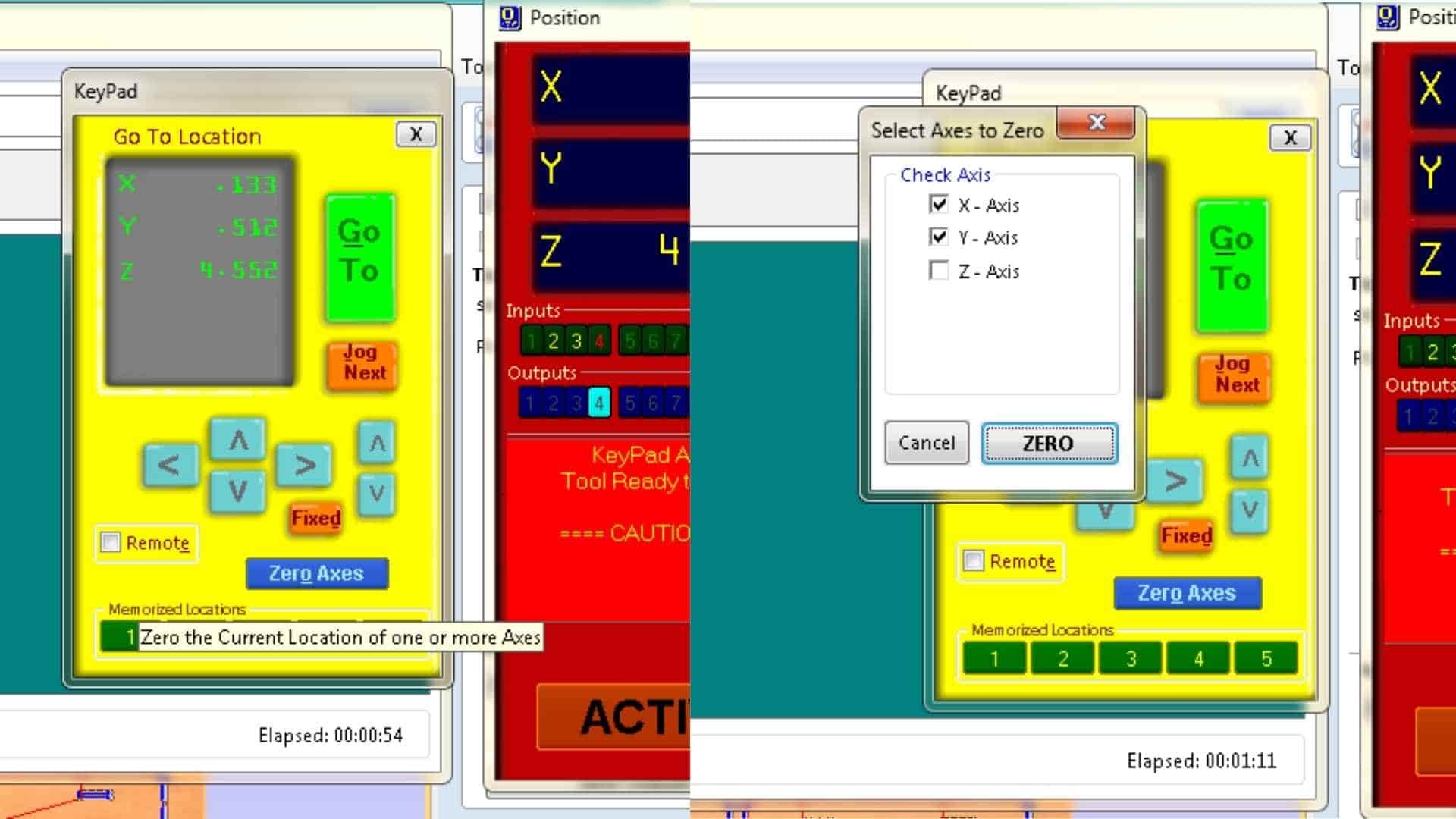
To set the X and Y origin, the movement controls on the right side of the ShopBot console were used. These appear as a yellow keypad interface that allows manual movement of the spindle across the bed. The same movement can also be controlled using the arrow keys on the keyboard. Using these controls, the spindle was moved to the desired reference point on the plywood sheet. Once the correct position was reached, the X and Y axes were zeroed, defining the starting point for the machining process.
Setting the Z-axis origin requires a slightly different process. The ShopBot machine uses a touch-off system consisting of an aluminum plate and an alligator clip. The aluminum plate is placed directly beneath the cutting tool, and the alligator clip is attached to the end mill. When the tool touches the plate, it completes an electrical circuit that the machine can detect.
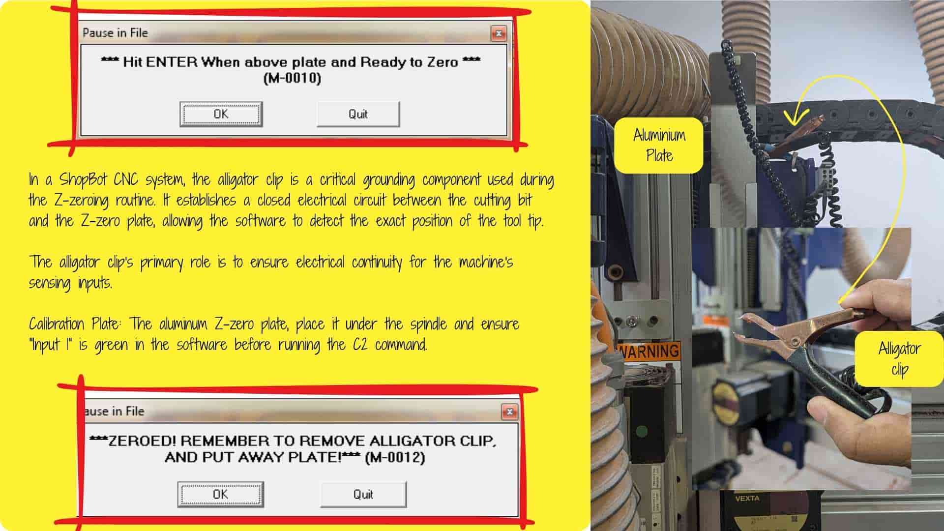
Once the plate and clip were connected, the Z-zeroing routine was started. The machine automatically lowered the bit until it touched the aluminum plate. It performs this action twice to confirm the measurement, ensuring an accurate Z-axis reference. After the process was complete, the aluminum plate and clip were removed. At this point, the machine origin for X, Y, and Z was correctly set.
Running the First Operation – Marking Screw Locations
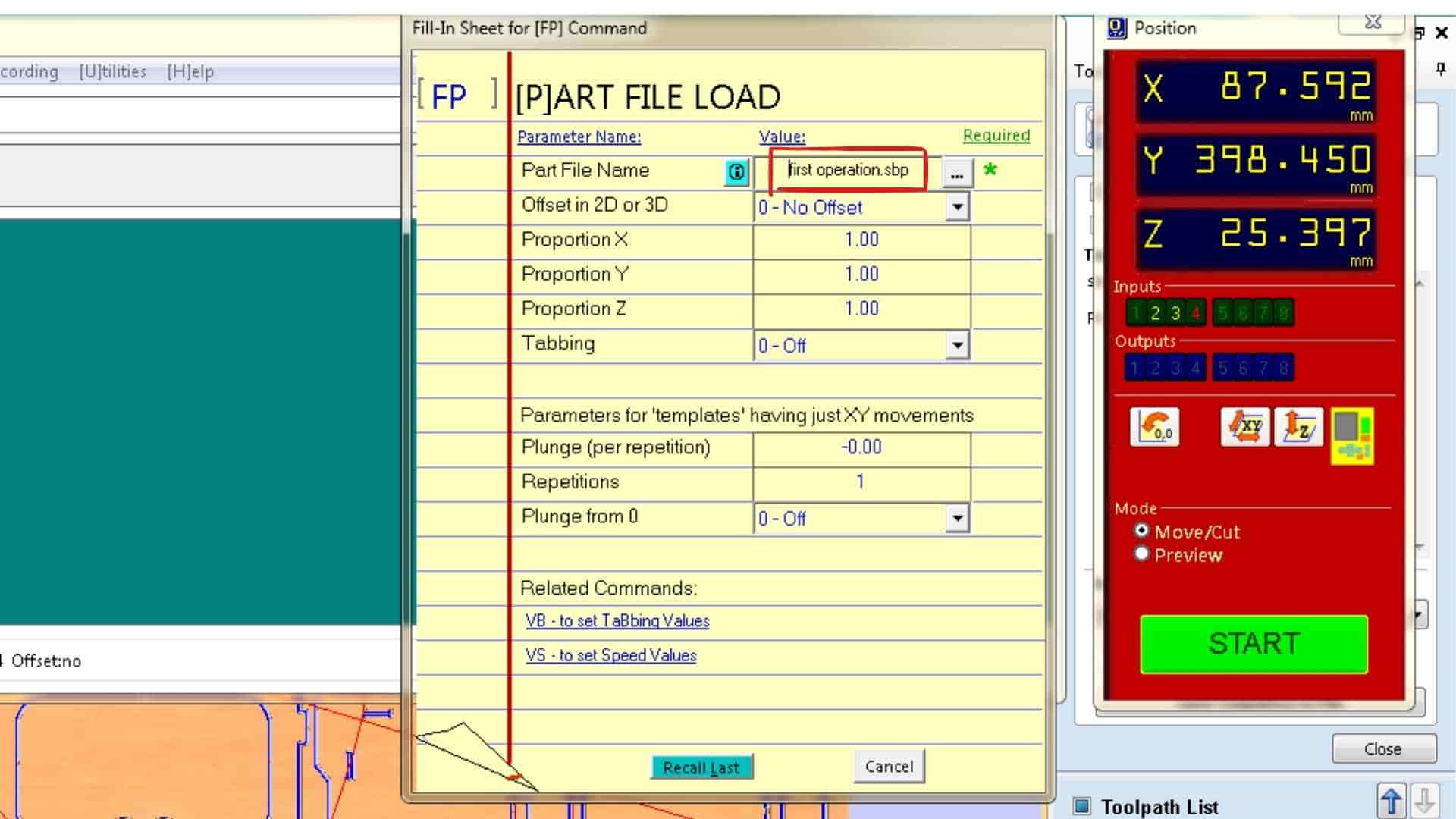
With the machine origin established, the first file generated in VCarve was loaded into the ShopBot software. This file contained the drilling operation used to mark the screw locations.
Before starting the job, the file name was verified to ensure that the correct operation was being executed. Once confirmed, the job was started from the console.
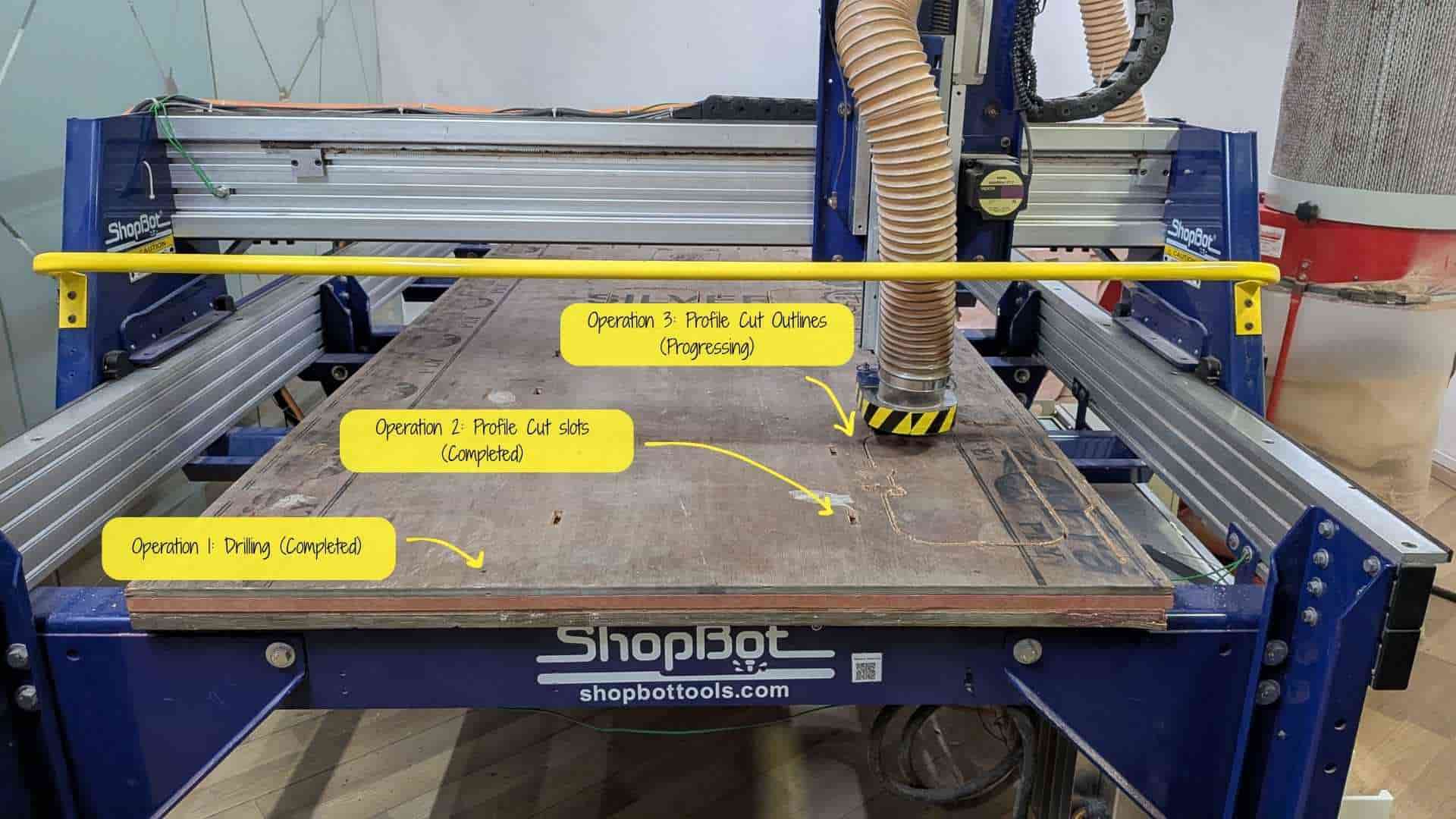
When running the machine, the spindle must be turned on manually using the spindle key. It is important to listen for the spindle sound to confirm that it is spinning correctly before proceeding. For this first operation, the vacuum system was intentionally kept off. This allowed the debris left by the drilling marks to remain visible, making it easier to identify the marked screw positions.
The machine then ran the drilling routine and created eight marked positions on the plywood sheet.
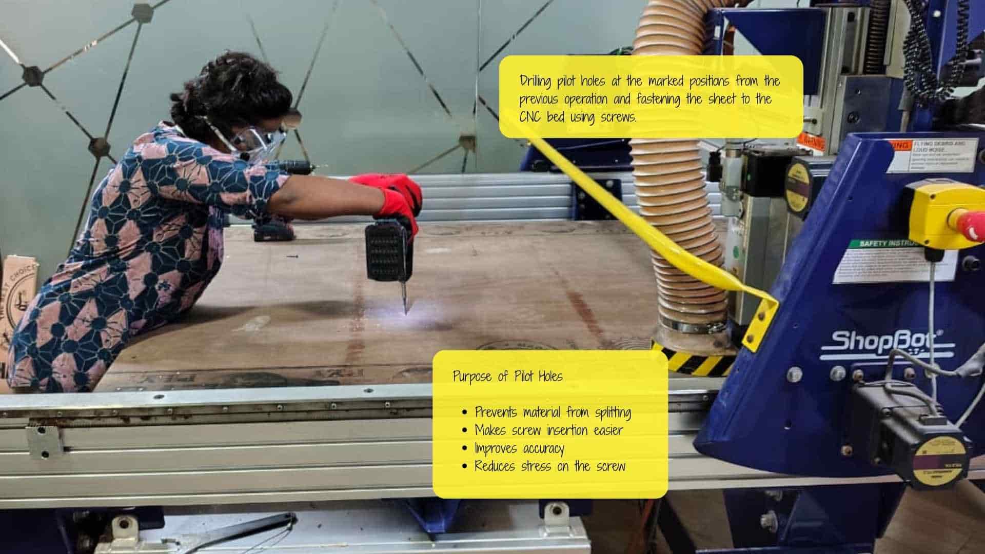
Once the operation was completed, the spindle was turned off. The marked positions were then manually drilled and screws were inserted, fastening the plywood sheet securely to the sacrificial layer underneath.
Resetting the Z Axis
After securing the sheet with screws, the Z-axis was reset again using the aluminum plate and alligator clip. This step ensures that any small changes in height caused by repositioning the sheet or tightening the screws do not affect the cutting depth during the next machining operations.
Running the Final Machining Operations
After resetting the Z-axis, the second file containing the remaining toolpaths was loaded. This file included both the internal slot cuts and the outer profile cuts.
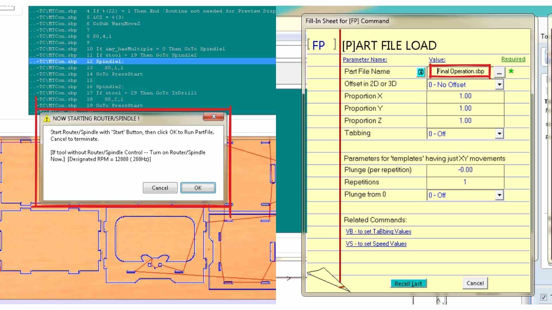
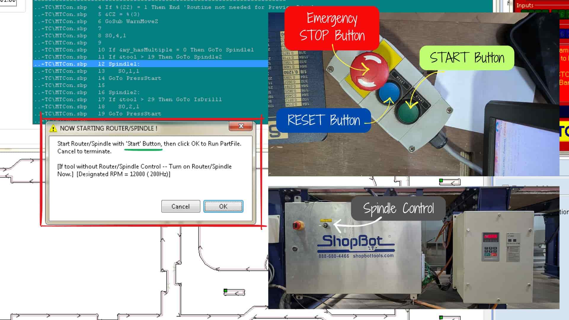
Once the file was loaded, the machine was prepared to begin cutting. The green start button on the machine was pressed to initiate the process. After confirming the job start, the spindle was turned on, followed by turning on the vacuum system, which removes dust and debris during cutting. The spindle controller displays a digital readout indicating that the spindle is active.
The machining process then began. According to the toolpath preview, the full job was expected to take approximately 1 hour and 30 minutes. The machine first completed the internal slot cuts, followed by the outer profile cuts that separated the parts from the sheet.
It was important to ensure that the first drilling operation was not included in this stage, since the screws were already in place. Running that operation again could cause the cutting tool to collide with the screws.
Monitoring the Machining Process
During machining, operators are required to remain in the room and monitor the machine continuously. Maintaining a safe distance while observing the process helps ensure that any issues, such as tool breakage, loose parts, or unexpected movements, can be addressed immediately.
The safety procedures followed during this process were previously discussed and practiced as part of the group assignment safety training.
Removing the Parts and Post-Processing
After the machining process was completed and the machine was safely turned off, the next step was to remove the workpiece from the ShopBot bed. First, the spindle was moved away from the work area, and the eight screws used to secure the plywood sheet were carefully removed.
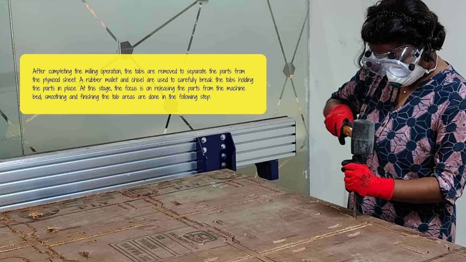
Once the sheet was free, the components still remained attached to the plywood because of the holding tabs that were intentionally added during the CAM stage. To separate the parts, a chisel and rubber mallet were used to break these tabs. At this stage, the focus was only on detaching the components from the sheet, not on finishing the edges. Surface finishing was carried out later during the post-processing stage.
After removing the parts, they were moved to the post-processing work table, while the ShopBot machine bed was vacuum cleaned to remove dust and debris. Cleaning the workspace ensures that the next user can safely load their material. In the lab, we followed the practice that the last person to use the machine cleans the work area and helps the next person set up their job. This not only keeps the workspace organized but also helps reinforce the workflow by observing and assisting in the setup process again. Throughout the machining process, our instructor supervised the work and provided guidance whenever needed, while still allowing us to carry out the operations ourselves.
Post-Processing the Components
Once the parts were removed from the sheet, they were taken to the post-processing area, where several finishing steps were carried out.
The first step was removing the remaining tab fragments using a rubber mallet and chisel. After this, the areas where the tabs had been removed were smoothed using a file to remove rough edges.
Next, each workpiece was secured using a clamp so that the surfaces could be sanded safely. The edges and surfaces were then sanded using a reciprocating sander to improve the finish and remove machining marks.
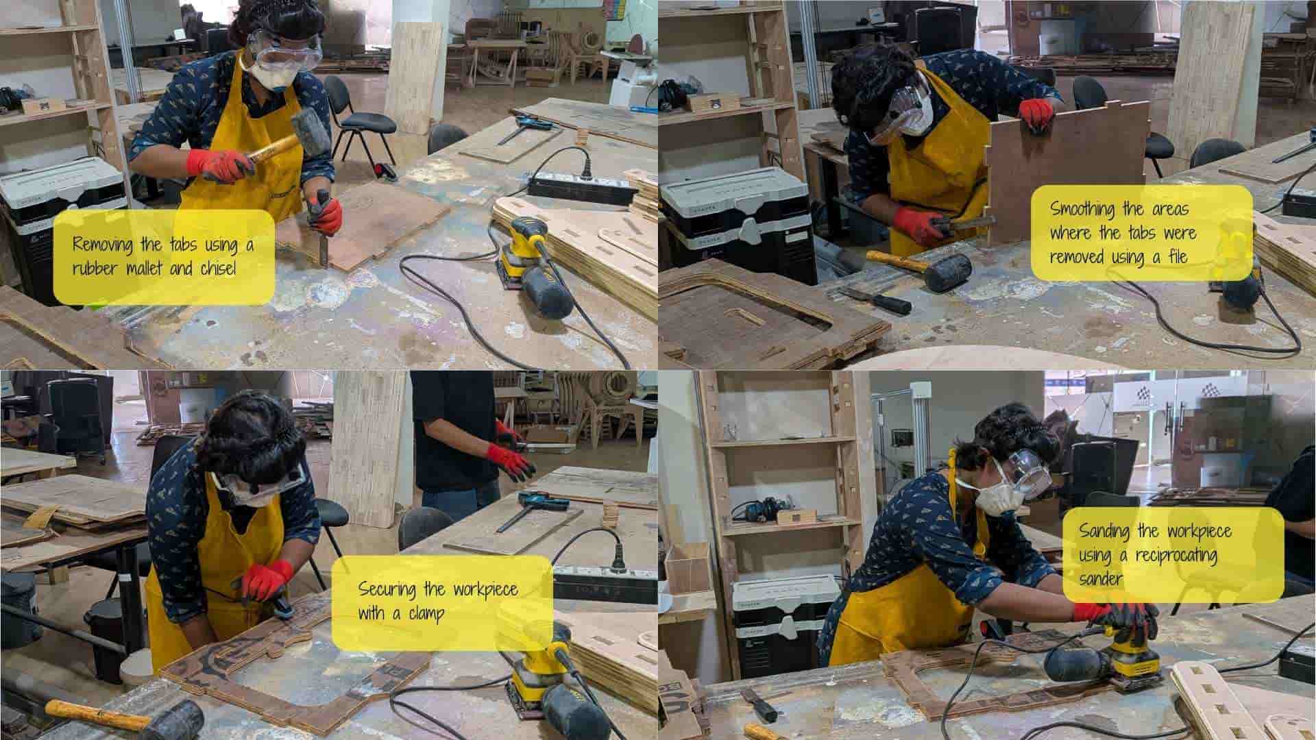
During all post-processing steps, appropriate safety equipment was used. Gloves were worn to protect the hands from splinters, while safety goggles and a face mask were used to protect the eyes and prevent dust from being inhaled. Hair was secured to avoid interference while working with the tools.
After completing the sanding and finishing steps, the components were ready to be assembled to form the final modular storage unit.
Assembly
After completing the post-processing steps, I assembled the first storage module to verify the fit of the press-fit joints and the overall structure. The components fit together well, confirming that the parametric adjustments and CNC machining produced accurate joinery.
Reflection
This week was quite different from the previous weeks. Like every week in the program, it brought a lot of new learnings in design and fabrication, but everything happened at a much larger scale compared to anything we had done before.
The most time-consuming part for me was the design stage. Figuring out the joints took some time. Initially, I planned to use finger joints, but since the unit needed to carry some weight, I was unsure about the stability. Because of that, I redesigned the connections and switched to internal slot-based joinery, which felt more appropriate for the structure.
The laser-cut cardboard test was actually one of the most enjoyable parts. Seeing the miniature version of the storage unit come out of the laser cut assembly was quite satisfying. It looked surprisingly nice and even worked as a tiny storage piece for small items!
Then came the big step: CNC machining. This was the first time we were making something at this scale. Even the preparation itself took time, the CAM and workpiece setup together took nearly an hour. The machining process was definitely the slowest part of the week, and everything around it also required patience. Post-processing was a dusty experience and left me with a few body aches (clearly a reminder that I haven’t been working out regularly!)
The assembly stage was the most satisfying part of the entire process. Seeing all the pieces fit together so well without major issues was extremely rewarding. It felt great to see a design go from a digital model to a full-scale physical object.
Overall, I am really glad to have learned this workflow. The process has already sparked many more ideas in my head for future projects. Like the previous weeks, this week also taught me several valuable lessons, both technical and practical.