Week 3: Computer-Controlled Cutting
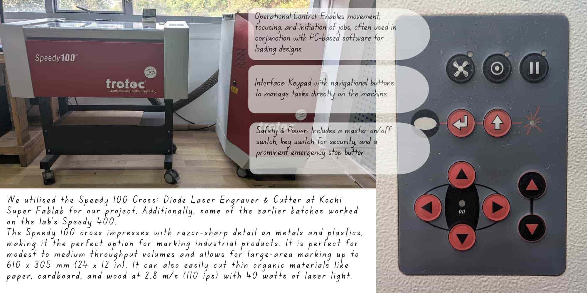
This week focused on digital fabrication through 2D cutting, using vinyl cutting and laser cutting to transform parametric designs into physical objects. We explored how CAD and CAM workflows translate into machine operations, and how parameters such as power, speed, focus, kerf, and joint clearance directly influence the final outcome. Through hands-on work, I created vinyl stickers, designed a parametric laser-cut construction kit, and participated in the group characterization of our lab’s laser cutter. A lot of amazing things were taught by our instructors, Saheen and Akash, and they were directly applied to achieve tangible outcomes.
Group Assignment
The Group Assignment can be found on this link.
The week began with understanding lab safety protocols and the workflow, specifications, and operating parameters of the laser cutter and vinyl cutter. We focused on machine characterization by studying focus, power, speed, rate, kerf, and joint clearance.
Safety Training
Strict safety measures were followed during operation:
A detailed documented version can be found on the Group Assignment page .
Process
Through hands-on testing, I developed a clearer understanding of how parameters such as power, speed, and focus affect cutting and engraving performance. A key concept explored was kerf, the material width removed by the laser, which directly impacts press-fit assemblies. Before cutting, design files were color-coded using standard conventions to distinguish between cutting and engraving operations.
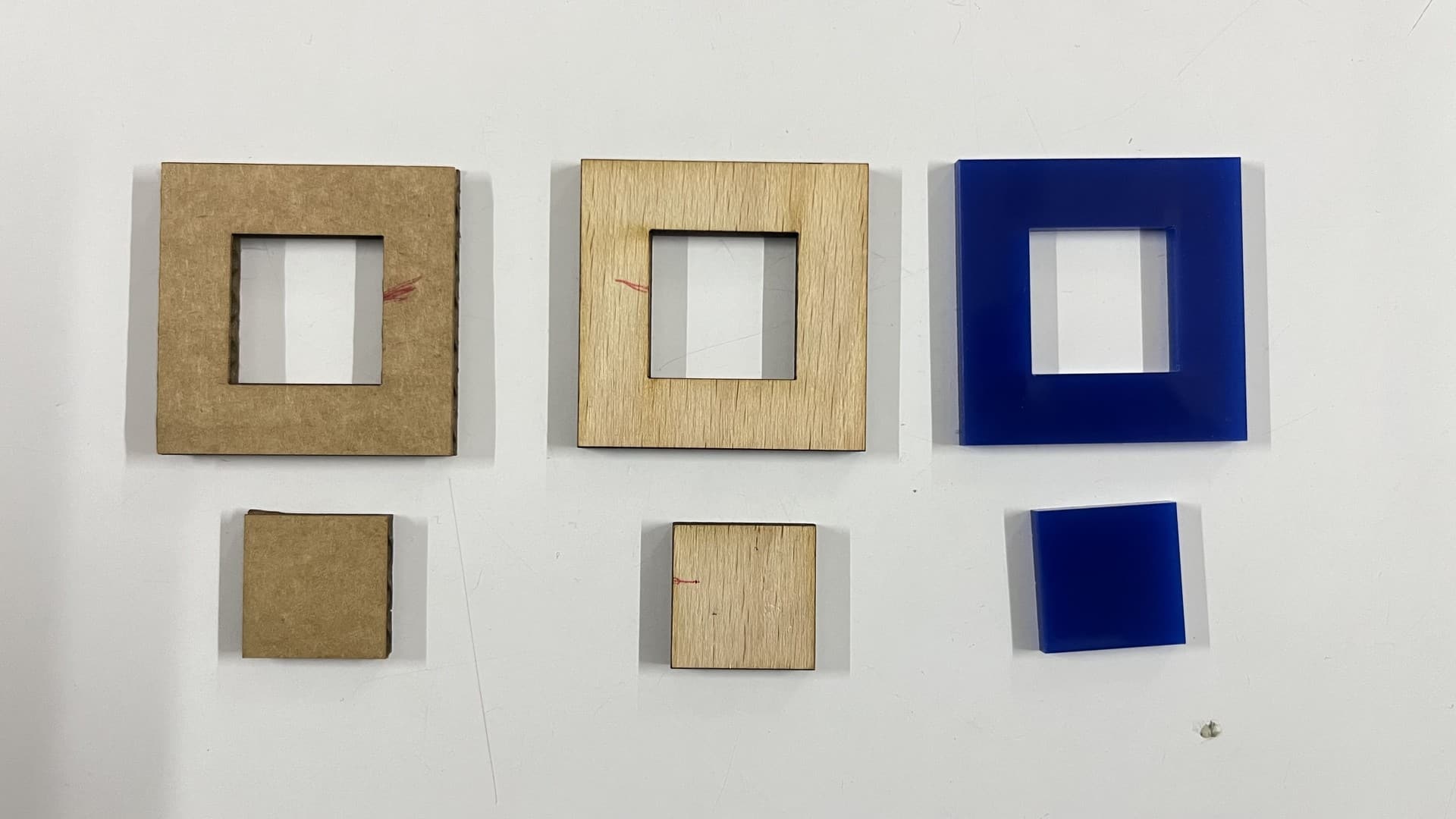
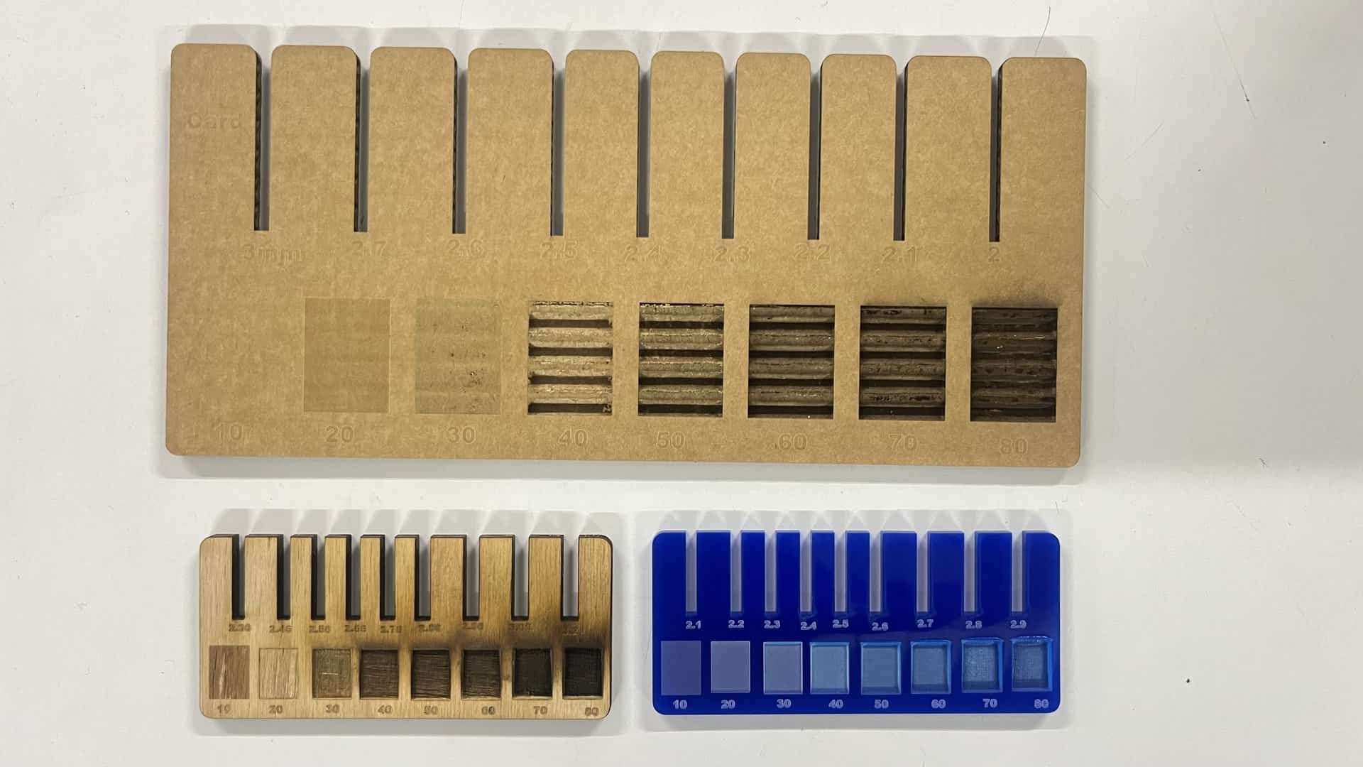
To obtain the kerf value, we laser-cut a 40 × 40 mm square with a 20 × 20 mm inner cutout from cardboard. After cutting, we measured the inner dimension of the larger square and the outer dimension of the smaller square. The difference between these two measured values gave the total kerf, which was then divided by two to calculate the kerf for the material. We also experimented with engraving settings, observing that lower power produced lighter surface marks, while higher power and slower speeds resulted in deeper engravings. This helped in understanding how to balance power and speed to achieve desired engraving effects on different materials. These tests were then repeated on birch wood and acrylic sheet as well. The detailed documentation can be viewed on the group's page.
The final values we figured for the parametric press-fit pieces for Cardboard are:
The effective kerf was found to be approximately:
Individual Assignment: Vinyl Cutting
Reference: GX-24 User's Manual
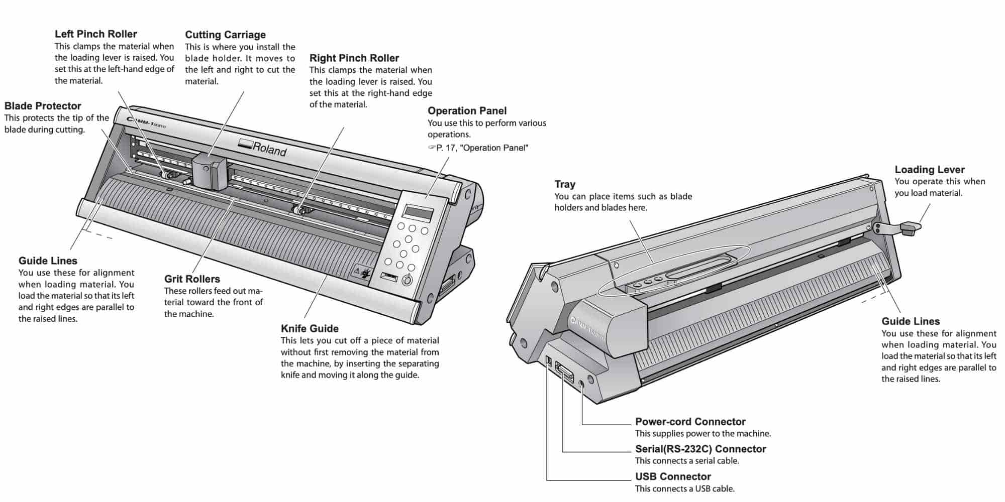
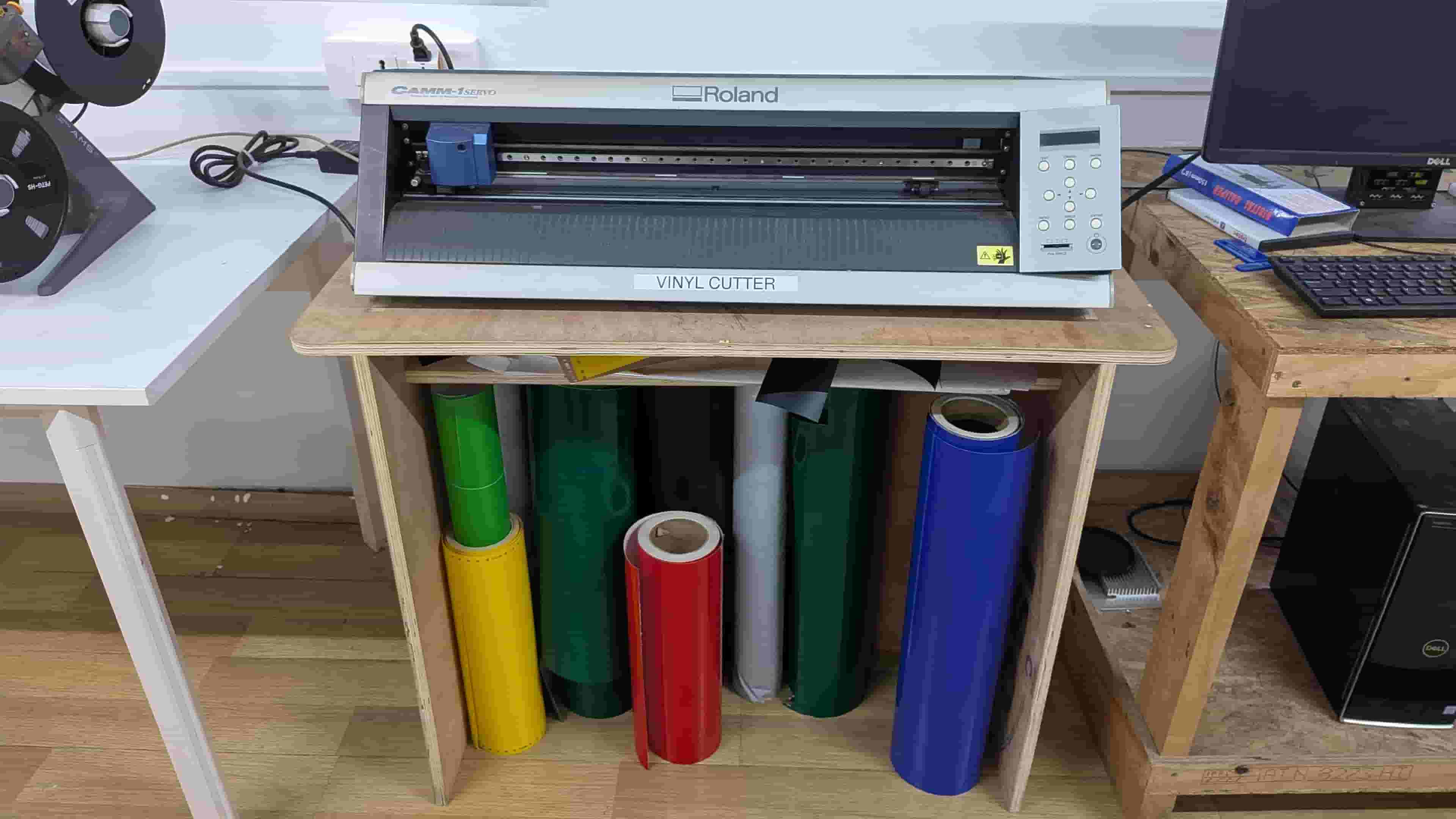
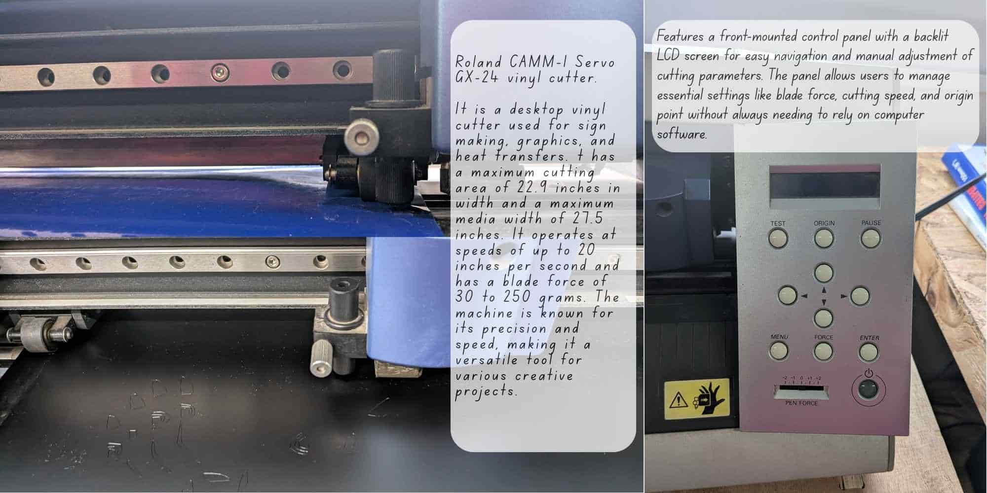
Vinyl cutting is a fabrication process used to cut patterns and shapes into vinyl sheets for producing stickers and decals of various sizes. The machine used is a Roland GX-24 / GS-24, equipped with an adjustable blade holder that allows control over cutting depth and blade replacement. Cutting is achieved through the coordinated motion of the blade along the X-axis and the movement of the vinyl sheet along the Y-axis, enabling precise cutting in the XY plane.
Designing and Cutting a Vinyl Sticker
The next part of the assignment was making stickers using vinyl sheets. We used the Roland GX-24 / GS-24 Vinyl Cutter, a precision machine designed for cutting thin materials like adhesive vinyl, heat transfer vinyl, and stencils.
The vinyl roll is placed on the rollers behind the machine and locked in place using the lever, making sure the sensor is covered by the vinyl sheet. From the control panel, we set the feed type (roll, sheet, or piece), and adjust the origin, force, and speed.
After switching on the machine, we select roll and press enter, allowing the cutter to measure the vinyl sheet. The blade is positioned and the origin is set before cutting. Force, speed, and blade depth are finalized using a test cut. A correct test cut is when the outer circle peels off, while the inner square remains intact.
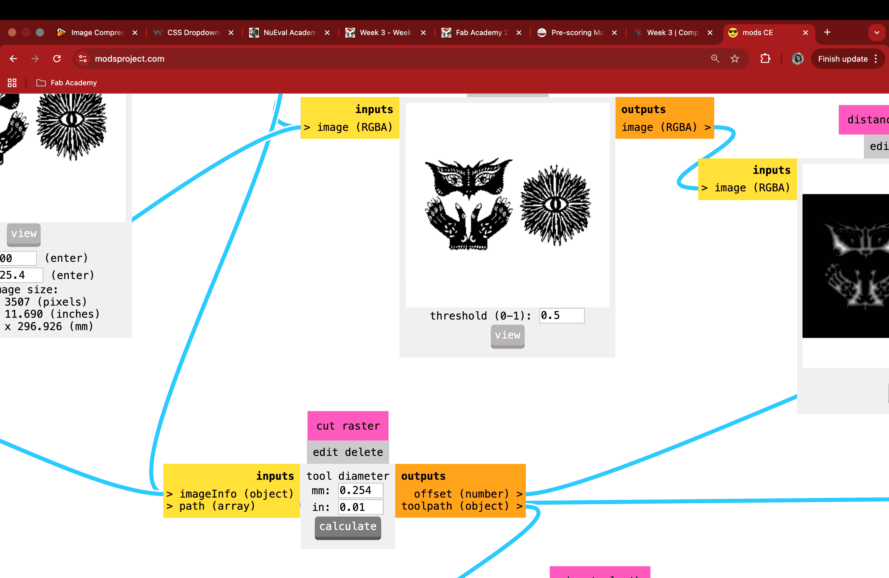
To control the machine, we used ModsCE(Community Edition), an open-source, cross-platform tool developed at MIT and used in our fablab for both vinyl cutting and PCB milling. In ModsCE, we import the SVG file, adjust the speed(force is set directly on the machine), then press calculate followed by send the saved file to start the operation. These steps are repeated every time a parameter is changed.
The Story Behind My Sticker
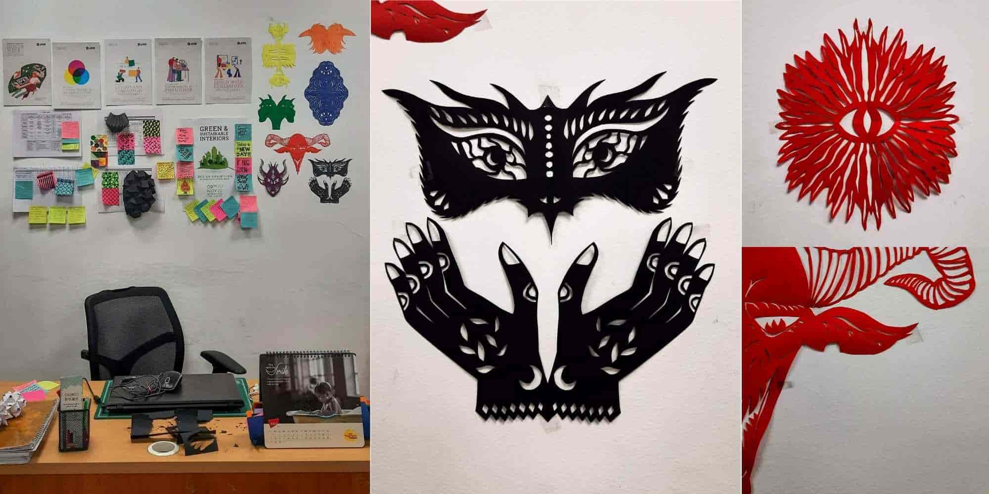
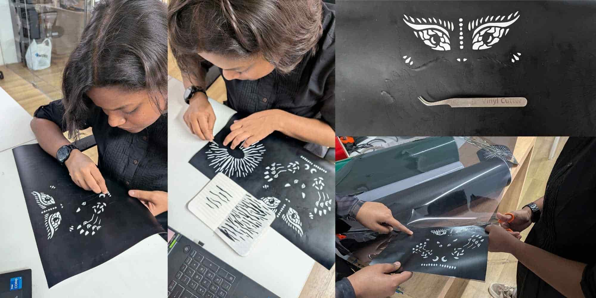
I am fond of creating hand-cut paper illustrations, and I had created a bunch of them a few years ago and put them up on my staffroom wall behind my desk. When this assignment was announced, I immediately thought of recreating some of those stencils on vinyl to create stickers. You can find the image of my staffroom wall below, along with the original hand-cut paper stencil images.
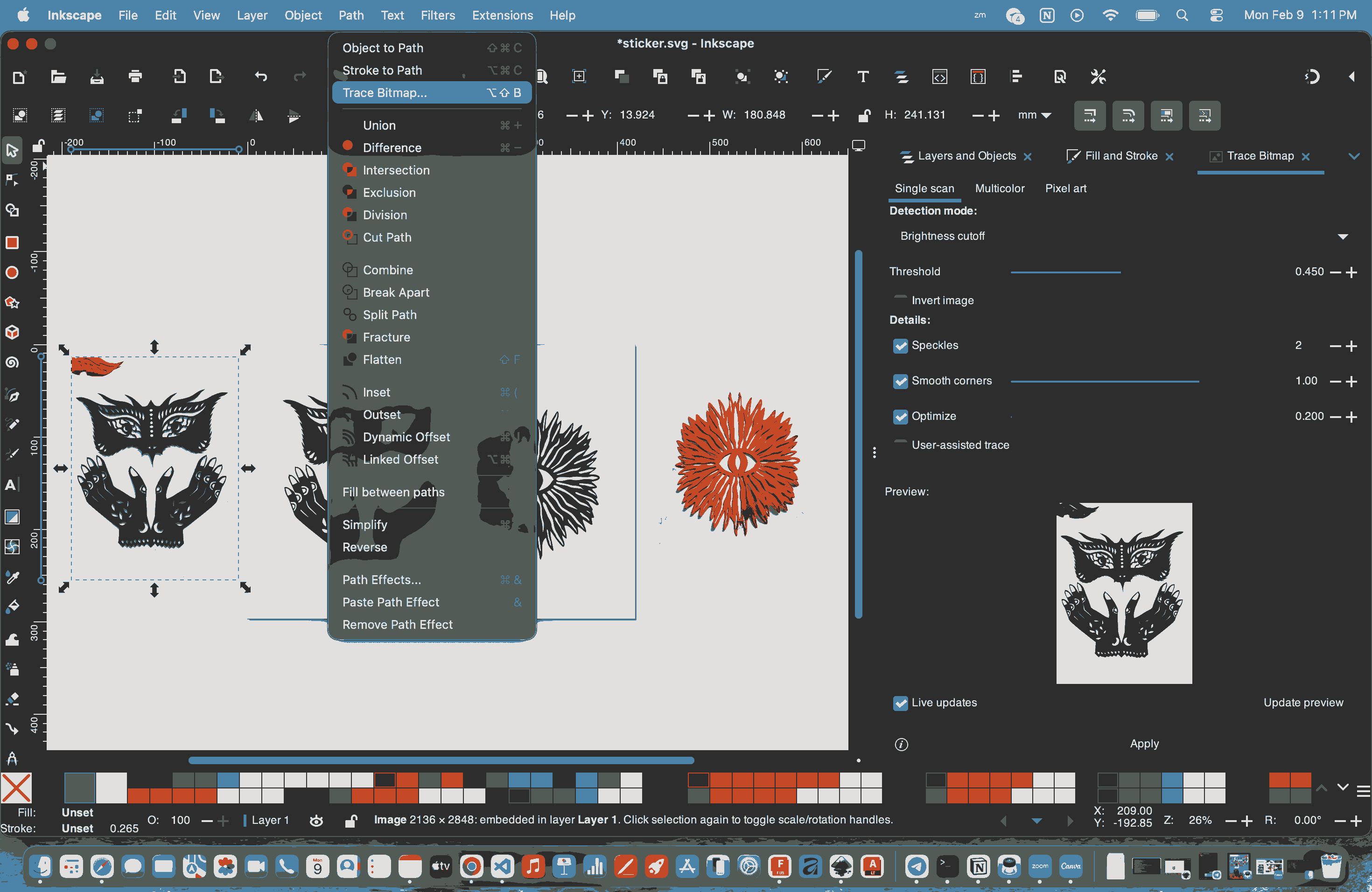
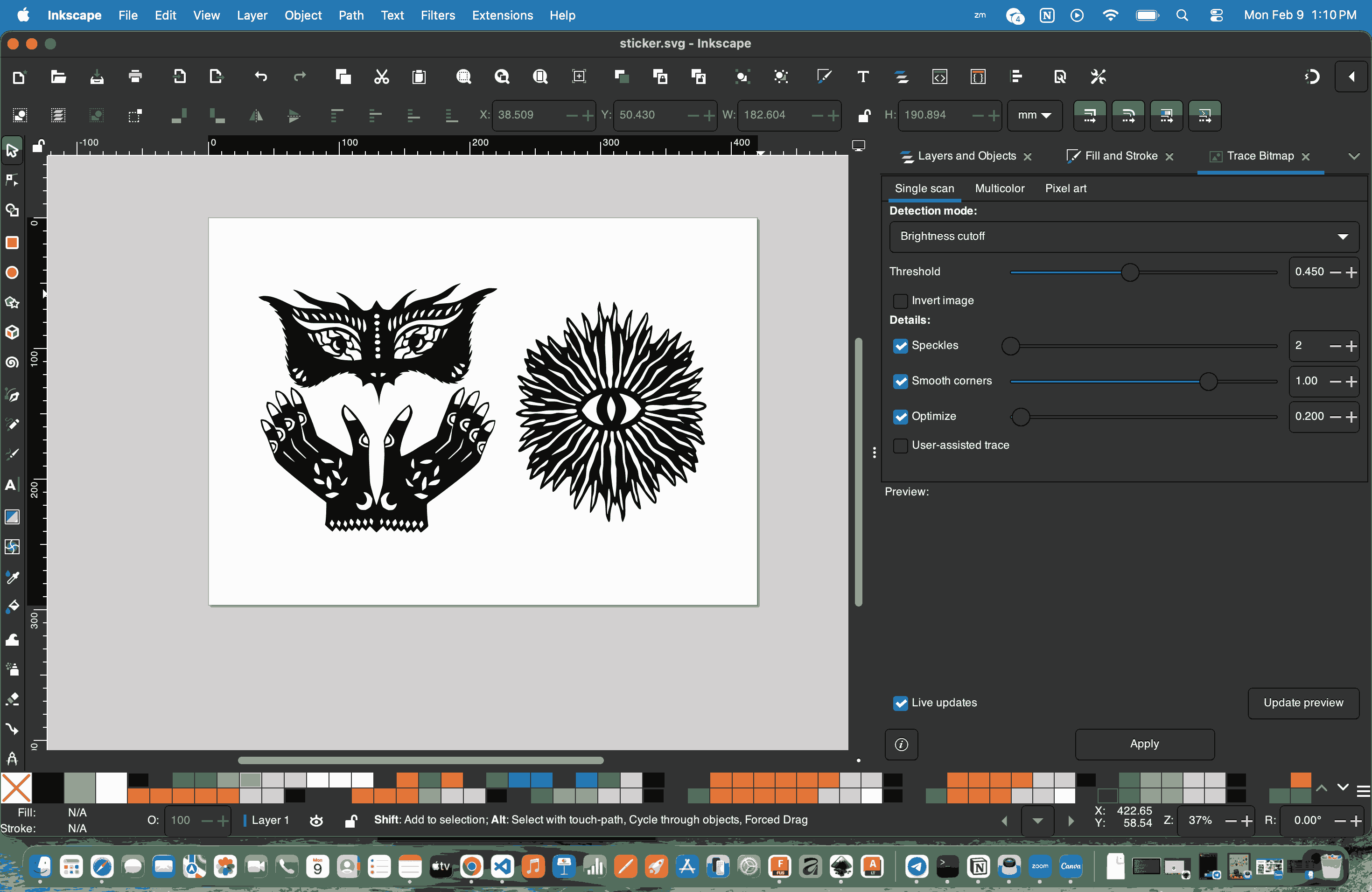
To do the assignment, I first imported the original image into Inkscape and used bitmap tracing to obtain an SVG file. I made sure the stroke was kept blank and the fill was turned on. These steps were repeated for the other images as well.
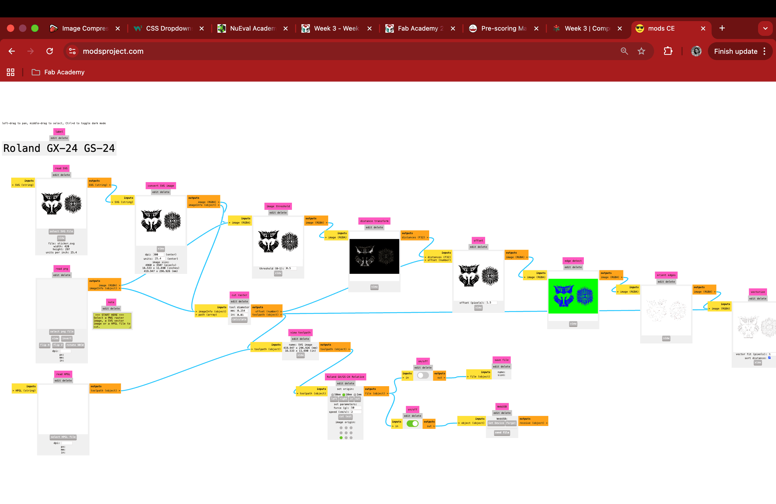
Once I had satisfactory SVG files, I opened them in Mods, calculated and previewed the toolpath, ensured there was enough clearance space within the border, and then sent the file to the vinyl cutter.
Workflow in ModsCE for the Roland GX-24 Vinyl Cutter
To follow the Software Workflow (Mods), connect the machine with the computer, I used modsproject.org.
In ModsCE, the workflow begins at Selection by right-clicking the canvas to navigate through
Programs → Open Program → Roland → Vinyl Cutter → GX-24,
which loads the appropriate cutting environment for the machine.
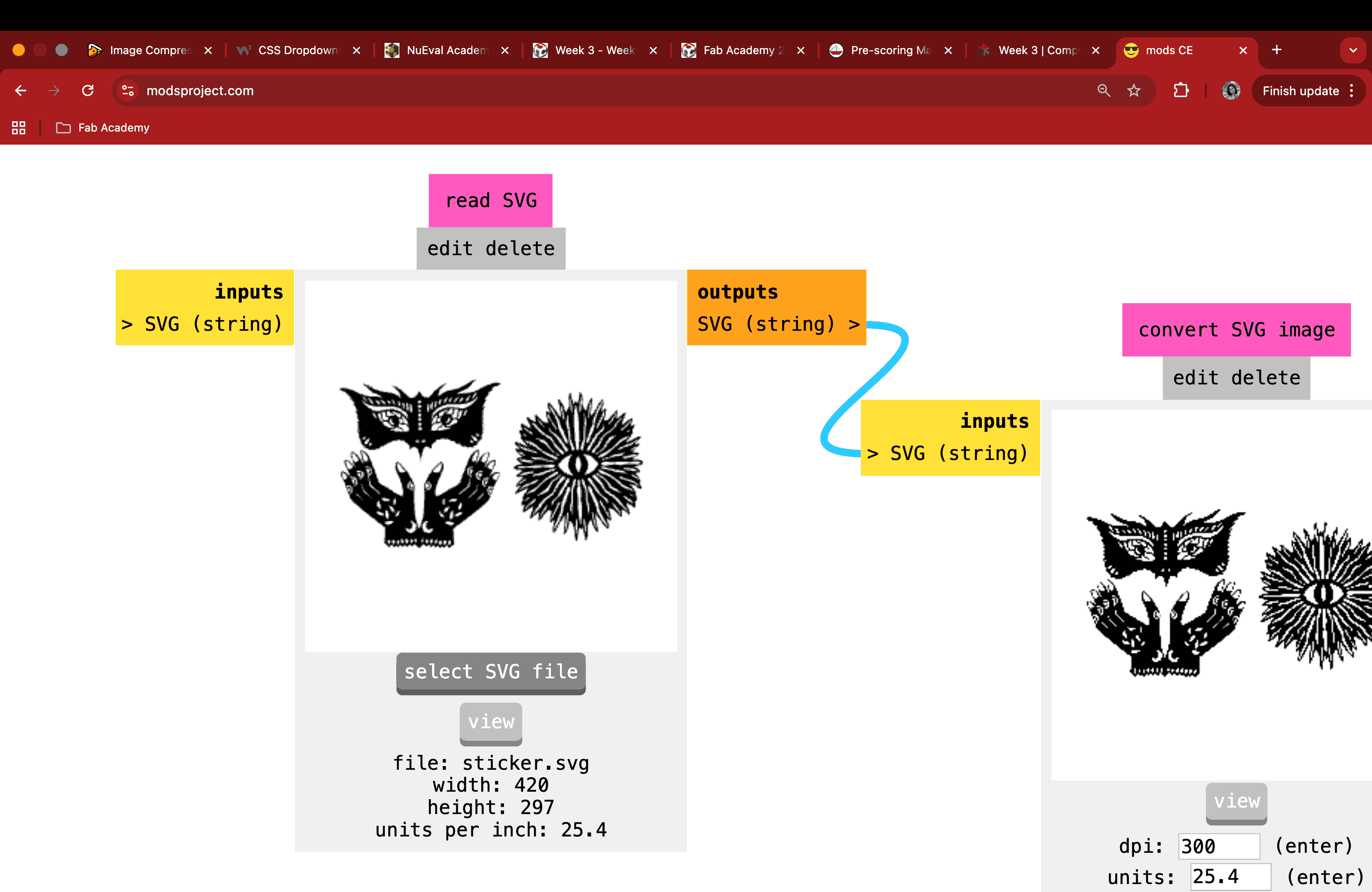
Once the program is loaded, the SVG file is imported during the Conversion stage, where the offset is set to 1 to ensure the cut paths are correctly interpreted and scaled for the cutter.
With the file prepared, we move to Origin, where the tool head is manually positioned to the desired start point on the vinyl sheet, and the Origin button on the GX-24 is long-pressed to register that position as the reference point for the cut.
Finally, at the Send stage, the file is transmitted to the cutter using the WebSocket serial node, which communicates directly with the GX-24 to initiate the cutting operation.
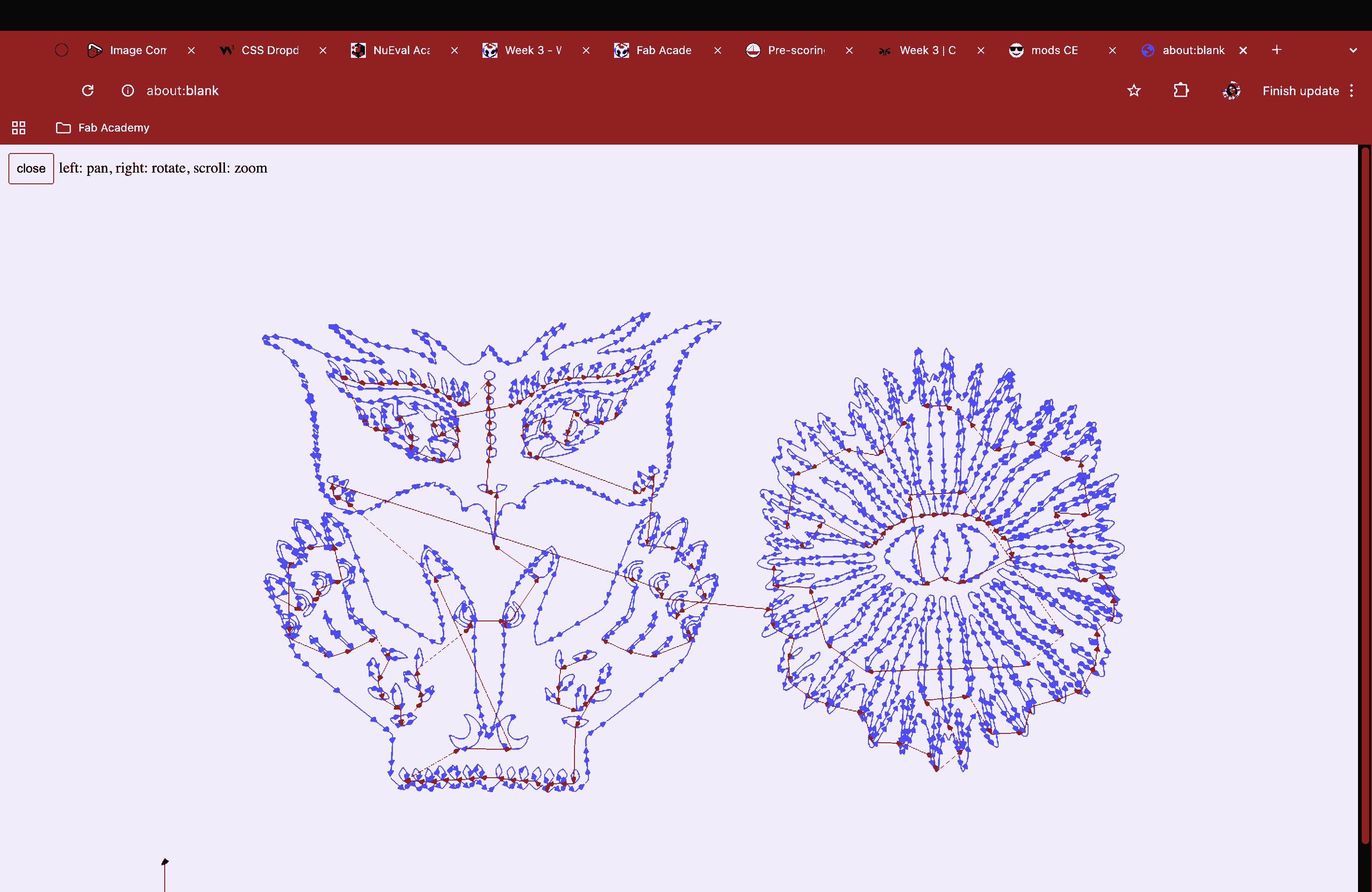
The cutting process took a few minutes, as my stencil had a lot of intricate details, but I was excited to see it come together.
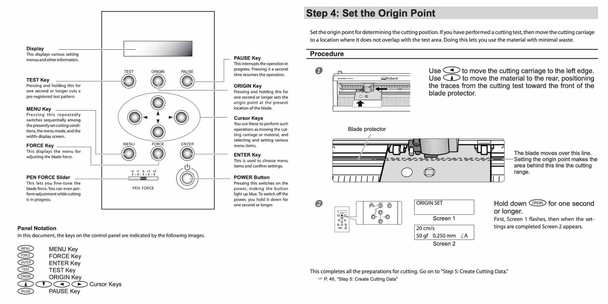
Reference: GX-24 User's Manual
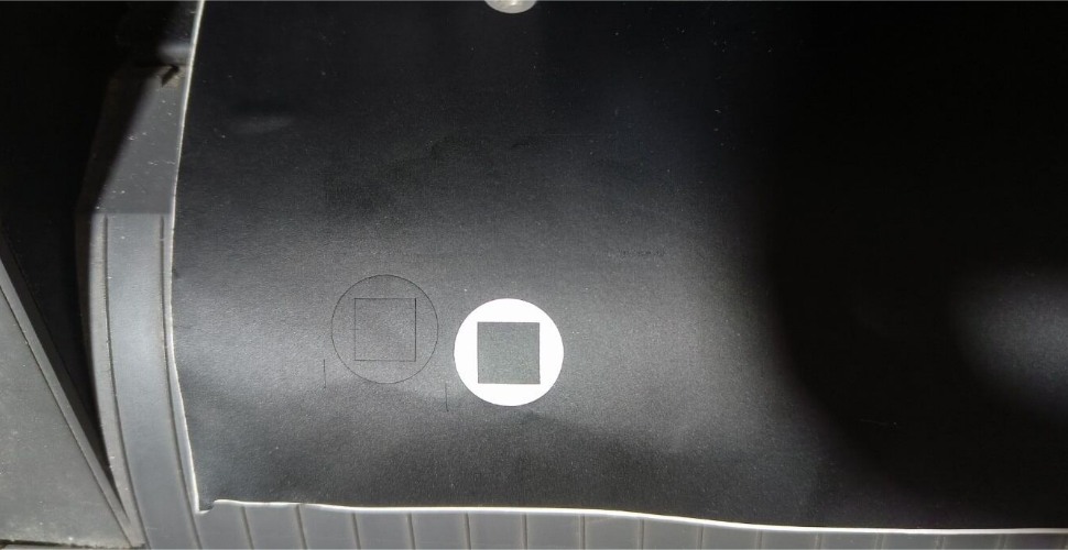
Image: Test cut by setting the speed to 2 cm/s and the force to 100 gf (Image credits: Ali Abdul Gafoor)
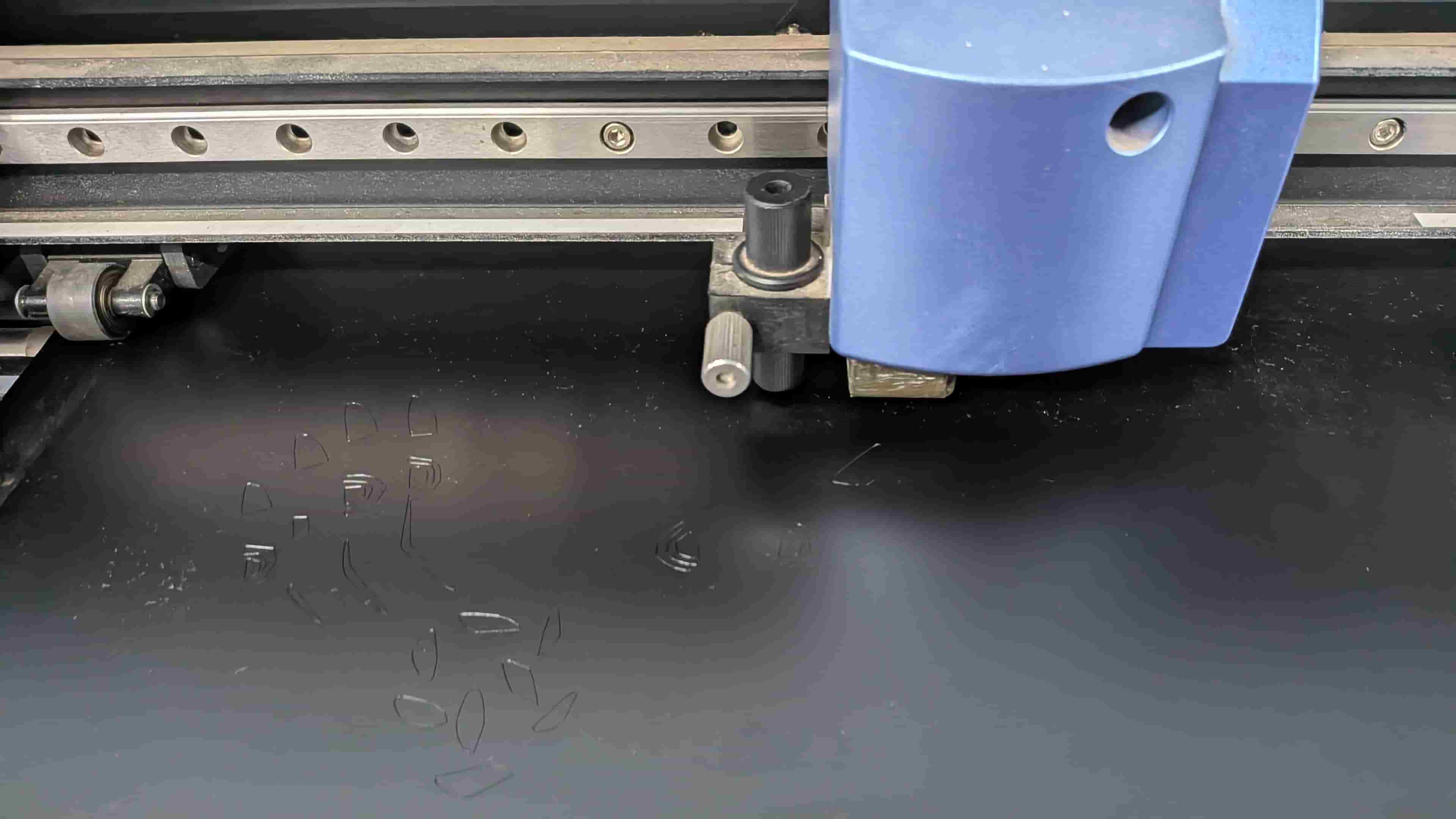
Image: Cutting the sticker file
Weeding and Transfer
Once the cutting was done, I removed the cut portion from the roll and then sat down with a tweezer to peel off the unwanted areas. This process felt surprisingly meditative.
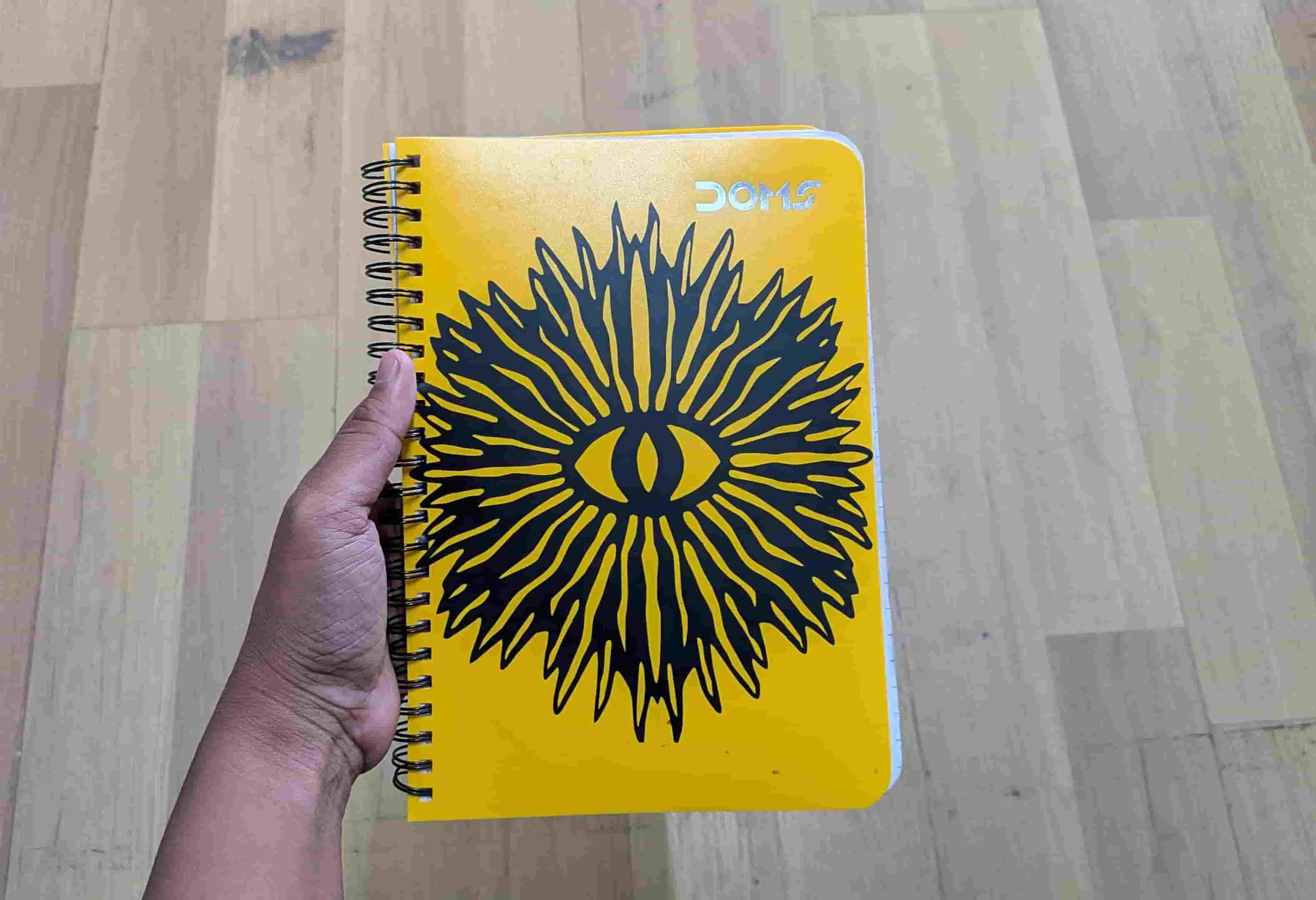
Later, I used a cooling film as transfer sheet to lift the required part of the sticker from the vinyl sheet and pasted it onto the notebook cover of my classmate, Ashtami. She wanted the sticker on her cover.
I then used my metro card to thoroughly scrape over the transfer sheet to ensure the sticker adhered properly to the cover. A tweezer was again helpful for handling the finer details.
I still have the other stickers with me, unfortunately I haven't found a place to stick those yet.
Hero Shot
Reflection - Vinyl Cutting Experience
Like I mentioned before, I do have experience with hand-cut paper illustrations. But the thing with doing it manually is that it takes a lot of time, tests your patience, questions your choices, and sometimes even your existence, just kidding. With the vinyl cutter, everything became ten times easier. It would normally take me a good 30 minutes to finish one paper-cut illustration, but this time it hardly took me 10 minutes to peel off the excess vinyl and transfer the final sticker. I guess this is where technology really comes into play, to make our lives better, faster, and easier without compromising our skill. I would actually encourage everyone to design intricate patterns because the vinyl cutter will handle the cutting for you. So why compromise on the pattern? The entire process was not just satisfying, but also a lot of fun. I would do this a hundred times again!
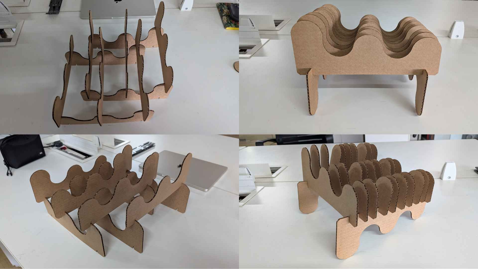
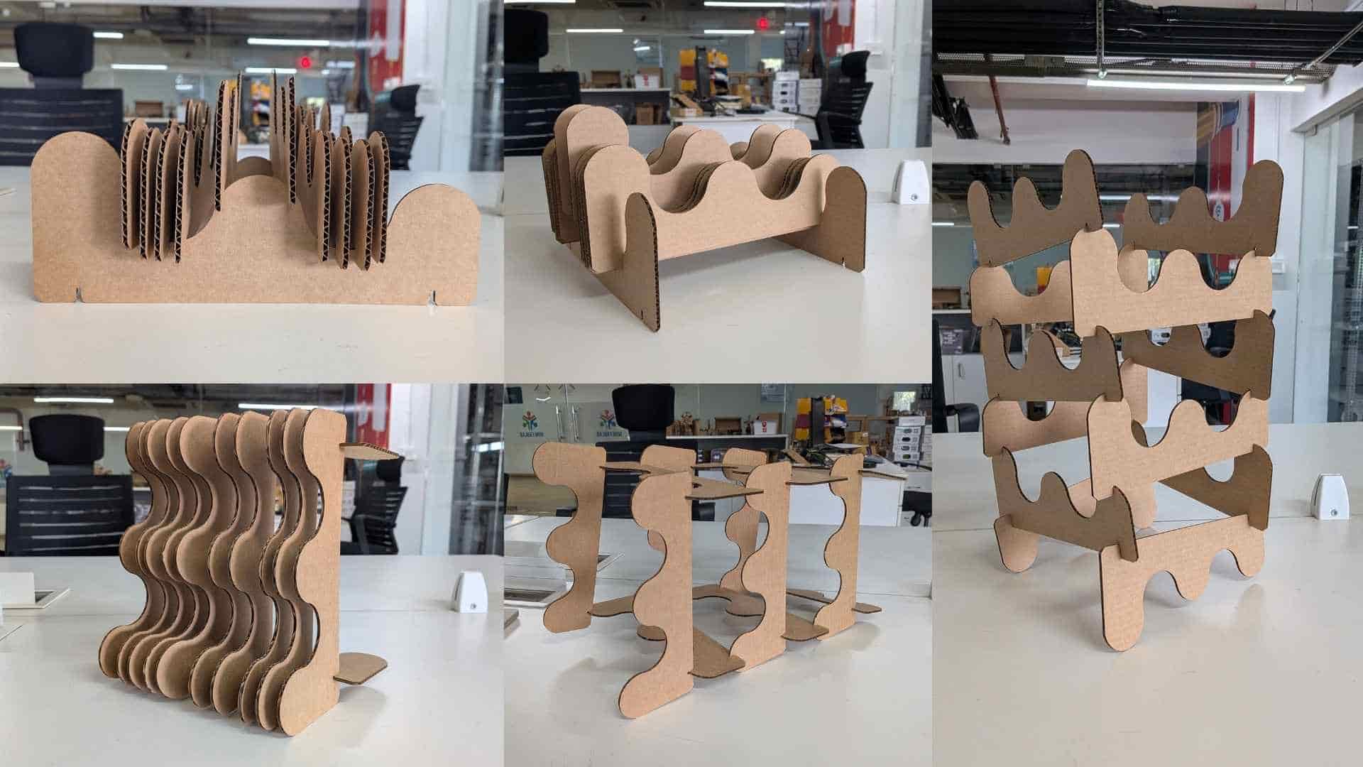
Designing a Parametric Press-fit Construction Kit
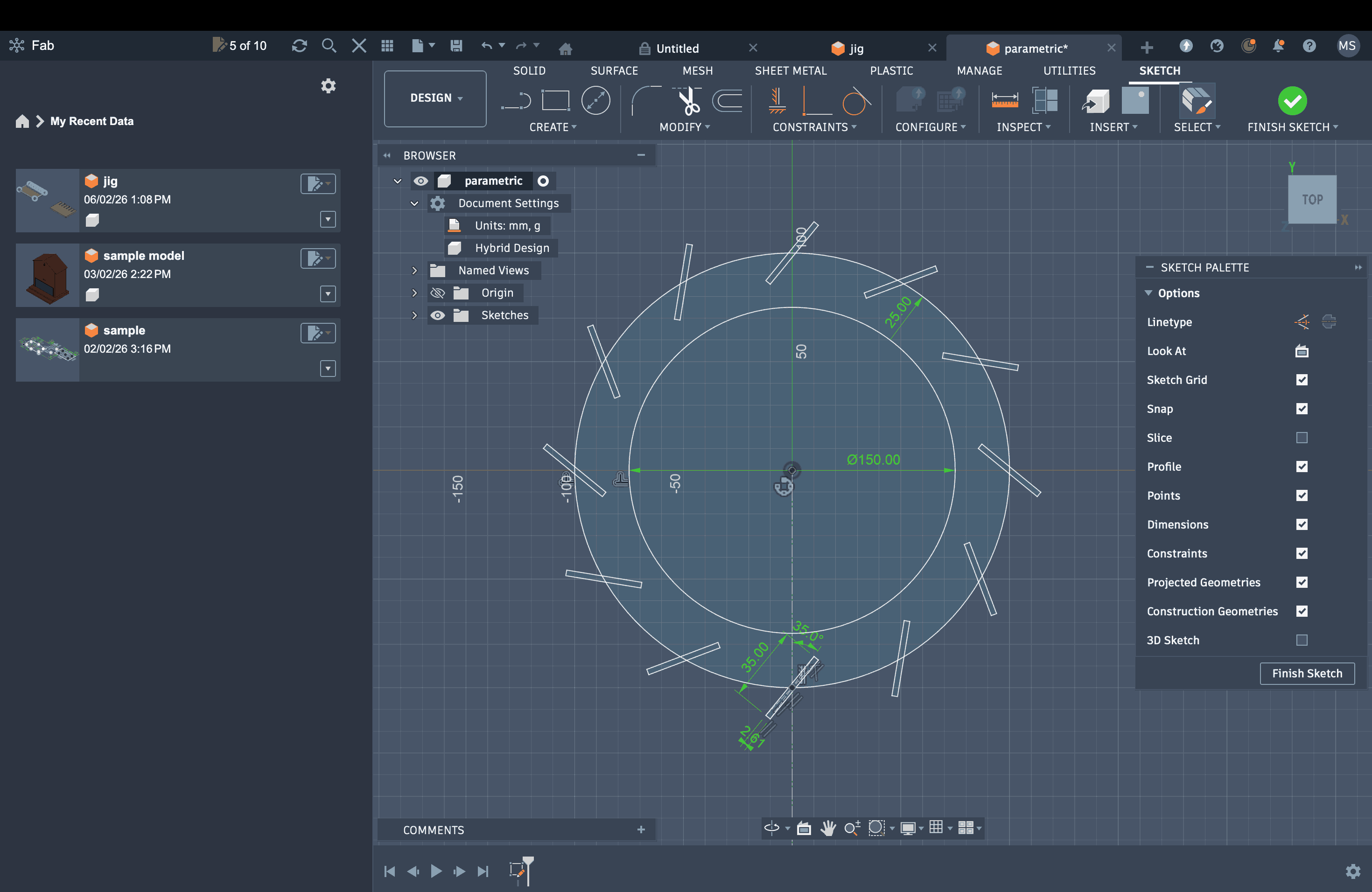
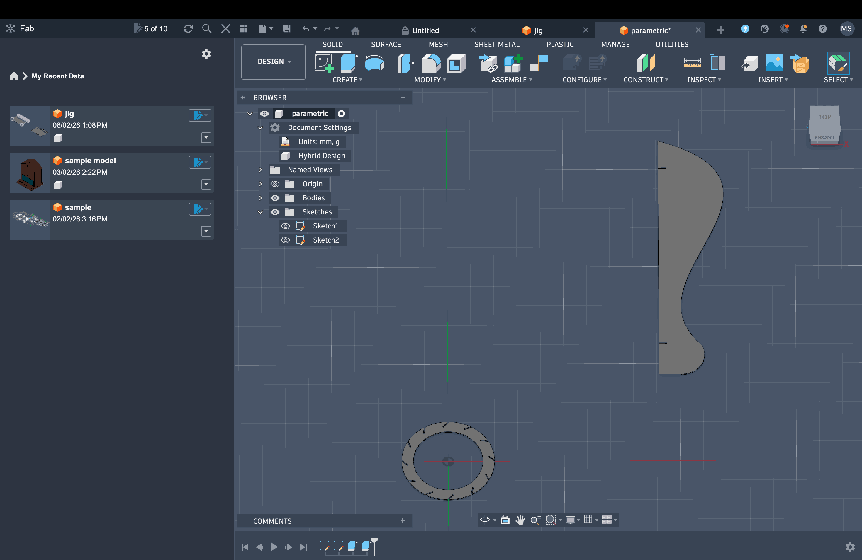
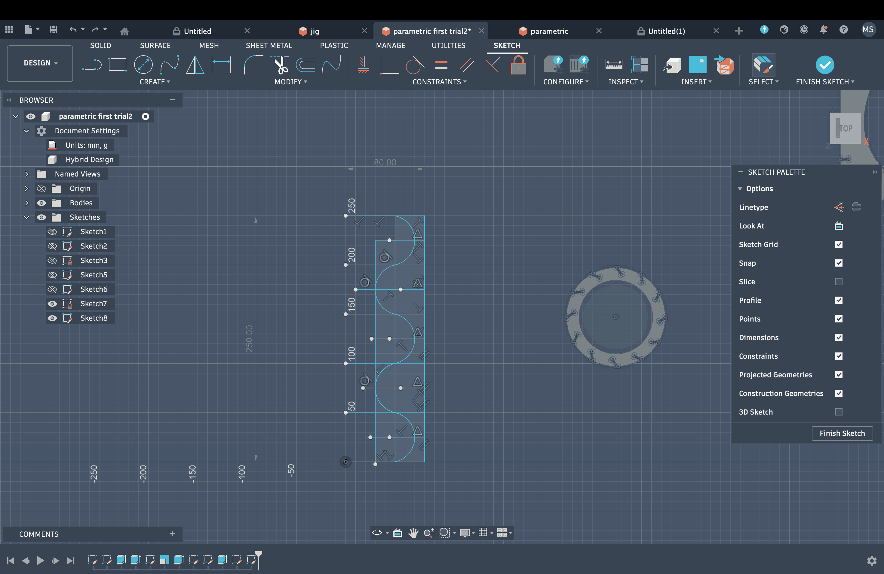
I started by sketching the basic component on Fusion 360, which in my case was a circle, and then created an offset.
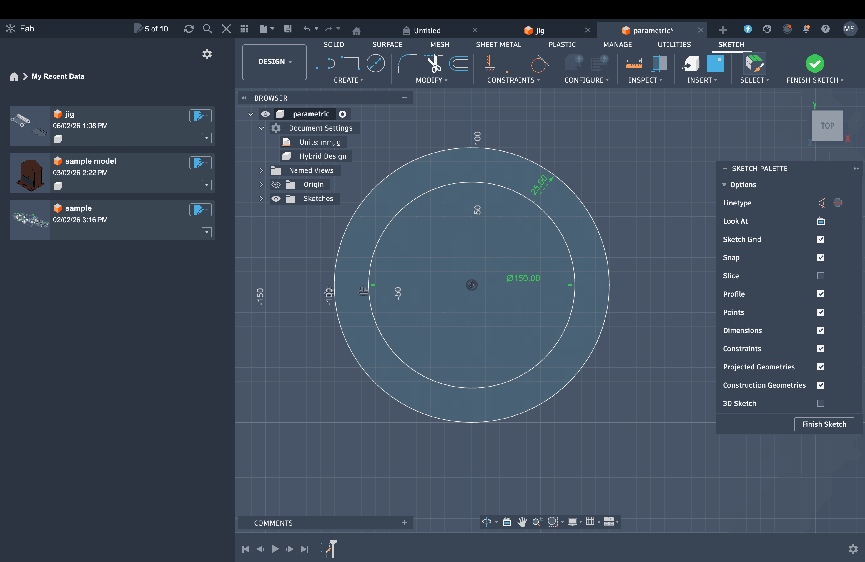
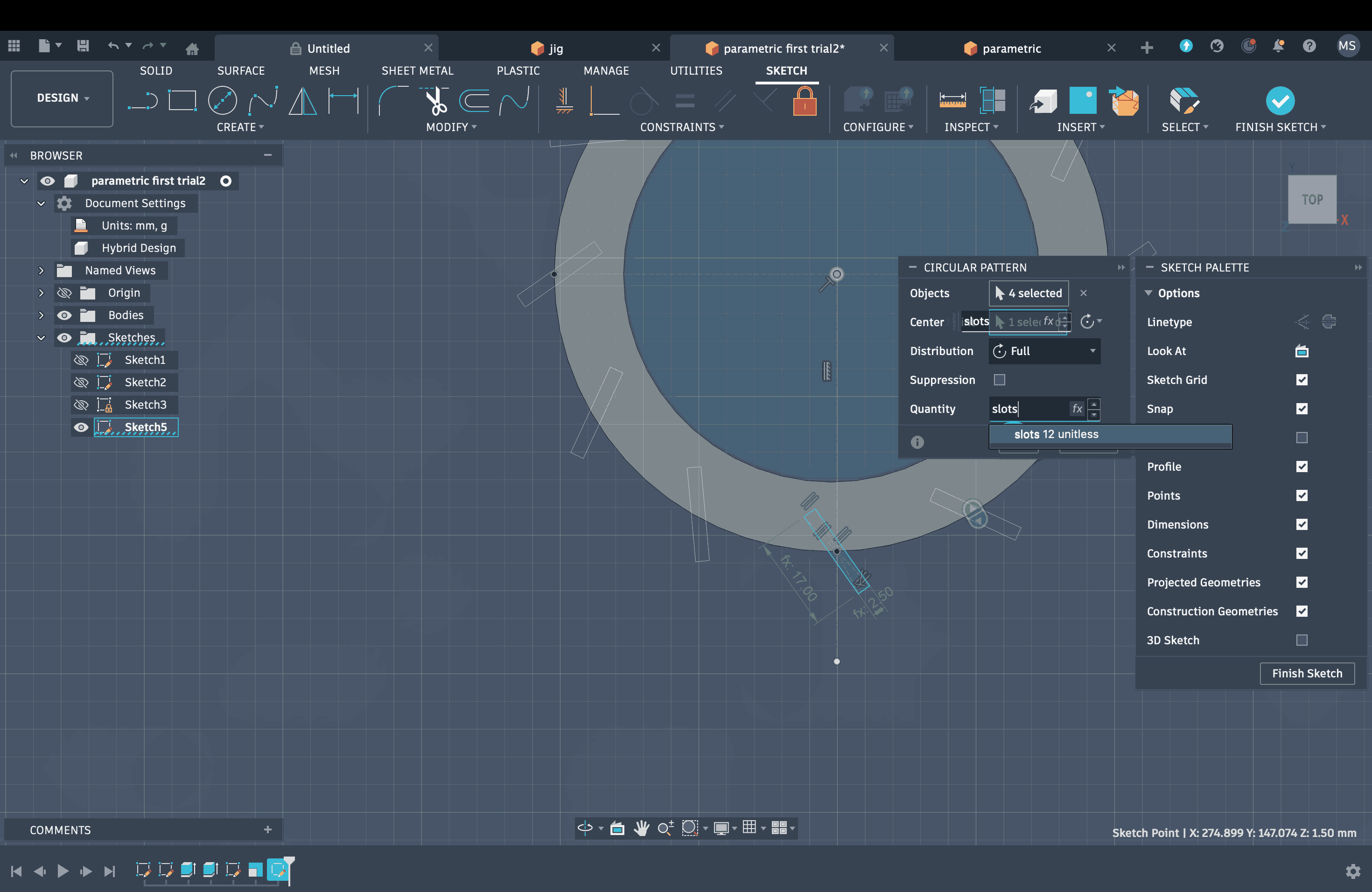
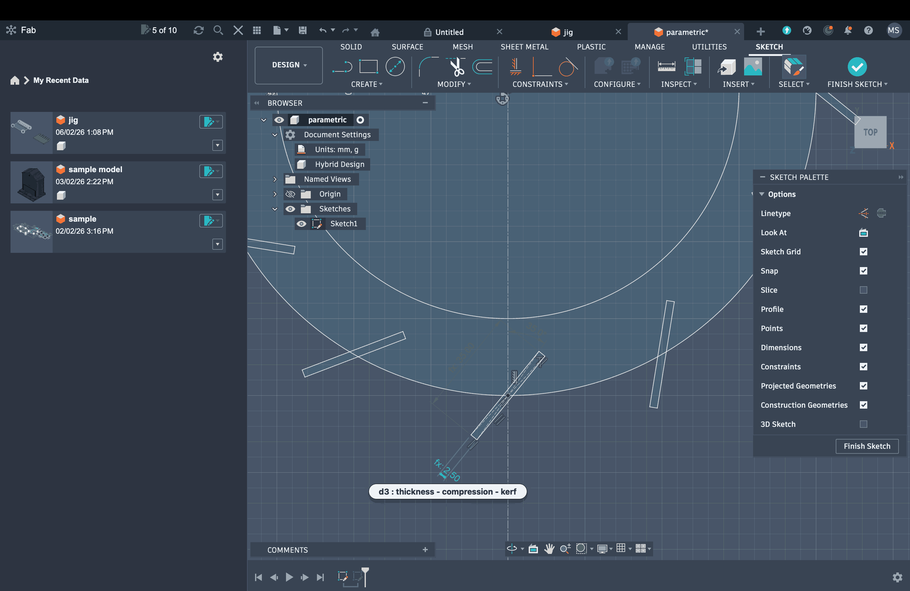
I am planning to make a press-fit lamp. Before drawing the slots, I added a few parameters: slot length set to 17 mm, material thickness to 3 mm, kerf to 0.3 mm, and compression to 0.2 mm.
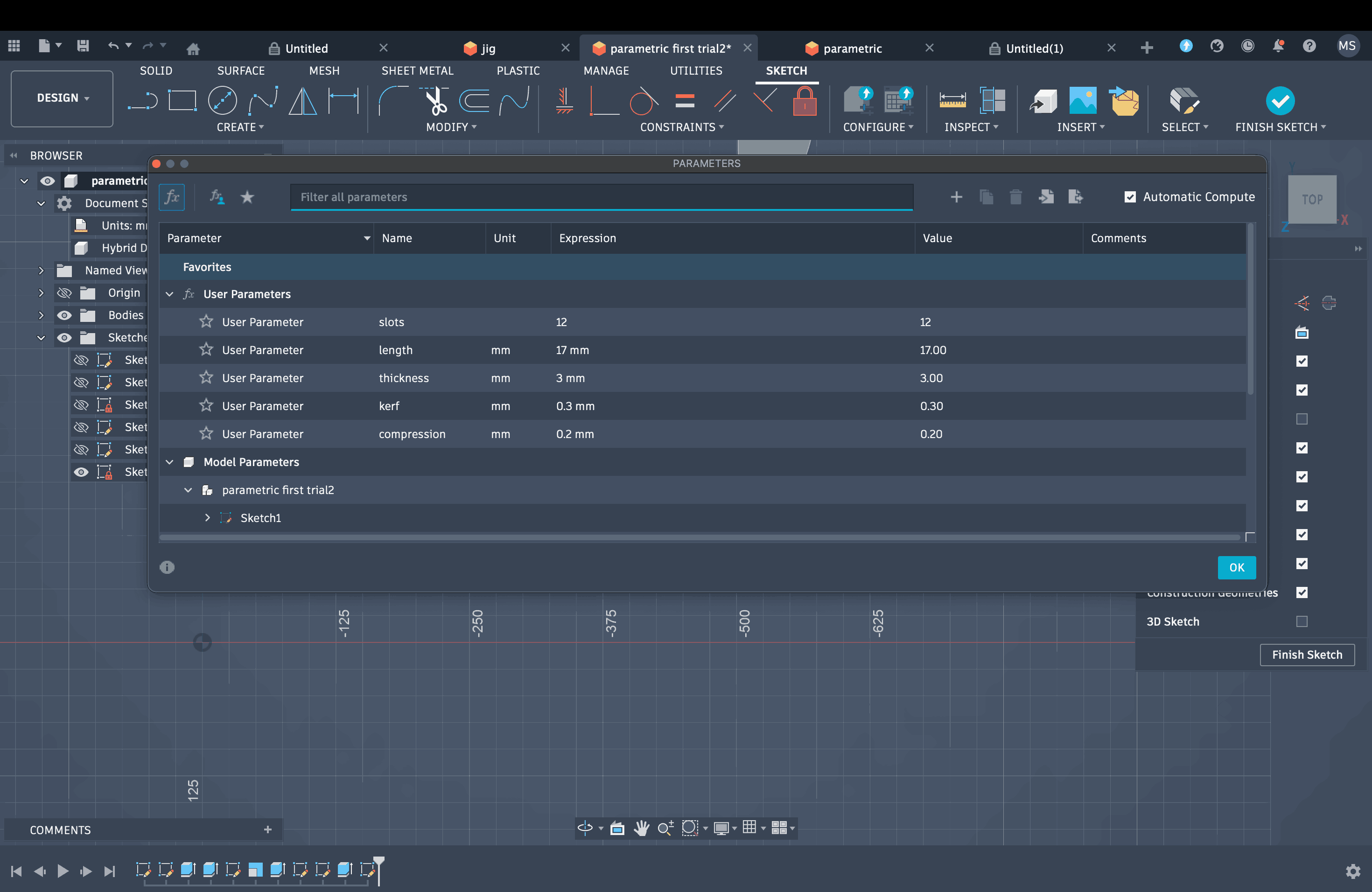
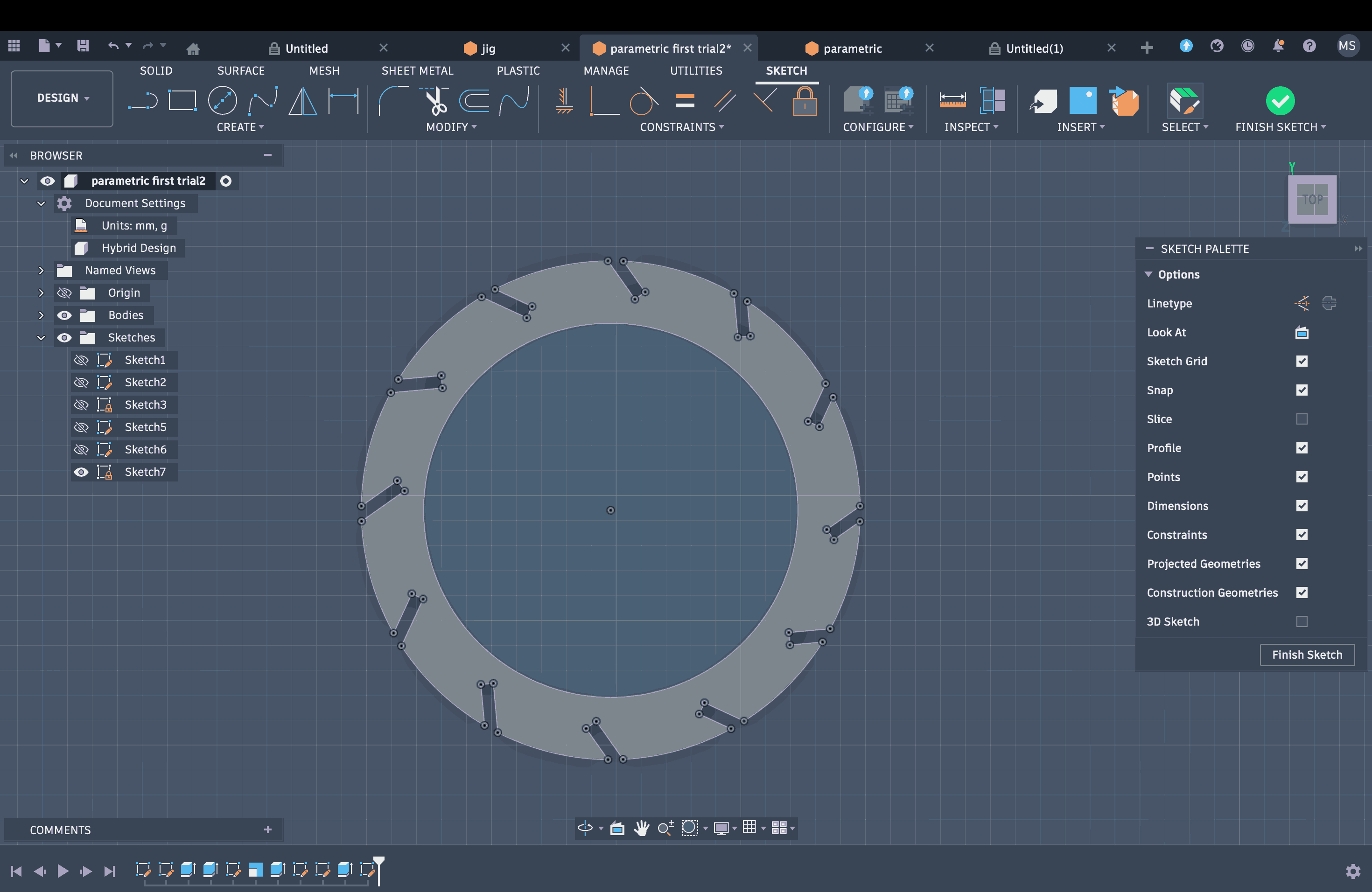
After that, I added another constraint for the number of slots, which was set to 12. I then drew a single slot, applied the parameters, and used the circular pattern tool along with the slot number parameter to create the remaining slots around the original circle.
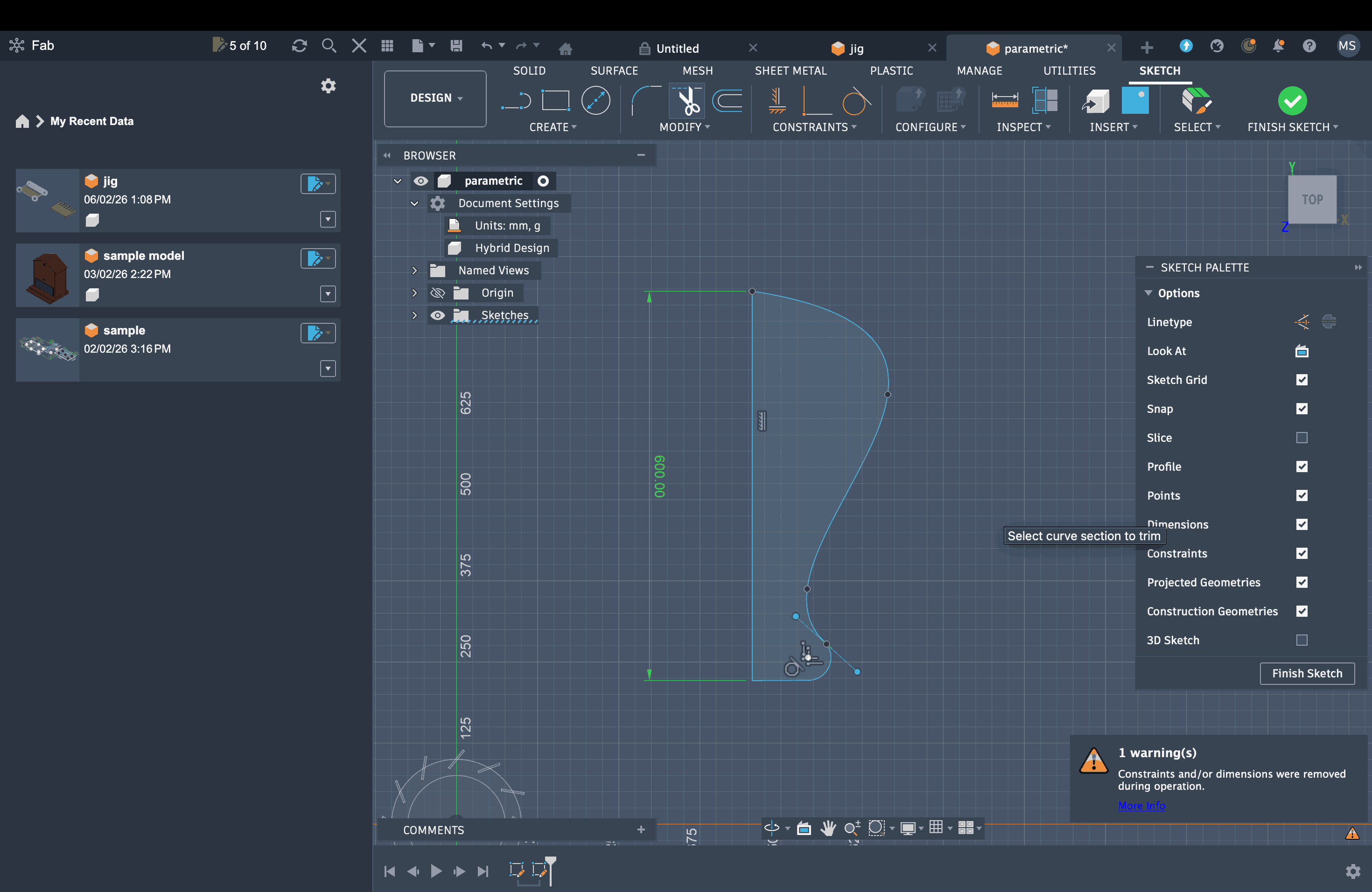
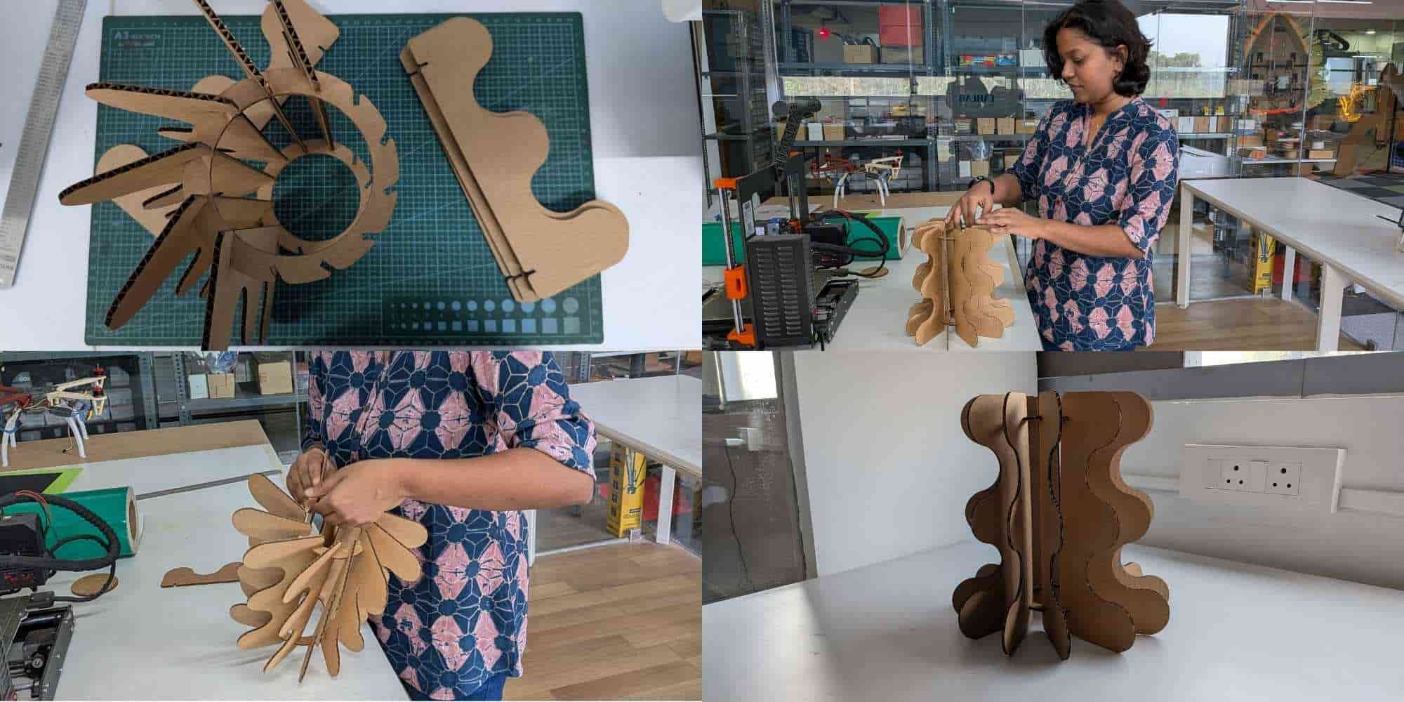
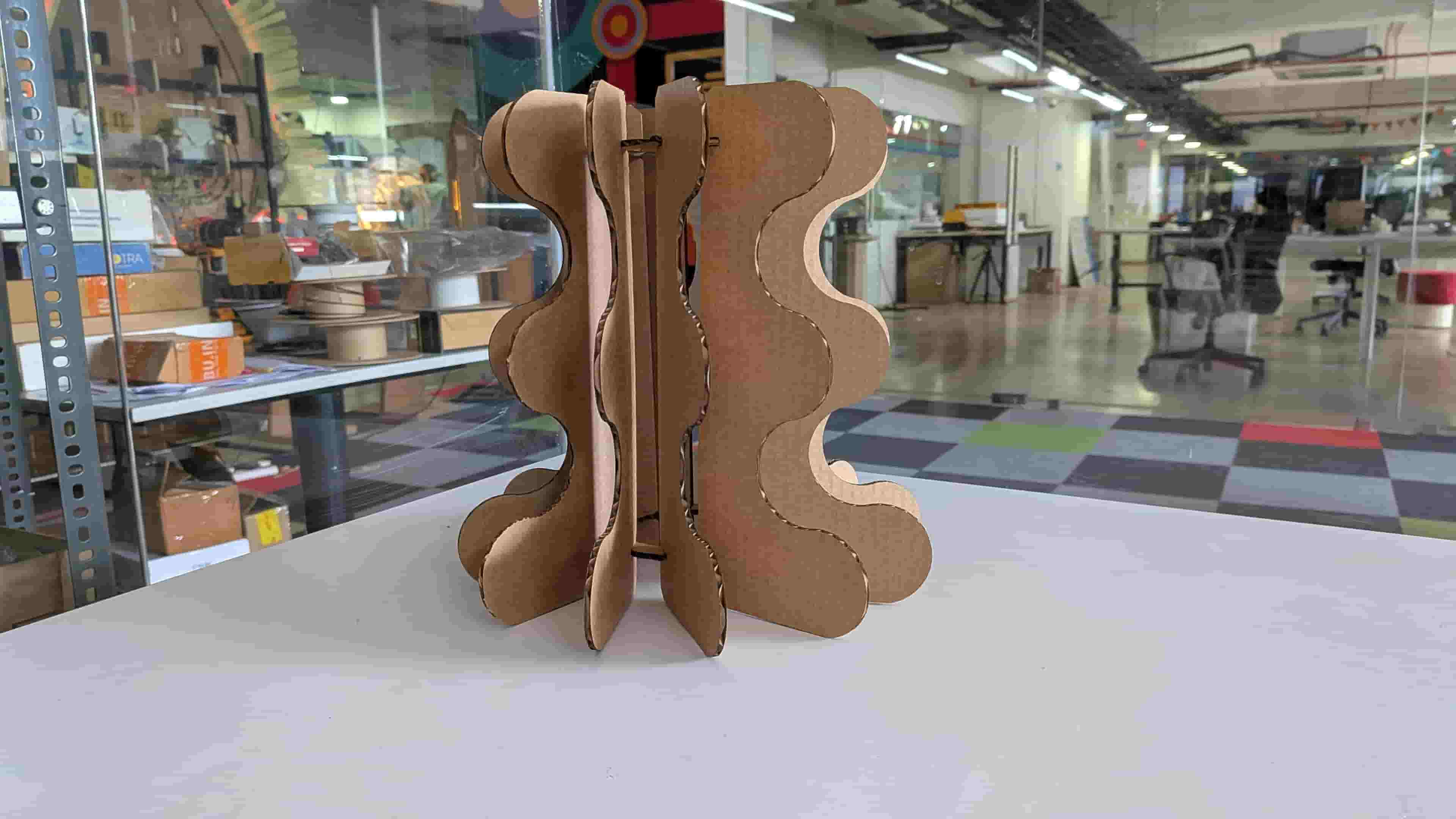
Once that sketch was complete, I moved on to creating my second sketch, which is the vertical component of the lamp. Since this part required a curvilinear form, I used the spline tool to create the curves on one side, and a straight edge with two slots on the inner side.
As a sample needs to be tested before finalizing the design and parameter values, I projected my sketches and exported them as a DXF file.
Test Cut
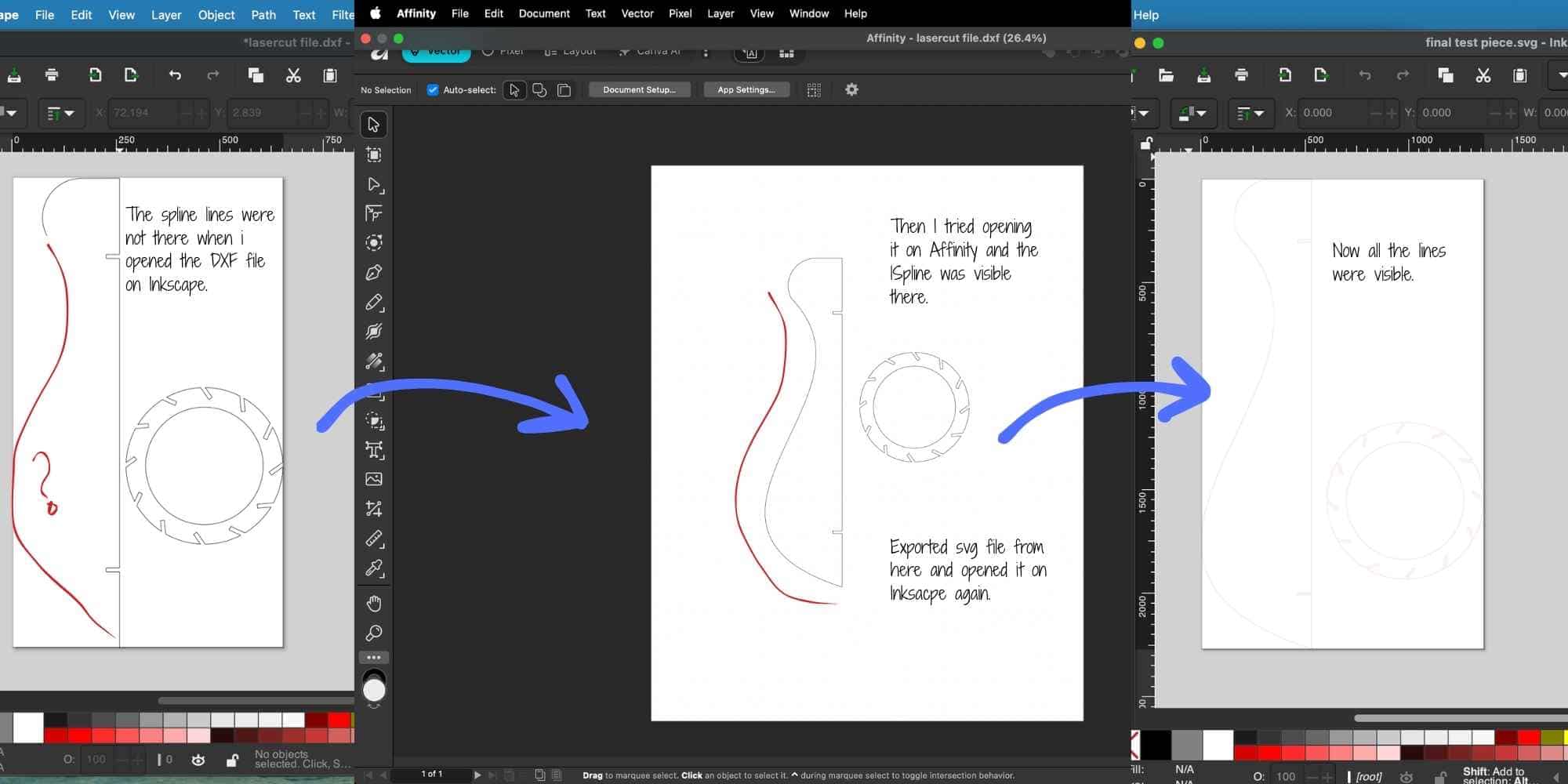
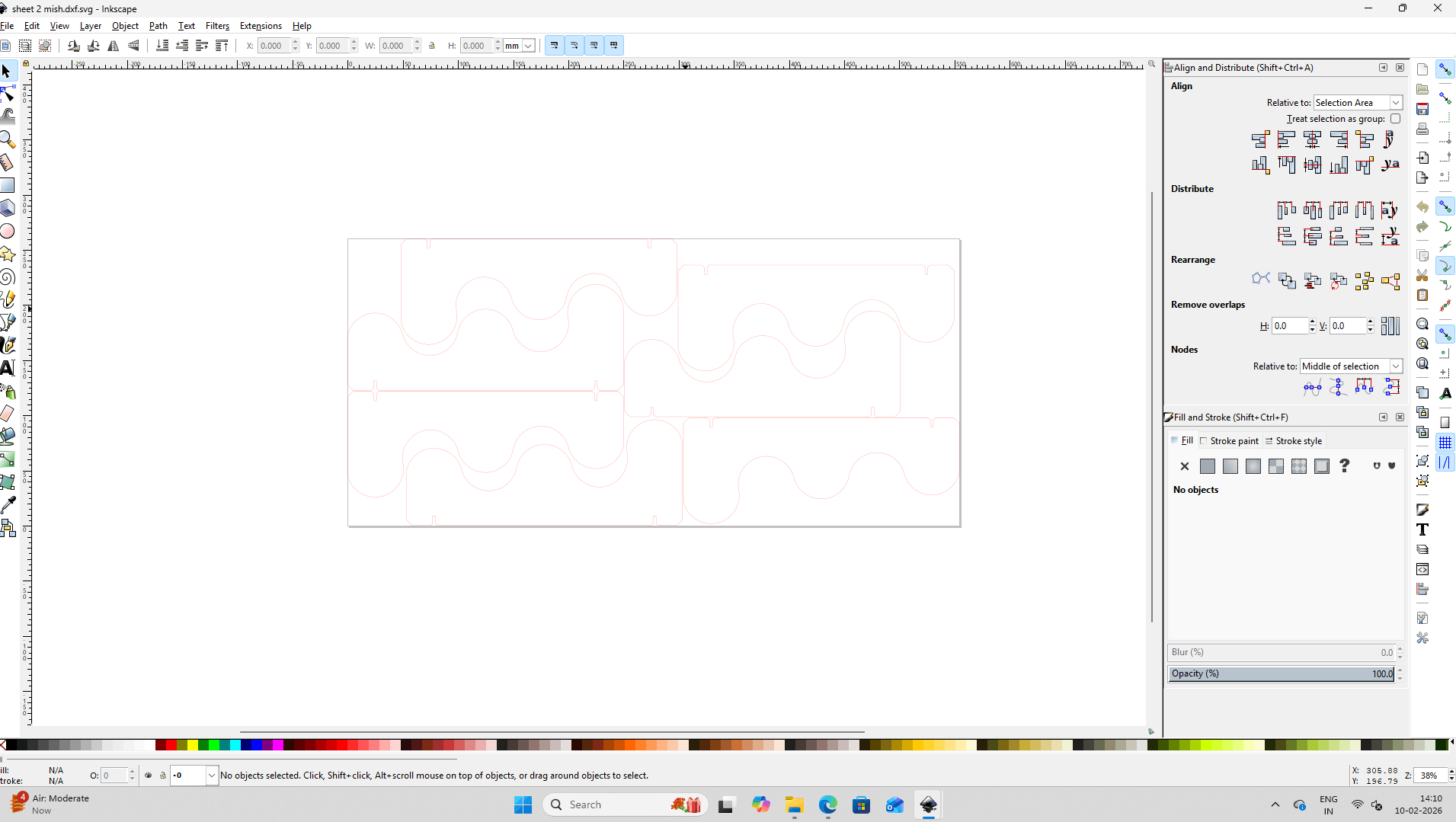
I used a spline to draw the curves, but it didn’t show up in the Inkscape file. Because of that, I had to open the file in Affinity, save it again as an SVG, and then open it in Inkscape to get it cut.
Once the file was opened on Inkscape, I changed the fill to none, set the stroke width to 0.1 mm, and changed the stroke color to red. The file was then saved in SVG format.
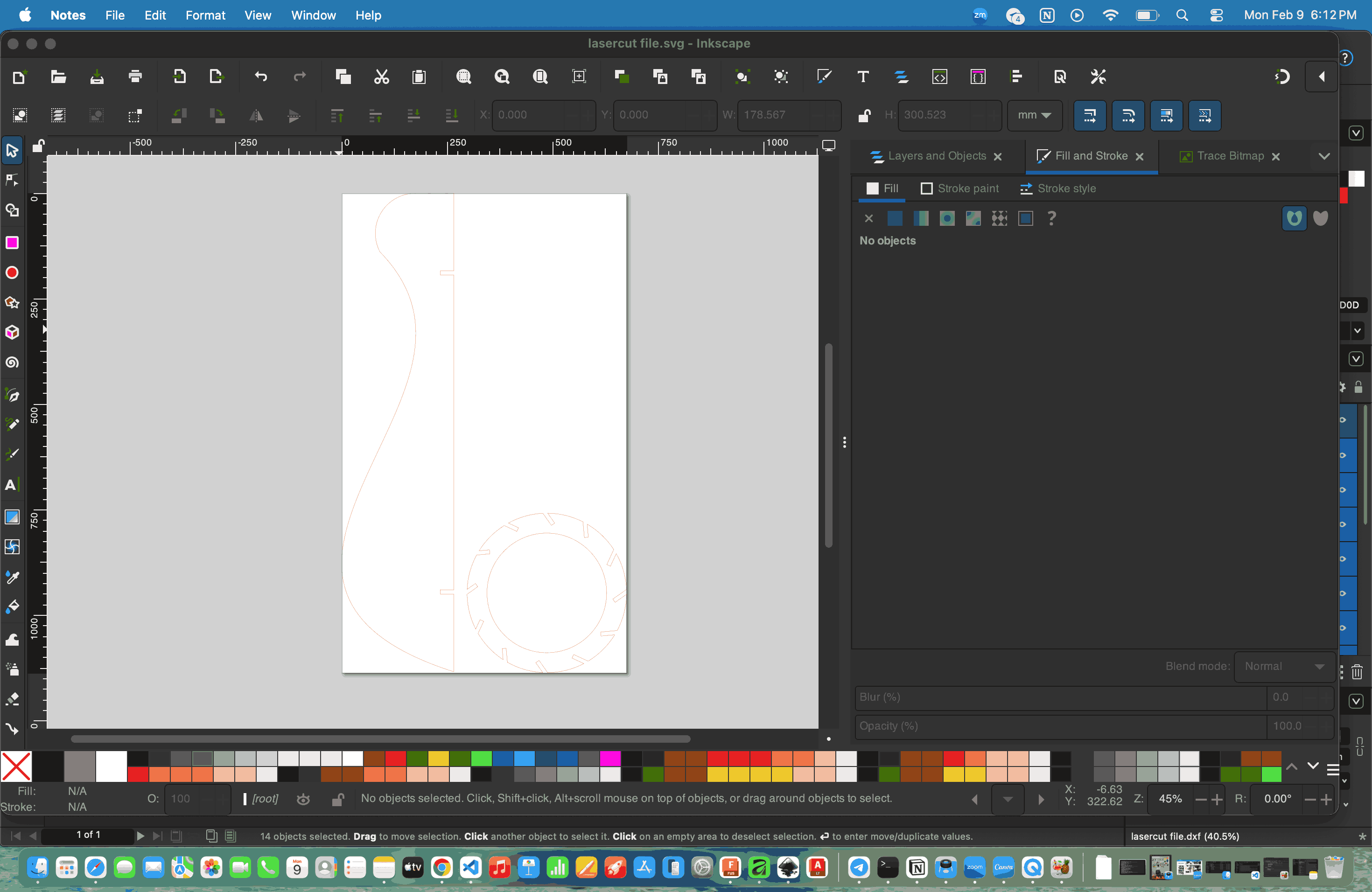
Using the Send Anywhere web application, I sent the SVG file to the computer connected to the laser cutter, where it was received and downloaded.
The file was then opened in Inkscape and sent to print, which opened it in Trotec Job Control.
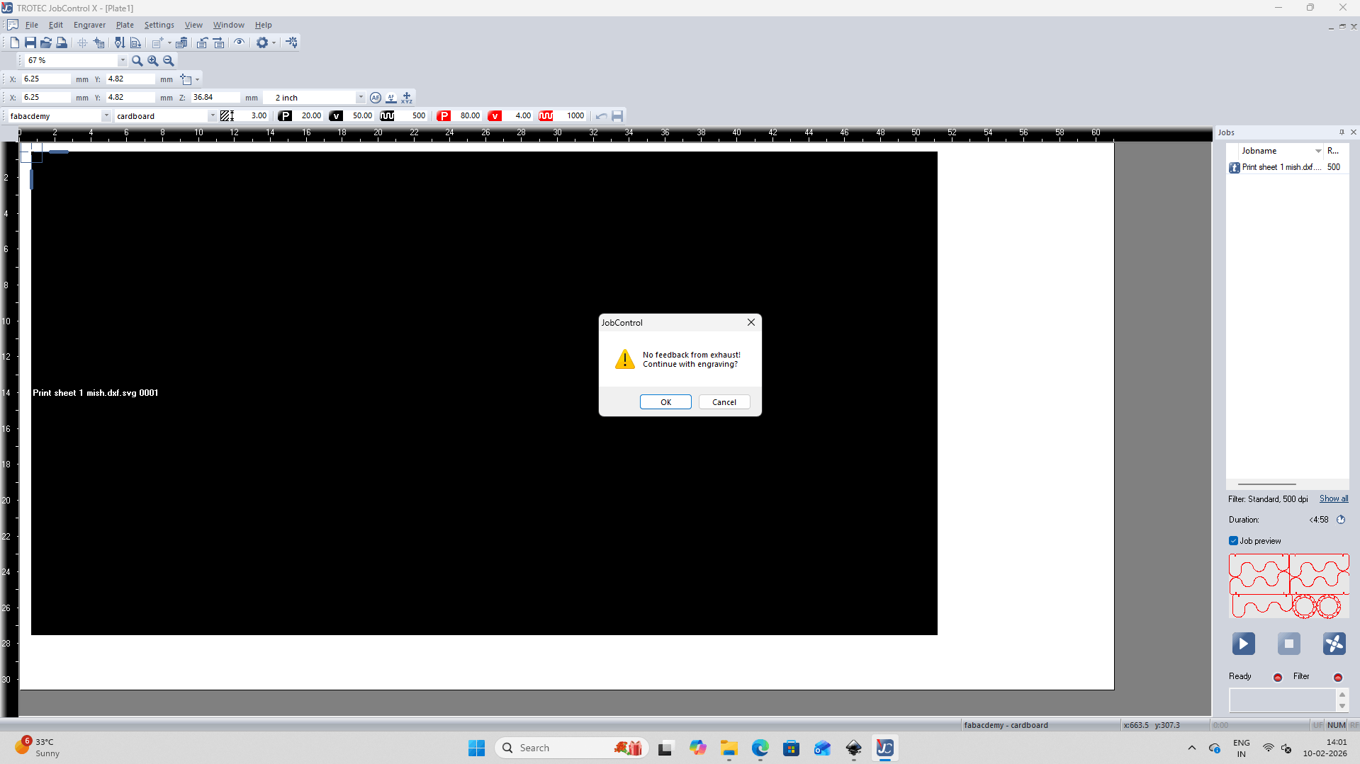
At this stage, the following parameters were set for Cardboard material - Cut: 80 power, 4 speed, 1000 Hz.
A pop-up dialog box then appears to confirm that the exhaust is on. Once approved, the play button can be clicked to begin the laser cutting process.
Insights
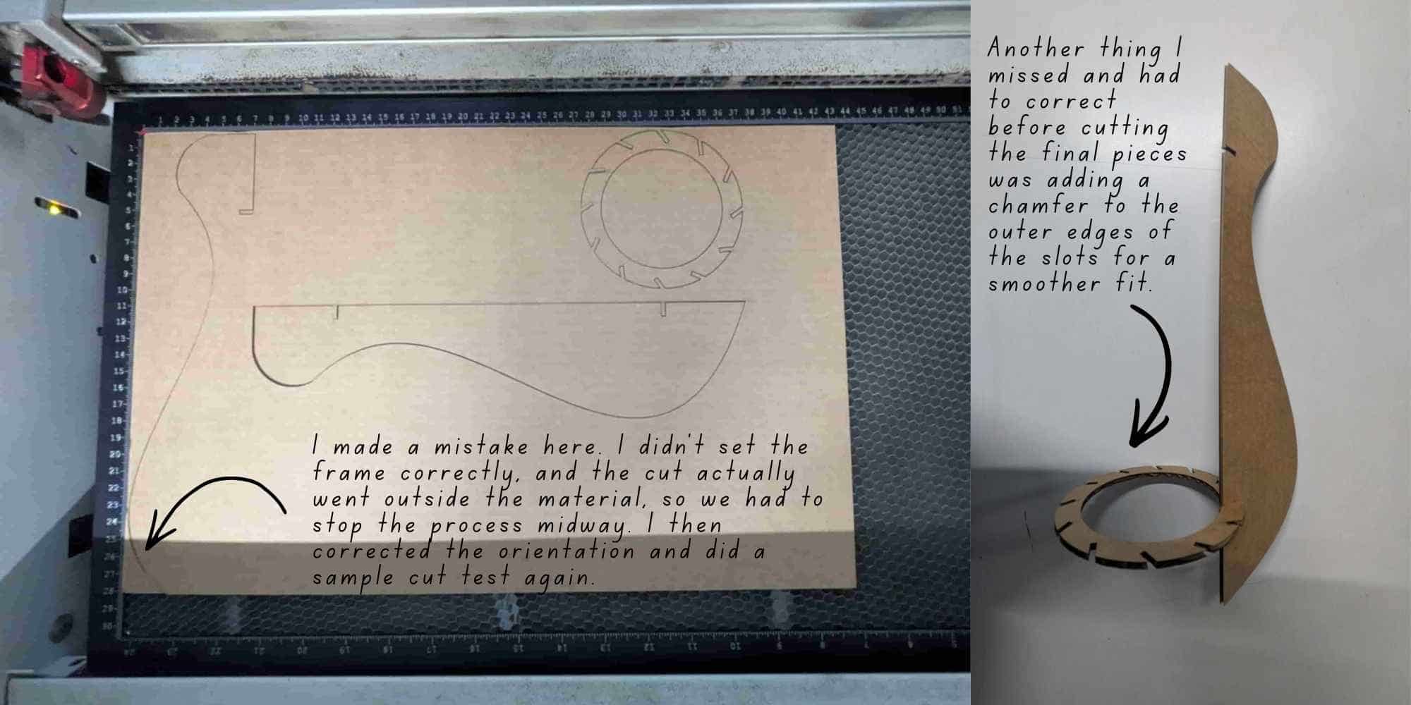
The step by step process of laser test cutting: DXF export >> Inkscape >> job control >> laser cutting >> fit testing couldn't be documented in detail as I got lost in finding the missing spline!
But a detailed documentation of the same process is done for the final production cut.
Now that I had my test piece ready, I moved on to making a few corrections. I added chamfers to the outer slot edges to ensure a smoother fit. I also wanted to try a different curve for the final piece.
Preparing the File for Final Production Cut
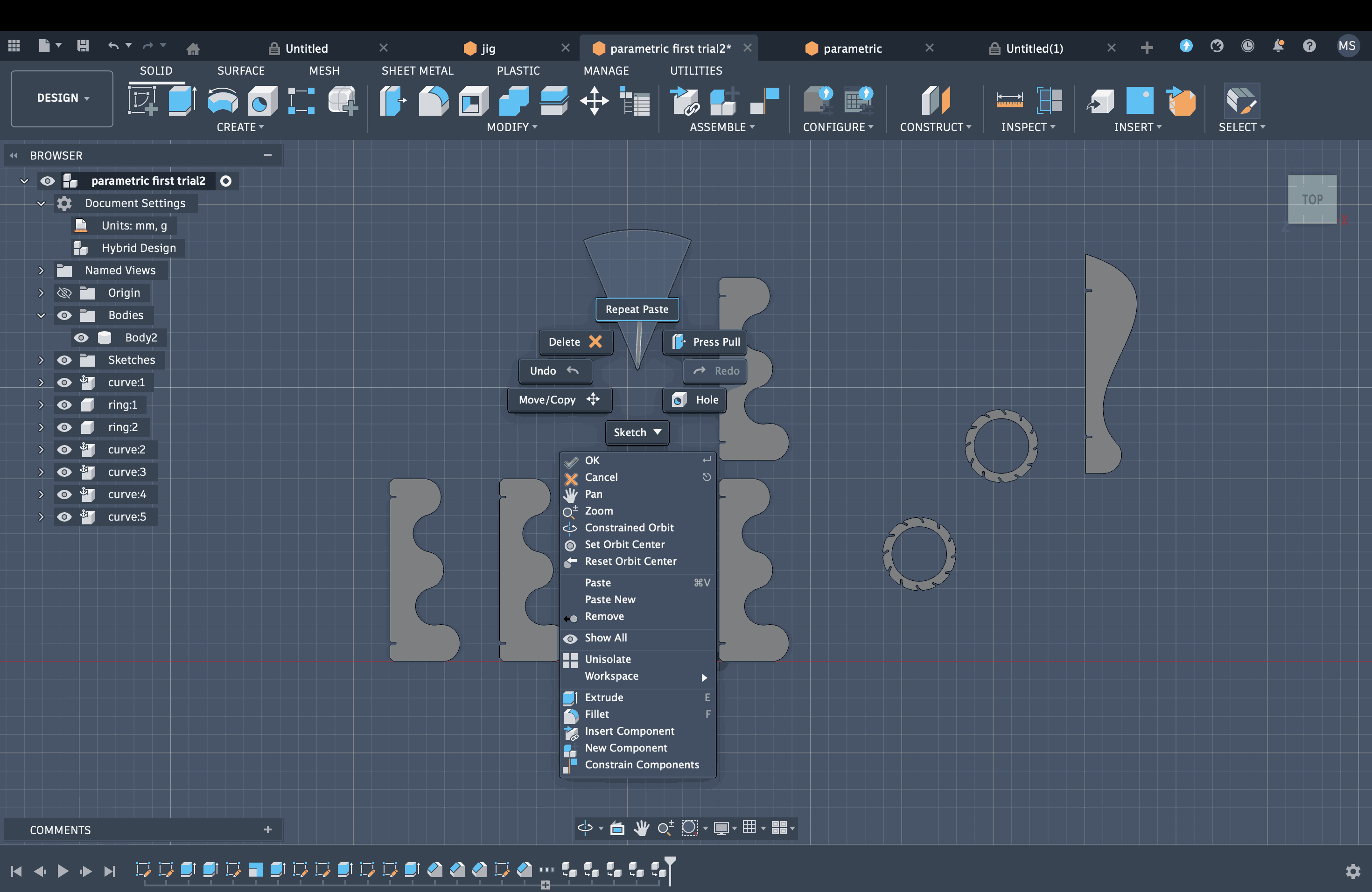
This time, I used arcs to create the curves, and all of them were visible when opened in Inkscape. Another thing I really had a hard time figuring out was how to properly set constraints for all these curves I had just created. I used the radius as a parameter for the arcs and applied dimensional constraints from the origin to the center of each arc. I also added equal constraints between the arcs and a perpendicular constraint between the base and the longest edge. I am not entirely sure how many of these constraints were actually required. There might have been a simpler or more efficient way to achieve the same result with fewer steps and less hassle. But I kept adding constraints and refining the sketch until the final drawing turned fully white and stopped moving, which meant it was fully constrained. The same parameters were applied since I was working on the same Fusion file.
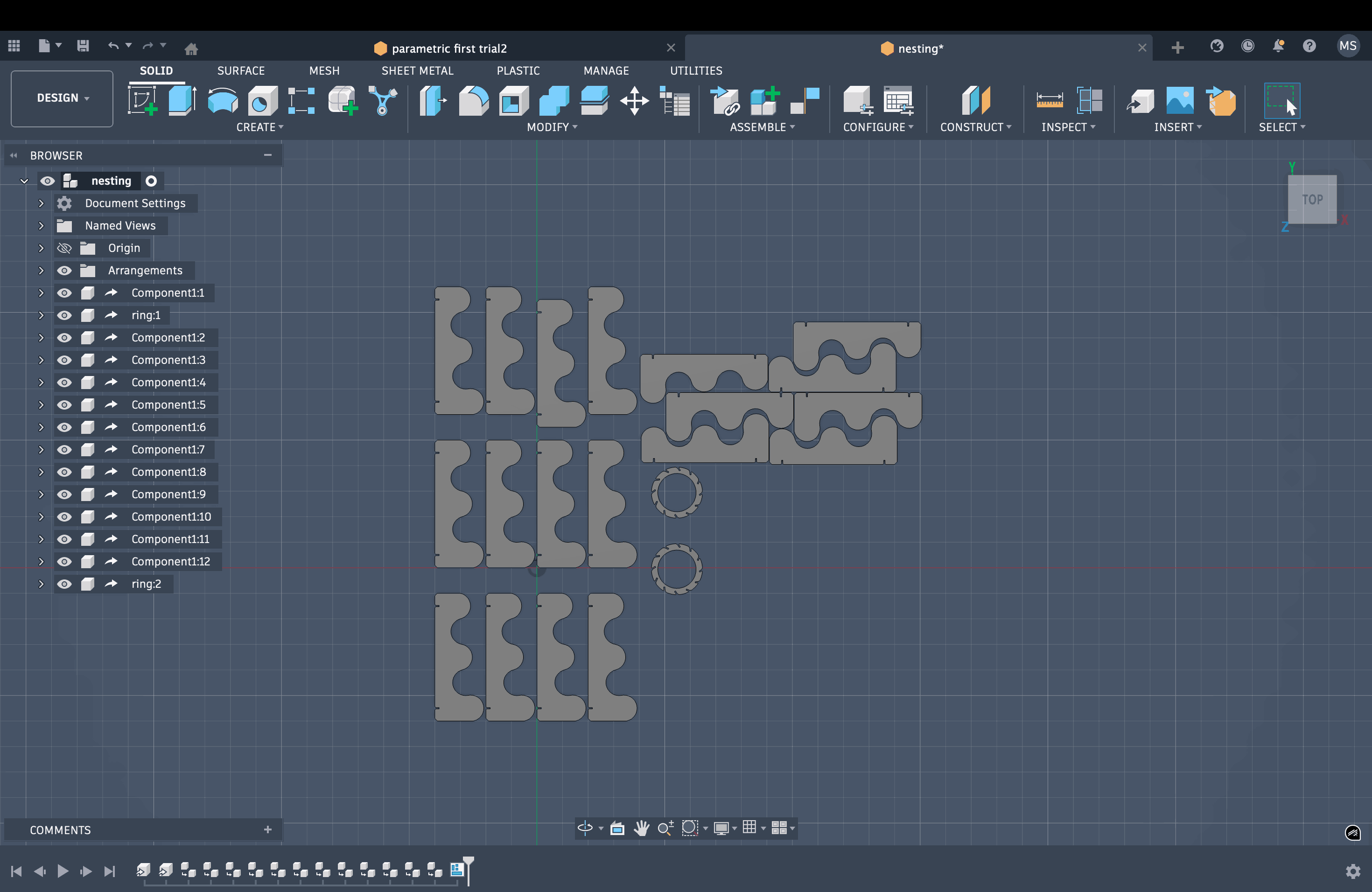
To group all the bodies, I first opened the file in hybrid mode. I then selected the bodies, right-clicked, and converted them into components. After that, I created the required number of copies of each component.
Nesting
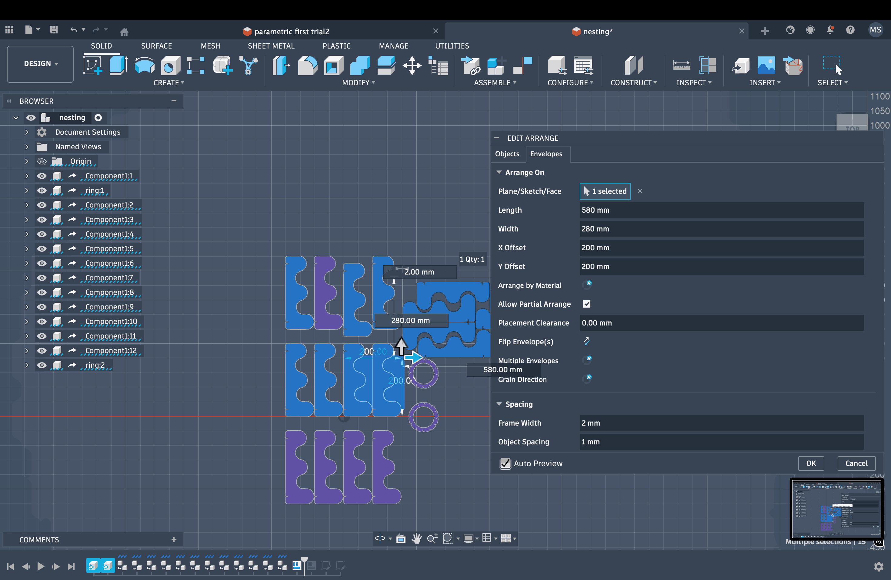
I then had to do nesting to ensure minimal waste and maximum utilization of the cardboard. For this, Fusion has a feature called Arrange. The path is Modify → Arrange. A pop-up window appears, first select all components in the Objects tab and then go to the Envelopes tab. It asks you to select the plane to be arranged.
Then the next setting is to mention the tenth and width of the material, in my case, cardboard that we are gonna cut our components in (available plate size). I measured the cardboard to 580 mm by 280 mm. Then I set the X and Y offset so that it doesn’t overlap the components. Frame width was set to 2 mm and object spacing to 1mm. Click Ok and it shows the nesting.
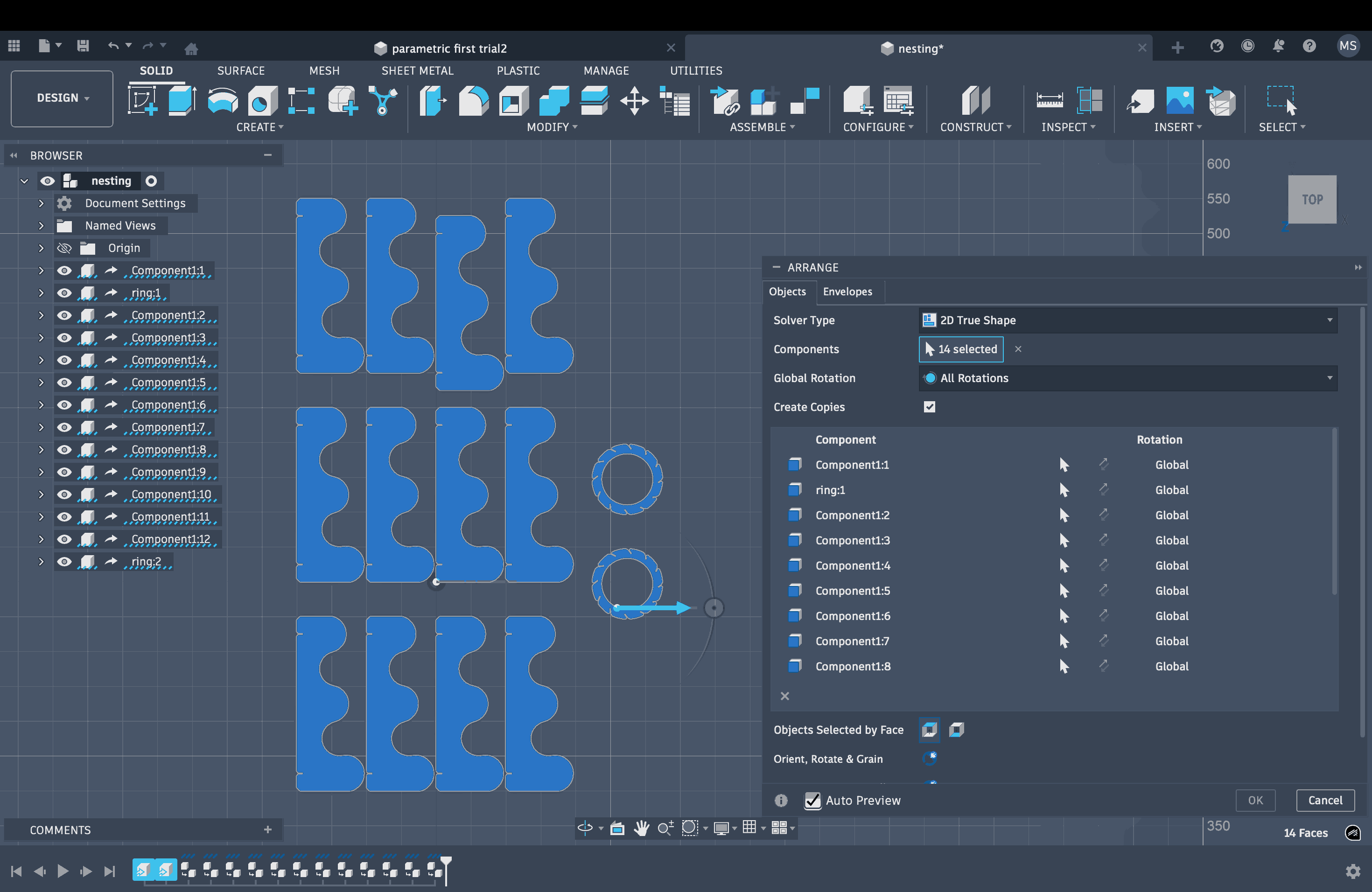
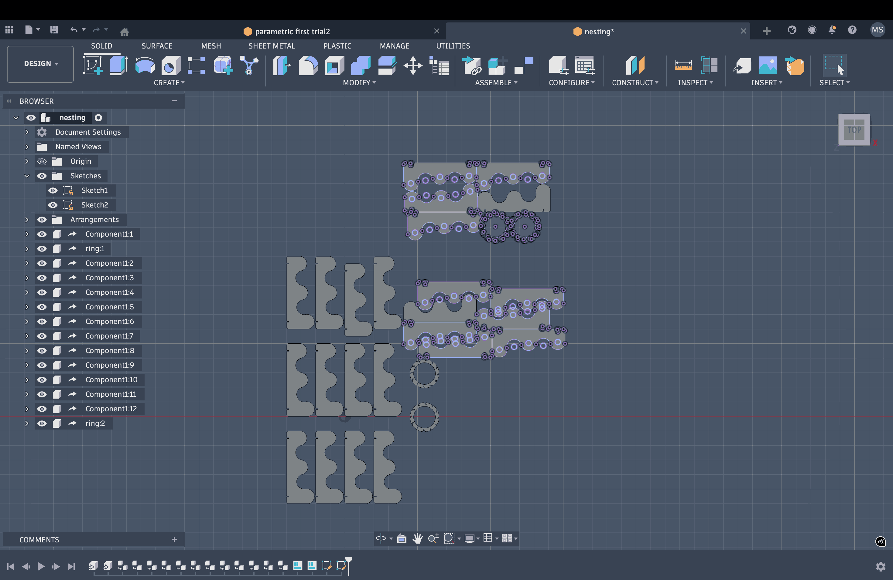
Now because I had 12 copies of my curved components and 2 copies of my circular component, not everything will fit it on one cardboard, so I repeat the steps with the rest of my components and created another nesting. Once that was ready, I selected one of the component, created a new sketch and projected the rest of the components, exported the sketch as dxf file. Repeated this with then other layout too.
DXF Export
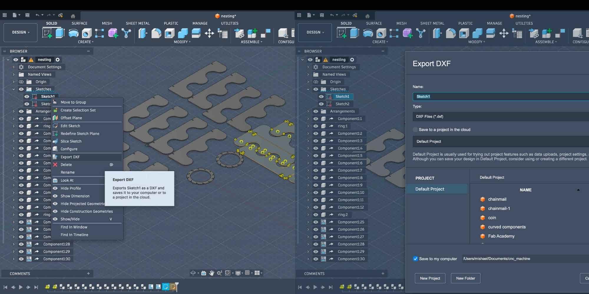
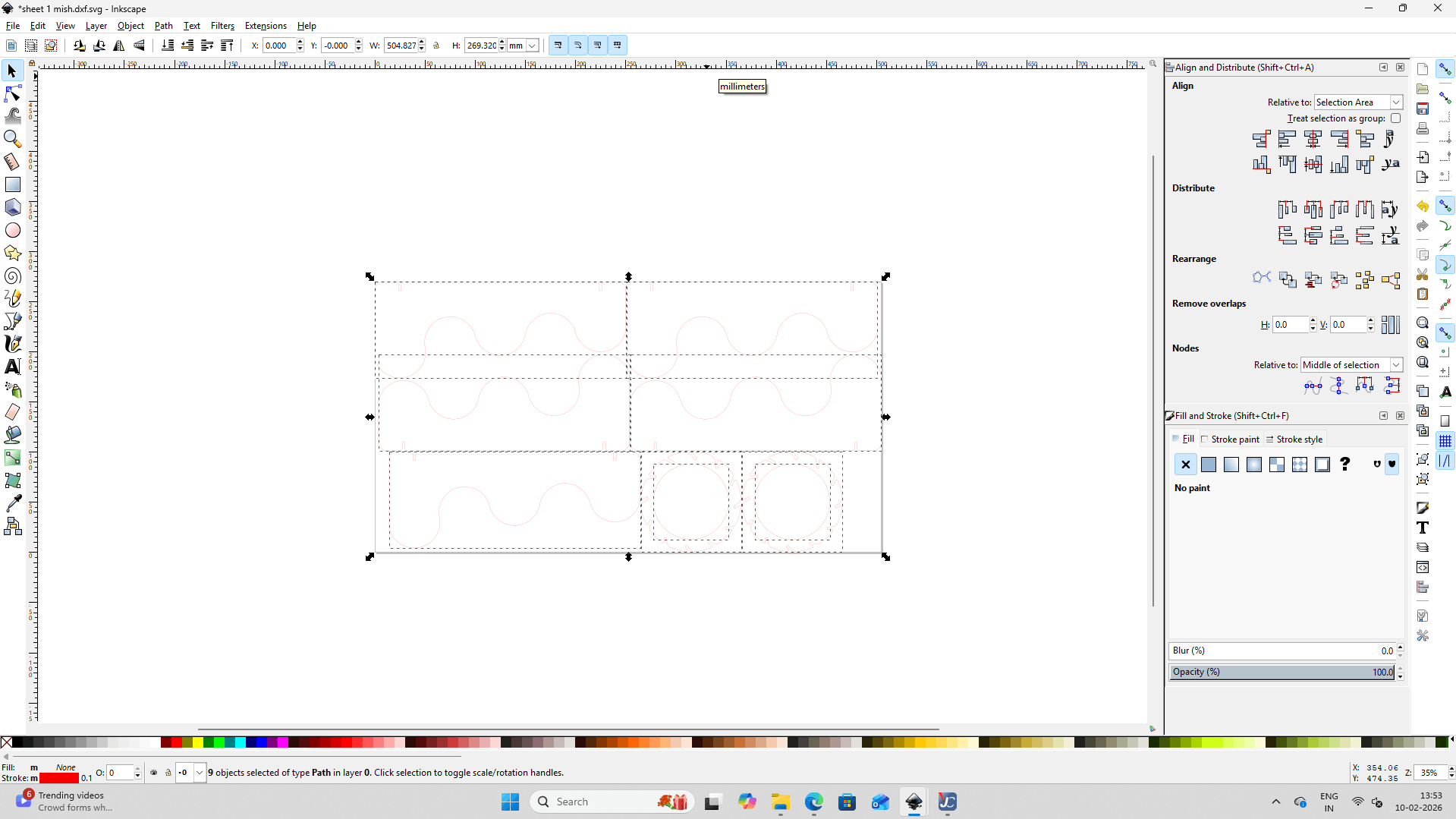
Inkscape
Opened the files on Inkscape, changed the fill to blank and stroke to 0.1 mm and color to red. Saved it as SVG and then send it to the system connected to Laser Cutting Machine using Send Anywhere.
From here we send the file to print and it opens up in Job Control
Job Control
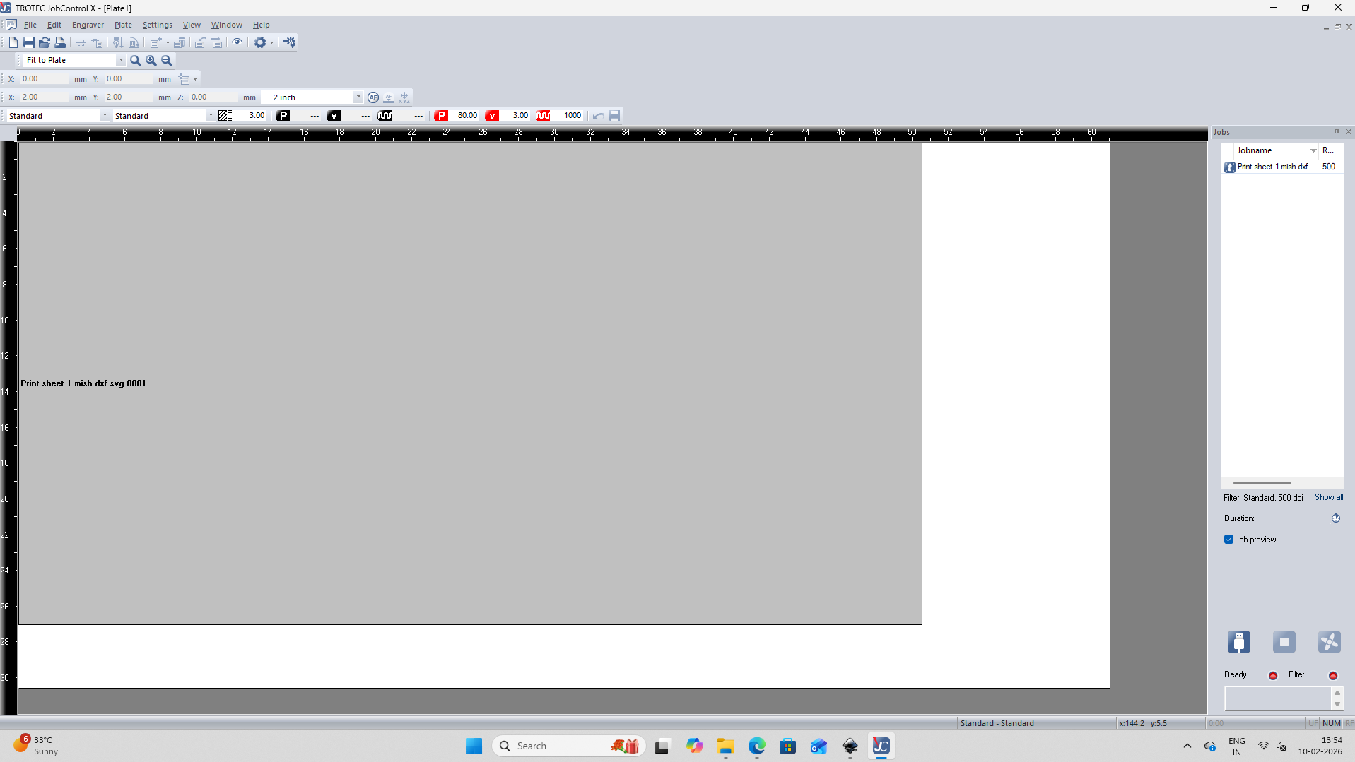
We had already set up the values for cardboard laser cutting when we did our group project.

Once the specifications are set and we press the play button to start cutting, a pop-up appears asking whether the exhaust is turned on.
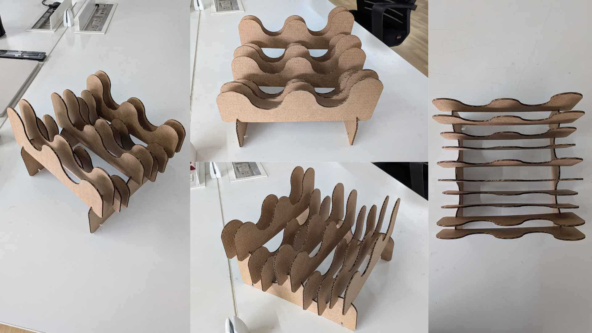
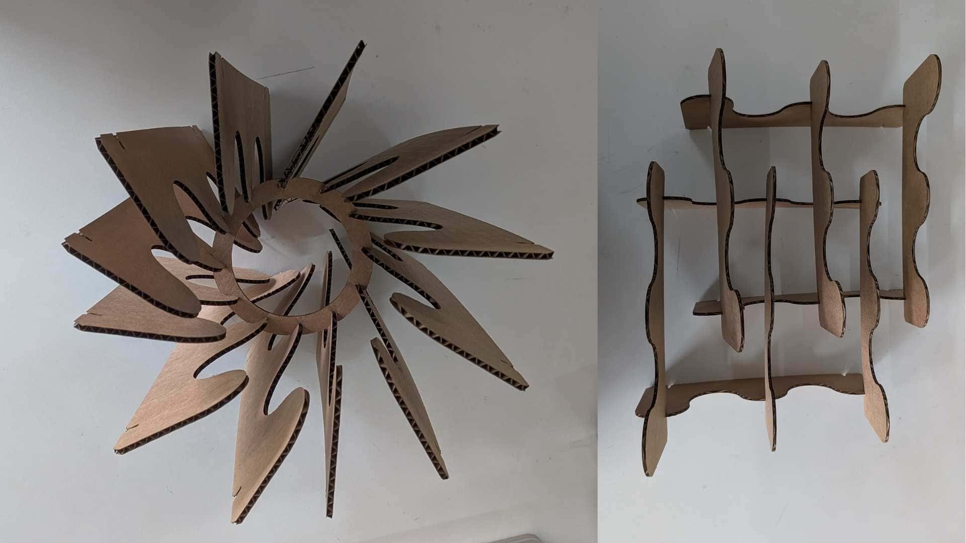
Laser Cutting and Press-fit Assembly
.jpg)
Hero Shots
X Tool Laser Engraving Experience
Saheen gave us an introduction and safety training on the Xtool F1 Ultra laser engraving machine. After completing our basic weekly tasks and documentation, we were encouraged to explore metal engraving. The machine available in our lab is the XTool F1 Mint Green Laser Engraver. It is a compact and lightweight laser engraver designed for fast and precise work. It combines a 10W diode laser and a 2W infrared laser, allowing engraving on a wide range of materials, including wood, acrylic, leather, glass, and metals such as gold, silver, and brass. It supports high engraving speeds and includes an HD live preview for accurate positioning.
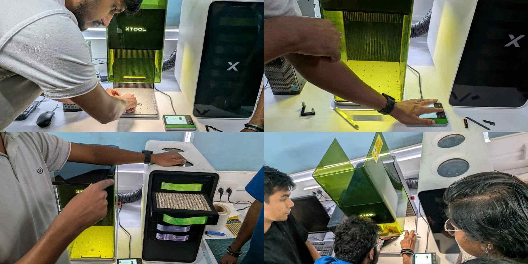
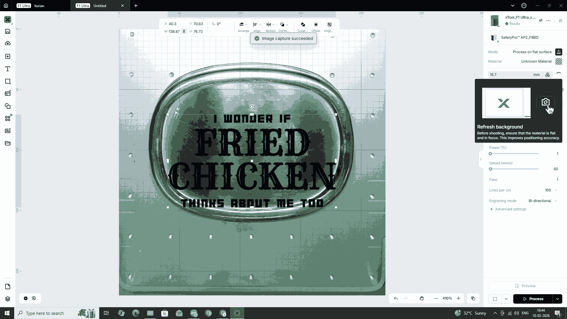
I placed the object, the lid of my tiffin box, on the XTool base. I then sent the prepared SVG file to the system connected to the machine using Send Anywhere and opened it in the XTool software. Since the lid was made of stainless steel, which is a reflective material, I had to manually adjust the focus on the XTool machine. The machine has an internal camera that captures the placement of the object, allowing precise digital positioning of the engraving file on the surface.
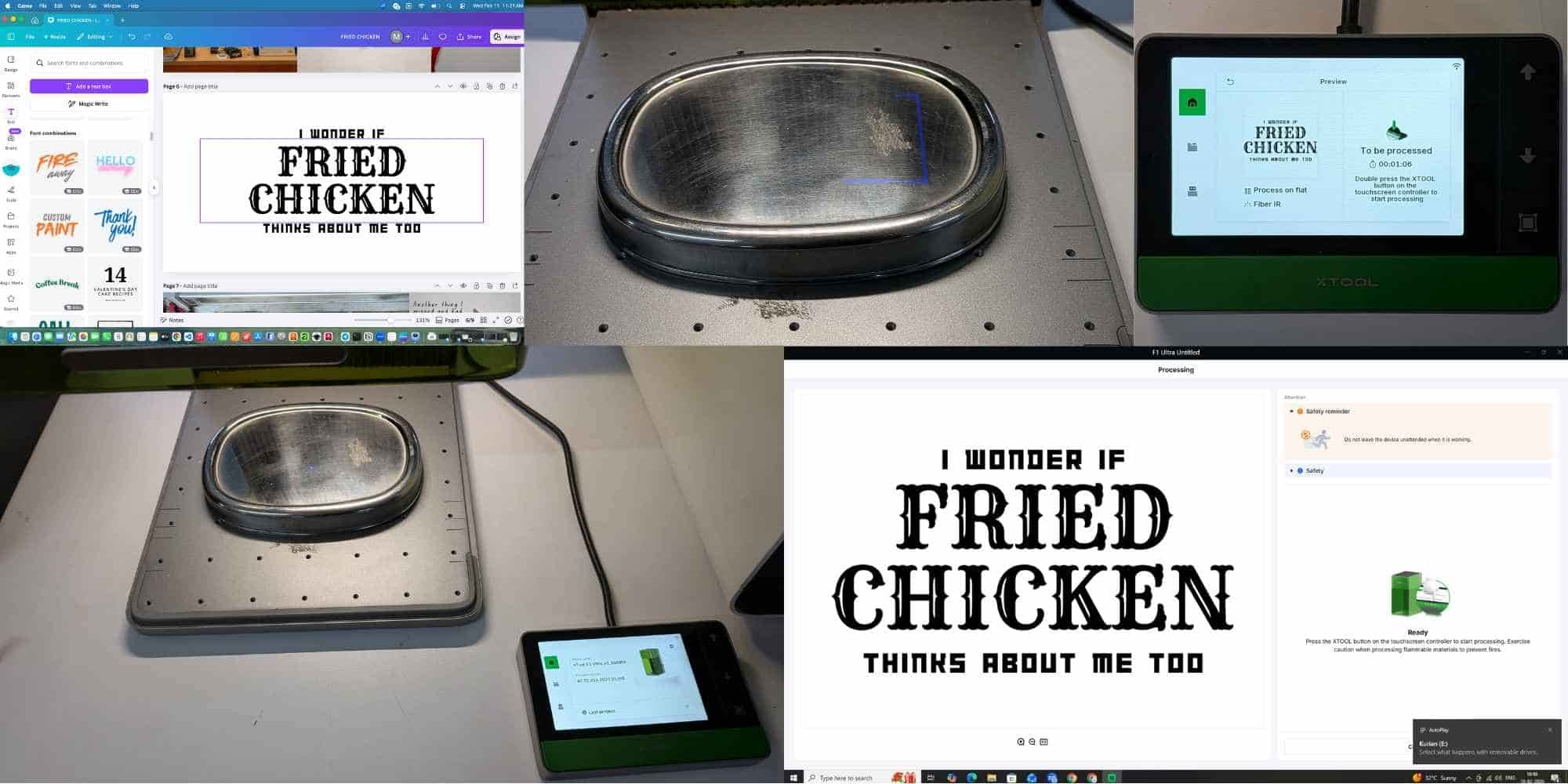
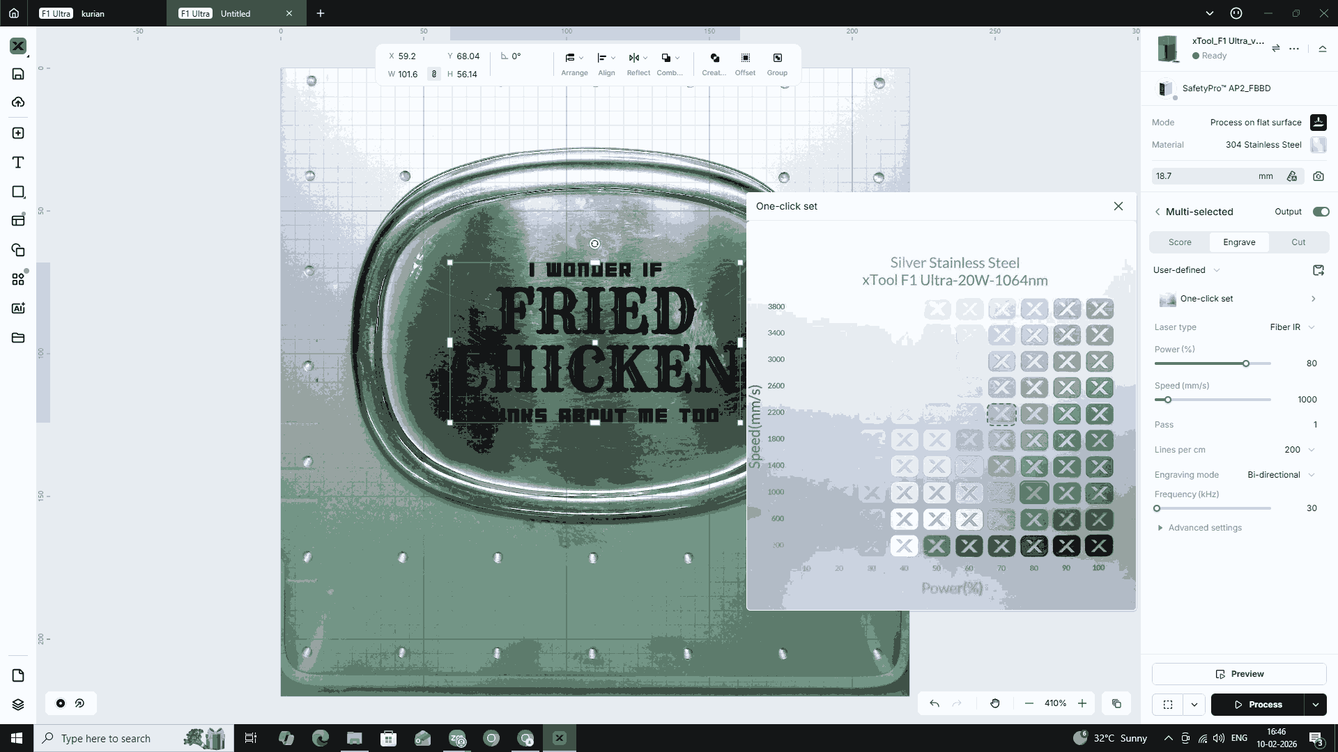
The file initially appeared in stroke mode, so I changed it to fill mode and selected the material as stainless steel. I then configured the appropriate power and speed settings. After setting these parameters, I checked the frame preview on the machine and made necessary adjustments through the system.
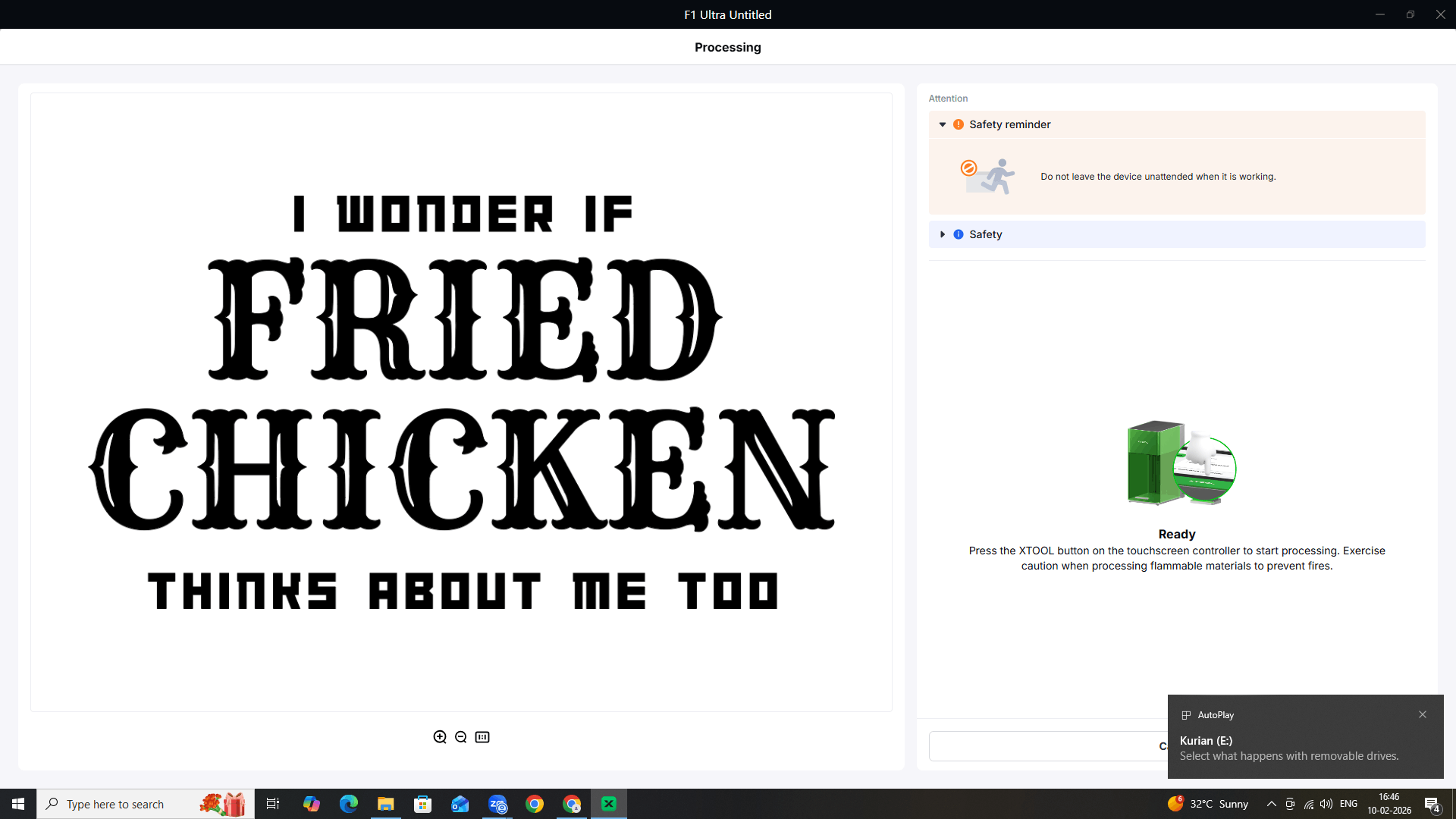
Once I was satisfied with the positioning and alignment of the file on the object, I closed the lid and pressed Enter twice to begin the engraving process.
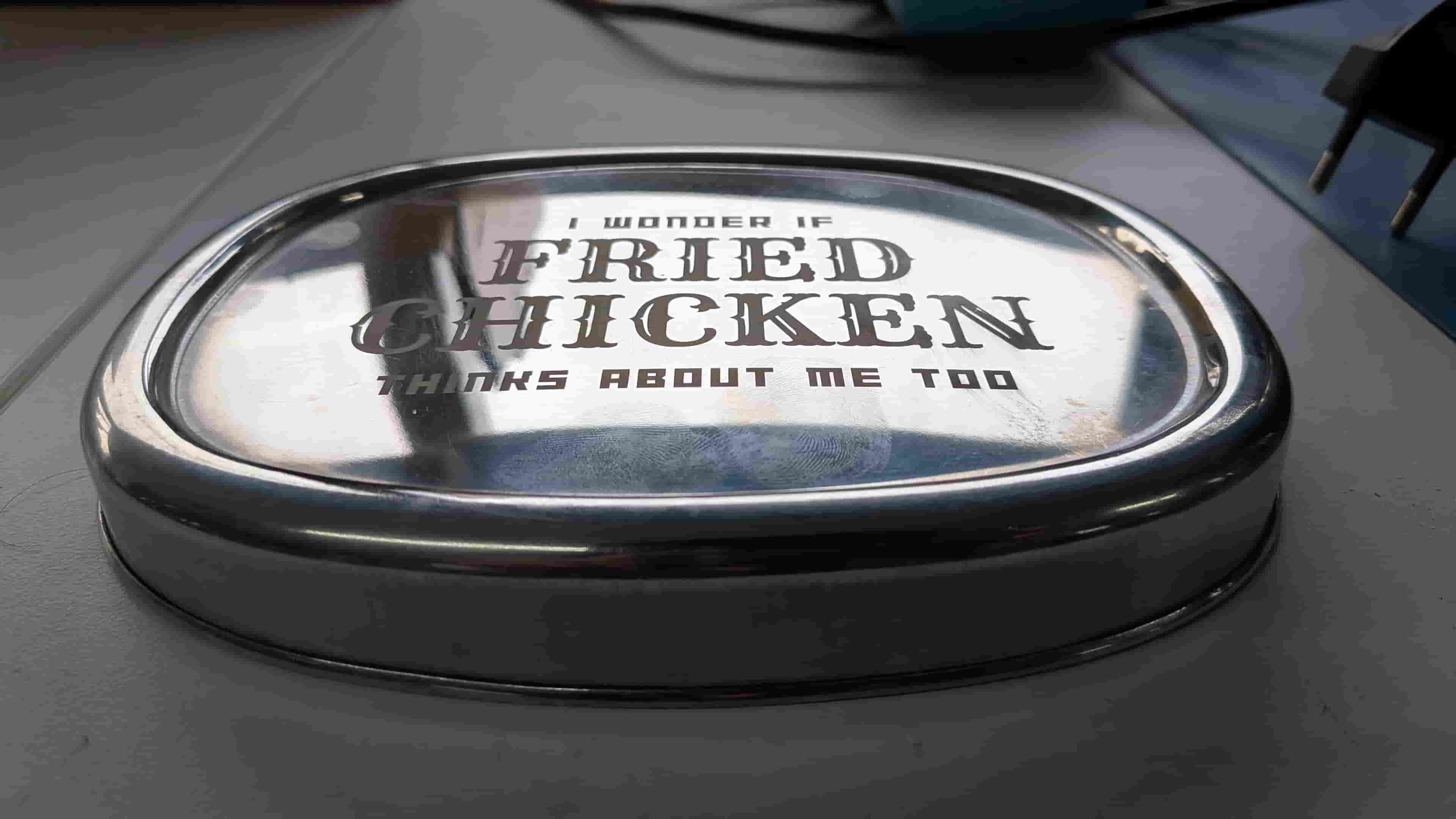
Hero Shot
Reflection
This was indeed a wonderful week, and I can already say that I am going to miss it a lot. The learnings from this week are going to be extremely useful in the future. I can already imagine a lot of potential projects and outcomes, now that we have learned the tips and tricks and gained first-hand experience in making things and not just conceptualizing them.