WEEK 08
Electronics Production
How the week started
I was finding my way through what a PCB is and how it is built. I referred to a few YouTube videos to widen my understanding, and it really did help me. I am able to follow the instructors with better ease than I did before. I hope to solder the PCB well.
How the week ended
Well, I was able to complete the assignment and test the board. I hope practice makes my soldering skills better. I am growing fond of the Modela MDX-20 3D Milling Machine
Week 08’s Assignment
Group assignment:
- Characterize the design rules for your in-house PCB production process and document the settings for your machine.
- Document the workflow for sending a PCB to a boardhouse.
- Document your work on the group work page and reflect on your individual page what you learned.
Individual assignment:
- Make and test a microcontroller development board that you designed.
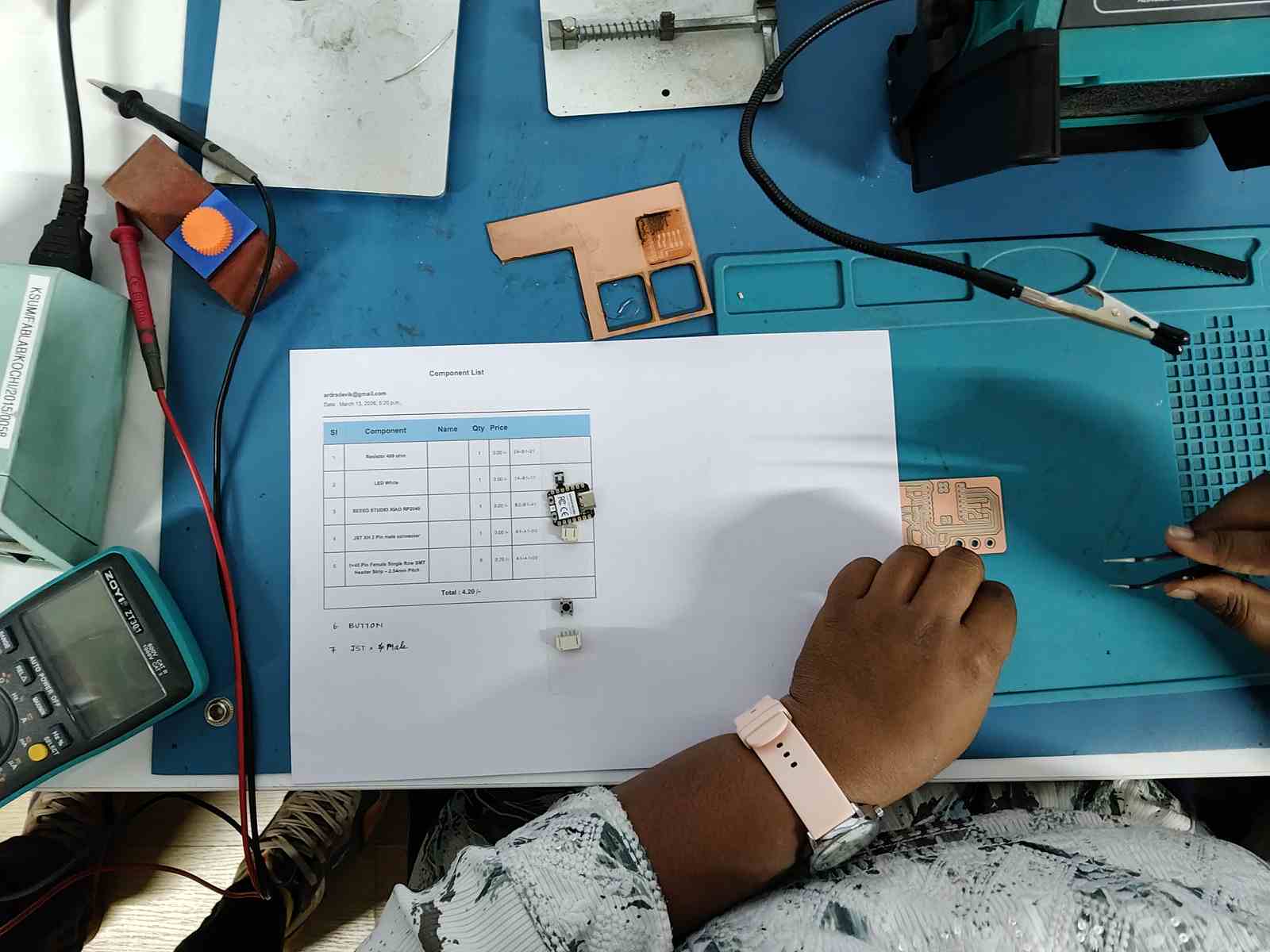
In Week 6, I had designed a PCB with the Module_XIAO-RP2040. This week I will be milling it to get the physical output, a workable model.
I had designed a button light in Week 6.
I opened the “button light” file in KiCad → PCB Editor.
File → Fabrication Outputs → Gerbers (.gbr)
This opens the Plot dialog box.
Generating Gerber files
.jpg)
.jpg)
.jpg)
.jpg)
The Gerber files have to be converted to PNG to send to the mill. For that conversion, there are 2 methods:
Method 1: Using the website to convert the Gerber files to PNG files.
Method 2: Using a plugin in KiCad to open directly to the website.
METHOD 1 Gerber2PNG website
We can go to the Gerber2png website, upload the Gerber files, and download the PNG files.
.jpg)
.jpg)
.jpg)
To view how the PCB will look using the Gerber files, we convert them to PNG format. For that, we can use an online Gerber-to-PNG converter. Fab Lab Kerala has created a website that does this.
Note: Select Double-Sided PCB if your PCB is double-sided. The layers are generated on the right side. We can download the files individually or as a ZIP file. Unzip the file after downloading.
Three files will be created:
- Outline layer
- Drills layer
- Traces
METHOD 2 Plug-in for KiCad
Fab Lab Kerala has also created a plug-in for KiCad. Gerber2Png Plugin can be downloaded from the site.
.jpg)
.jpg)
.jpg)
.jpg)
.jpg)
.jpg)
To view how the PCB will look using the Gerber files directly inside KiCad, we use the Gerber2PNG plugin. This allows us to generate PNG outputs without using an external website.
Note: Ensure the plugin is properly installed and enabled in the Plugin and Content Manager. The generated output will reflect the PCB layout similar to the online tool.
Three files will be created:
- Outline layer
- Drills layer
- Traces
Interactive HTML BOM Plugin
.jpg)
.jpg)
.jpg)
.jpg)
Milling PCB using Mods
Using Mods one can understand the toolpath, the offset paths. This is an overview of the workflow
.jpg)
.jpg)
.jpg)
.jpg)
Changes made in KiCad
.jpg)
.jpg)
.jpg)
.jpg)
.jpg)
.jpg)
File Outlook
.jpg)
.jpg)
.jpg)
.jpg)
.jpg)
Setting the Copper Clad Board
.jpg)
.jpg)
.jpg)
0.2mm V bit - Single flute - Commonly used for tracing
Mods Trace Workflow
.jpg)
.jpg)
.jpg)
.jpg)
.jpg)
.jpg)
.jpg)
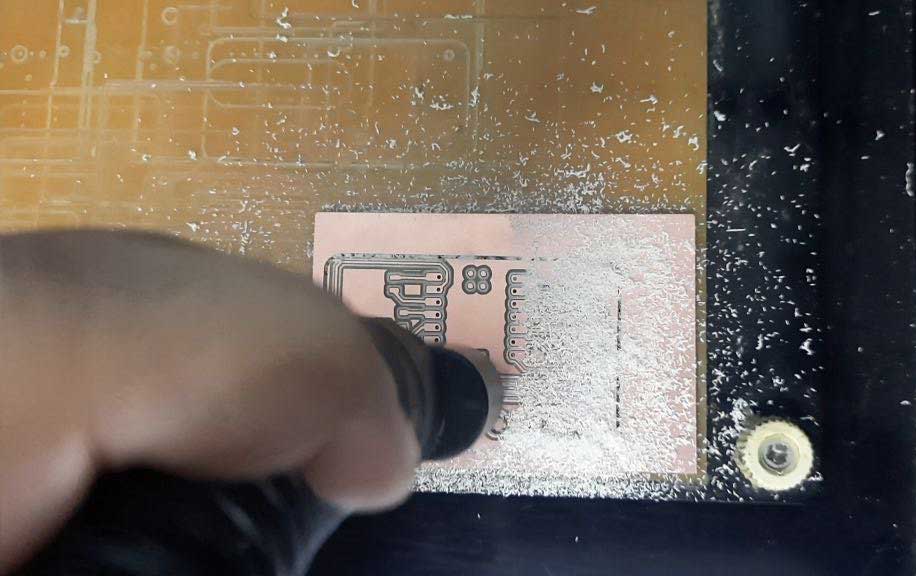
The process of vacuuming is done after each step to remove the PCB dust/debris.
0.8mm Flat end mill bit - Double flute - used for drilling and outline cuts
Drilling PCB
.jpg)
.jpg)
.jpg)
.jpg)
.jpg)
.jpg)
.jpg)
Fixing Trace Depth
.jpg)
.jpg)
.jpg)
.jpg)
PCB Outline Cutting
.jpg)
.jpg)
.jpg)
.jpg)
.jpg)
Removal of PCB
.jpg)
.jpg)
.jpg)
Sourcing Components
Fab Lab Kerala has an inventory Fabstash to place orders for components and also check their availability.
.jpg)
.jpg)
.jpg)
.jpg)
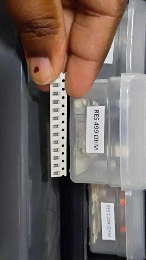
Physical Sourcing
Solder Workstation
The workstation has its own equipment, so one can peacefully complete the work without having to borrow anything around.
Equipment:
- Solder gun with hot gun
- Solder wire
- Wire to clean the solder is also placed below the gun to scrap the excess solder, if any, at the tip
- Fume extractor
- Helping hand
- PCB holder
- Sander
.jpg)
The workstation
Usage:
- The fume extractor extracts the fumes created when soldering. This is used in spite of wearing a mask.
- The helping hand is used to hold the PCB in place. I place mine on the silicone mat. Silicone mat has high temperature durability.
- PCB holder can also be used to hold the PCB in place.
- A sander is available to sand the copper clad slightly, to remove some layer off the clad so it grips the solder properly.
- Solder temperature is 350 degree or above.
- The hot air gun has its knob which is rotated to 2 or 3, the air pressure increases with the number.
- The components might be blown away if the force is increased.
- The hot air gun is used to loosen a component and a vacuum pump is used to remove the solder. Note: not advisable for small components.
- The solder gun has to be held properly.
.jpg)
Sand the PCB before soldering
Soldering Notes
Things to keep in mind when soldering
- Remove islands with a cutter
- Start from small components.
- Tweezers are your friends.
- Take out one component at a time or you will lose or misplace it, or the worst, place the wrong component.
- Heat the board for 2–3 seconds, then touch the solder wire.
- Get a volcano-shaped solder and not balls.
Things not to do when soldering
I soldered the 4 pins of a Vertical Pin Socket. The 5th pin was slightly off. I didn’t think much and pulled out the Vertical Pin Socket. Well, this should never be done. Lesson learnt! The pin parts stayed on the board as the black covering came off with the pliers. I removed the metal parts too, but then it was too late. 2 of the copper pads also came off.
Solution
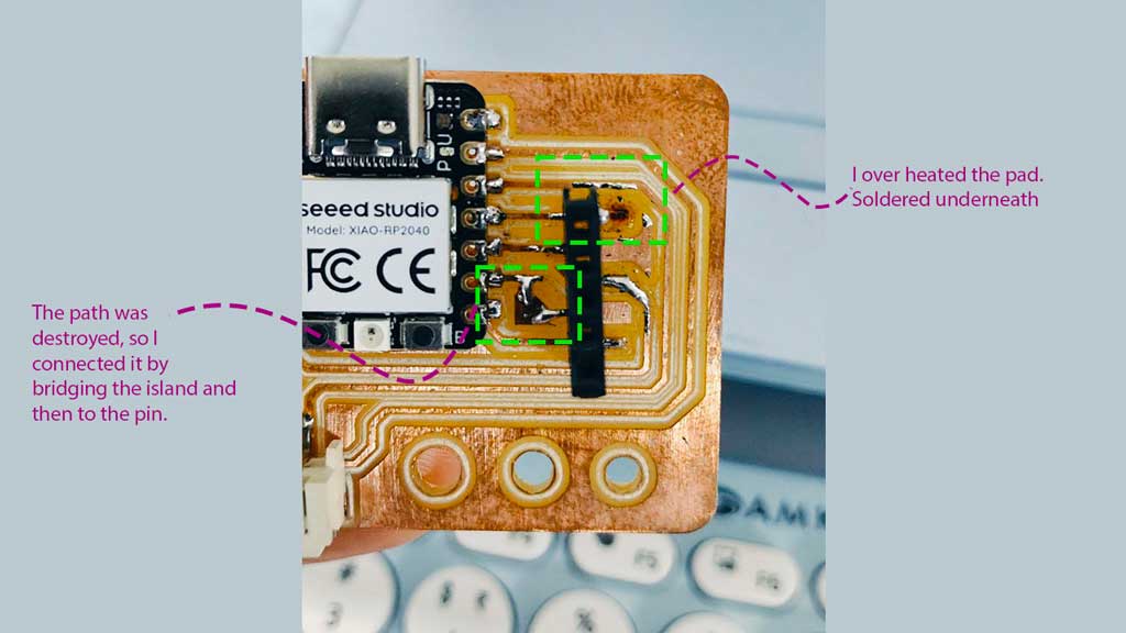
I soldered the path and the pin. I created an bridge connection with the other pin.
To make sure the connection was intact, I used a multimeter. I changed the setting to test conductivity and tested. The high-pitched sound confirms the conductivity.
Final look of the pcb
.jpg)
Testing
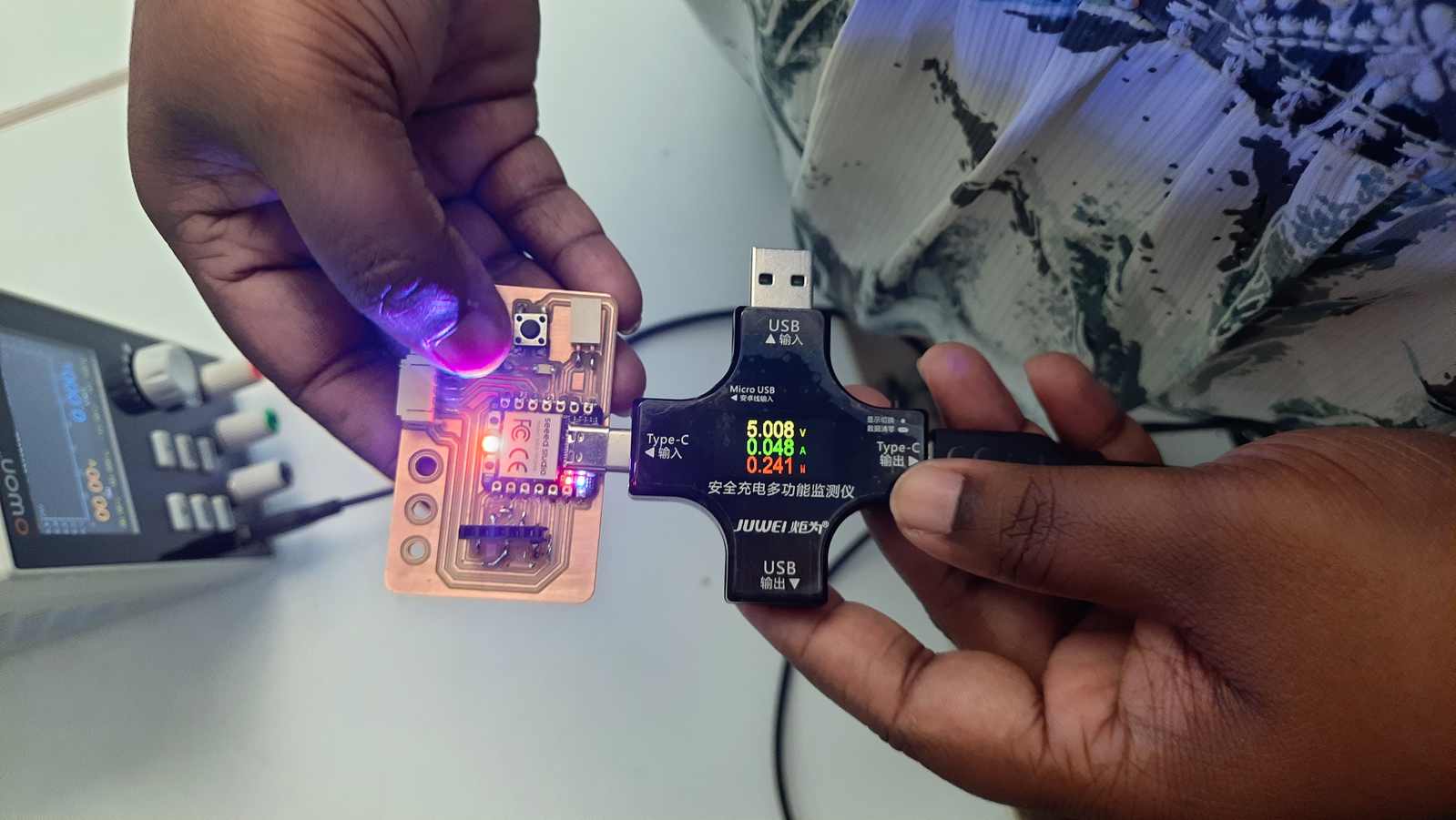
I used a USB Multimeter to test the power intake by the PCB. The XIAO needs 5V input. It is shown first.then the ampere used by the circuit should be under 0.500 Amp. If it's higher than 0.500 Amp, that means there is a short in the circuit. Power shows the power consumption.
Testing with Arduino
I used the same Arduino code from Week 4 to test the PCB. I had to change the ledPin number from D1 to D3 as there was a change in the ledPin I used.
.jpg)
Screenshot of the code used
Arduino code used
const int buttonPin = D0;
const int ledPin = D3;

bool isBlinking = false;
bool lastButtonState = HIGH;
unsigned long lastBlinkTime = 0;
const int interval = 500; // Blink speed in milliseconds

void setup() {
  pinMode(buttonPin, INPUT_PULLUP);
  pinMode(ledPin, OUTPUT);
  Serial.begin(9600);
}

void loop() {
  bool currentButtonState = digitalRead(buttonPin);

  // Check if button is pressed (transition from HIGH to LOW)
  if (currentButtonState == LOW && lastButtonState == HIGH) {
    isBlinking = !isBlinking; // Toggle the state

    // Print status to Serial Monitor
    Serial.print("LED Status: ");
    Serial.println(isBlinking ? "BLINKING" : "OFF");

    if (!isBlinking) digitalWrite(ledPin, LOW); // Ensure LED is off when disabled
    delay(50); // Debounce delay
  }
  lastButtonState = currentButtonState;

  // Handle the blinking without blocking the code
  if (isBlinking) {
    if (millis() - lastBlinkTime >= interval) {
      lastBlinkTime = millis();
      digitalWrite(ledPin, !digitalRead(ledPin)); // Invert current LED state
    }
  }
}