Living in a world saturated with smart gadgets, I realized I’ve always been a passive consumer, never truly curious about the
mechanics behind them. It’s a strange feeling to be surrounded by technology every day yet have no idea how it actually functions.
How the week ended
It concluded with me gaining a foundational understanding of embedded programming. Although I didn’t get
the opportunity to explore it in depth, watching my batchmates demonstrate what could be achieved truly sparked
my interest. From lighting up a series of LEDs to working with OLED displays, and even creating simple games on
LED strips and panels, I began to see the exciting possibilities that embedded programming offers.
Week 04’s assignment
Group assignment:
• Demonstrate and compare the toolchains and development workflows for available embedded architectures.
• Document your work to the group work page and reflect on your individual page what you learned.
• Browse through the datasheet for a microcontroller.
• Write and test a program for an embedded system using a microcontroller to interact (with local input &/or output devices)
and communicate (with remote wired or wireless connections).
My Understanding of Embedded Systems
View AI Prompt Used
Create an illustration of a cat confused about embedded systems.
At the beginning of this week, I found myself trying to understand the concepts being taught and the expectations of the assignment.
After two days of exploration and valuable guidance from our instructor, I was able to gain clarity and develop the work presented below.
In simple terms, an embedded system is a specialized controller designed to perform a dedicated function.
Unlike a general purpose computer that can run many different programs, an embedded system is built for a specific task combining hardware and software into a single, cohesive unit.
The Hardware:
This includes the physical components, such as LEDs, sensors, and switches. In a basic circuit,
a switch simply closes a loop to provide power.
The Microcontroller (The "Brain"):
This is where the logic of the system operates. The microcontroller allows us to bridge the gap
between physical components and computational control.
The Software (Firmware):
By writing code and uploading it to the microcontroller, we can define exactly how the hardware behaves.
Instead of a light simply being "on" or "off," we can program complex patterns, time durations, or responses
to environmental inputs.
Group assignment
We did a simple action of lighting a LED using 4 different boards using its board development environment. The comparison is based on its user experience
Board
Development Environment
Programming Level
Build Process
Flashing Method
Blink Implementation Style
Observed Complexity
Arduino Q (UNO R4 WiFi)
Arduino IDE / Arduino Cloud
High-level C++
Automatic compile & upload
USB (One-click)
digitalWrite()
Very Easy
ESP32-C6
VS Code + ESP-IDF
C / Assembly (RISC-V)
idf.py build (manual build system)
idf.py flash
Direct GPIO register control
High
ESP32-S3-DEV-KIT
VS Code + PlatformIO
C++ (Arduino Framework)
PlatformIO build system
USB via PlatformIO
digitalWrite() / NeoPixel library
Medium
ATtiny44/84
Microchip Studio + AVR-GCC
Embedded C
Compile → Generate HEX
AVRDUDE + ISP Programmer
Direct PORT register manipulation
Medium (Low-level)
Arduino IDE was the most beginer friendly to use and learn.
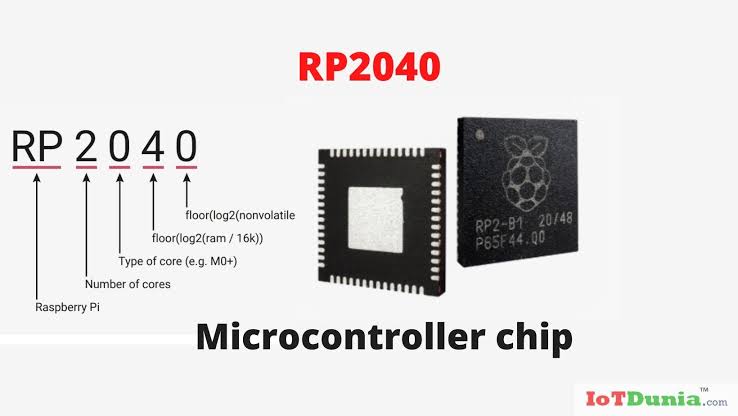
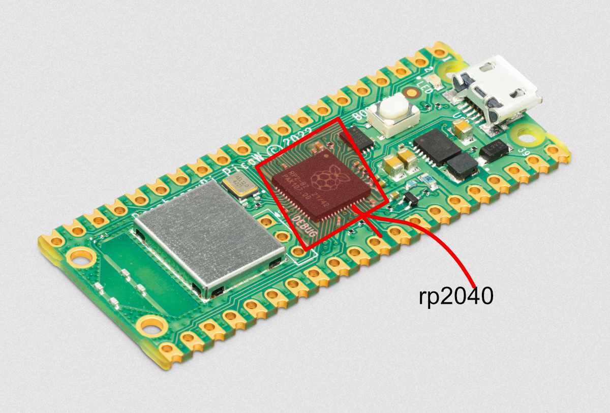
So, RP2040 is a microcontroller designed by Raspberry Pi. It is famous for its Programmable I/O (PIO) subsystem, which allows users to create custom hardware interfaces.
The post-fix numeral on RP2040 comes from the following:
Number of processor cores (2)
Loosely which type of processor (M0+)
floor(log2(RAM / 16k))
floor(log2(non-volatile memory / 16k)) or 0 if no onboard non-volatile storage
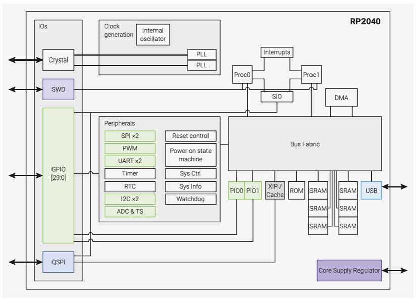
A system overview of the RP2040 chip
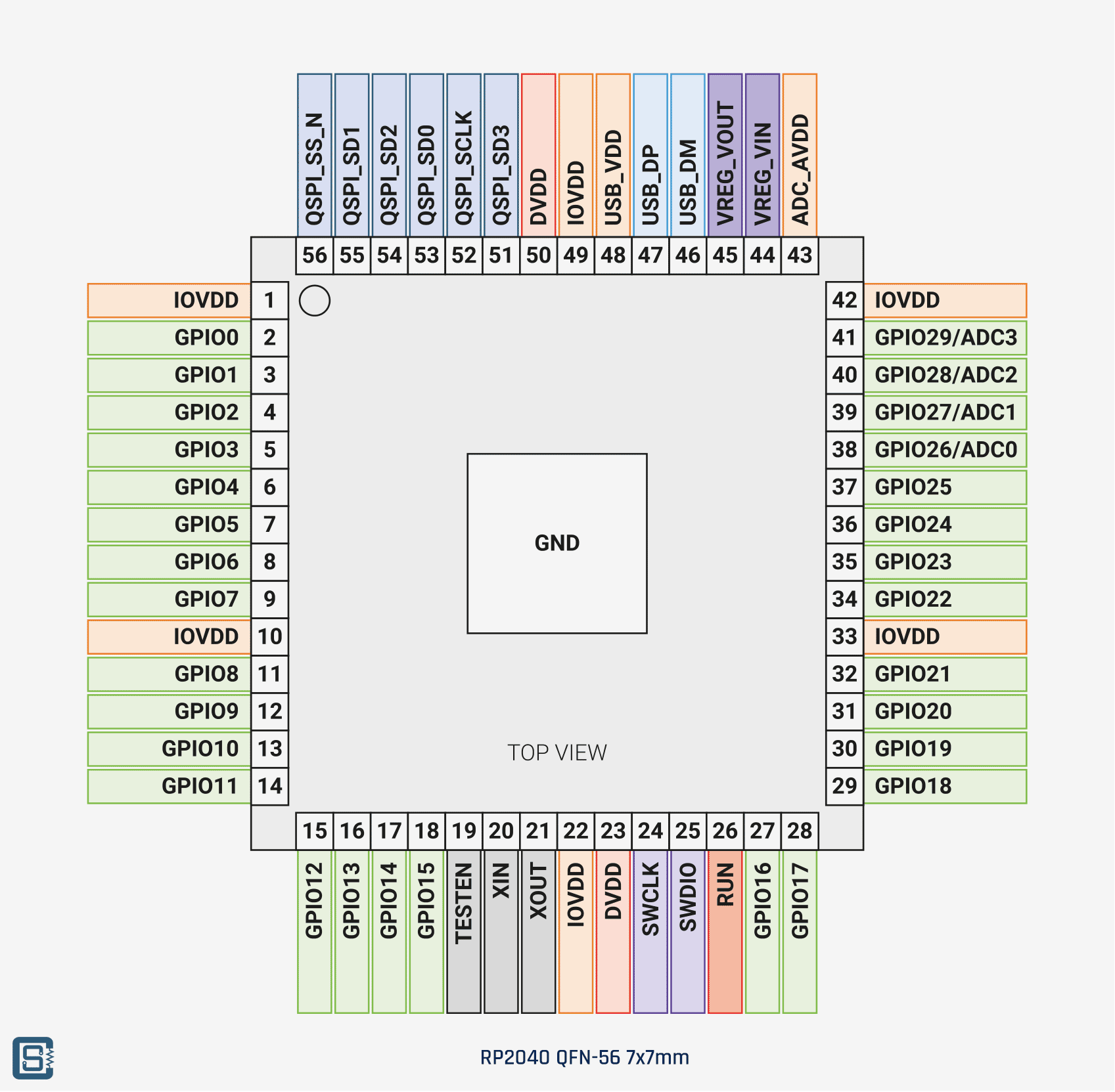
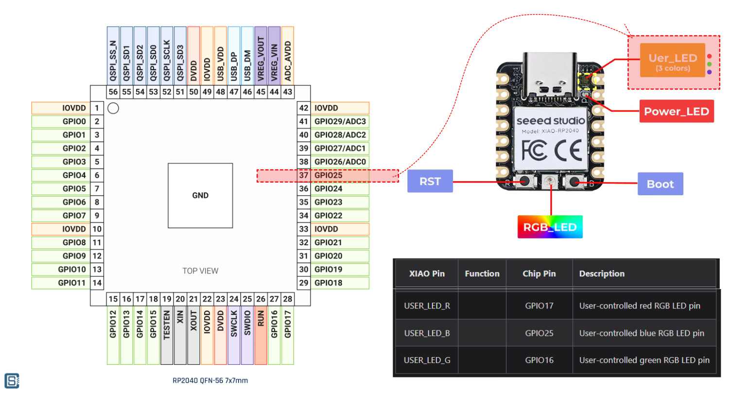
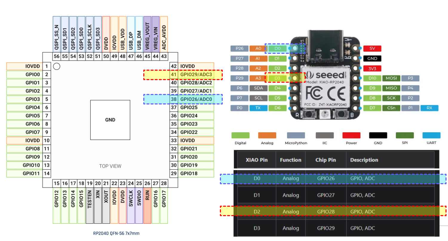
RP2040 Pinout for QFN-56 7x7mm (reduced ePad size)
the RP2040 chip has 30 GPIO pins in total. GPIO stands for General Purpose Input Output. What makes the RP2040 interesting is that these pins aren't locked into one job. The datasheet describes this as pin multiplexing, meaning each GPIO can be assigned to different functions depending on what the code tells it to do. the chip also has Programmable I/O (PIO) blocks which is exactly how the WS2812 neopixel protocol is handled without needing special hardware support. a aatte machine handl;es the neopixel. state meachien - is oemthing that always remaisn in 1 state ata a time and can move between states based on the rules given to it.
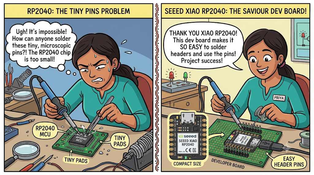
Now, using this MCU directly would be difficult to solder and program. So, for easy access to the pins and programming, we have developer boards. These allow prototyping, testing, and building electronic projects.
rp2040 micro controler has pins but not solderable by people. To make it easy developer boards come here as saviour making the the pins solderable. create a fun comic image to show this. 2 parts,
part 1 showing the rp2040 microcontroler hard to solder and 2nd part it becomes easy to solder because of the seeed xiao rp2040 developer board and that the image has to be factually correct. Fun and easy to understand.
Landscape image , an indian woman as character
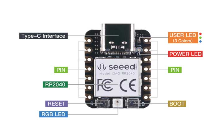
Now let’s meet developer boards
Raspberry Pi Pico : The original developer board . Source
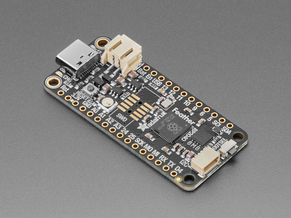
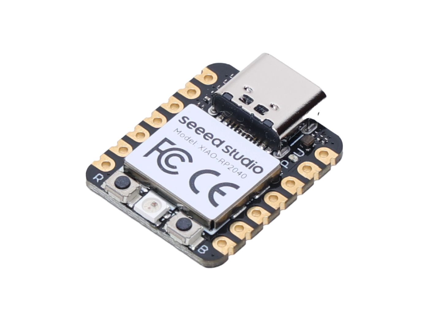
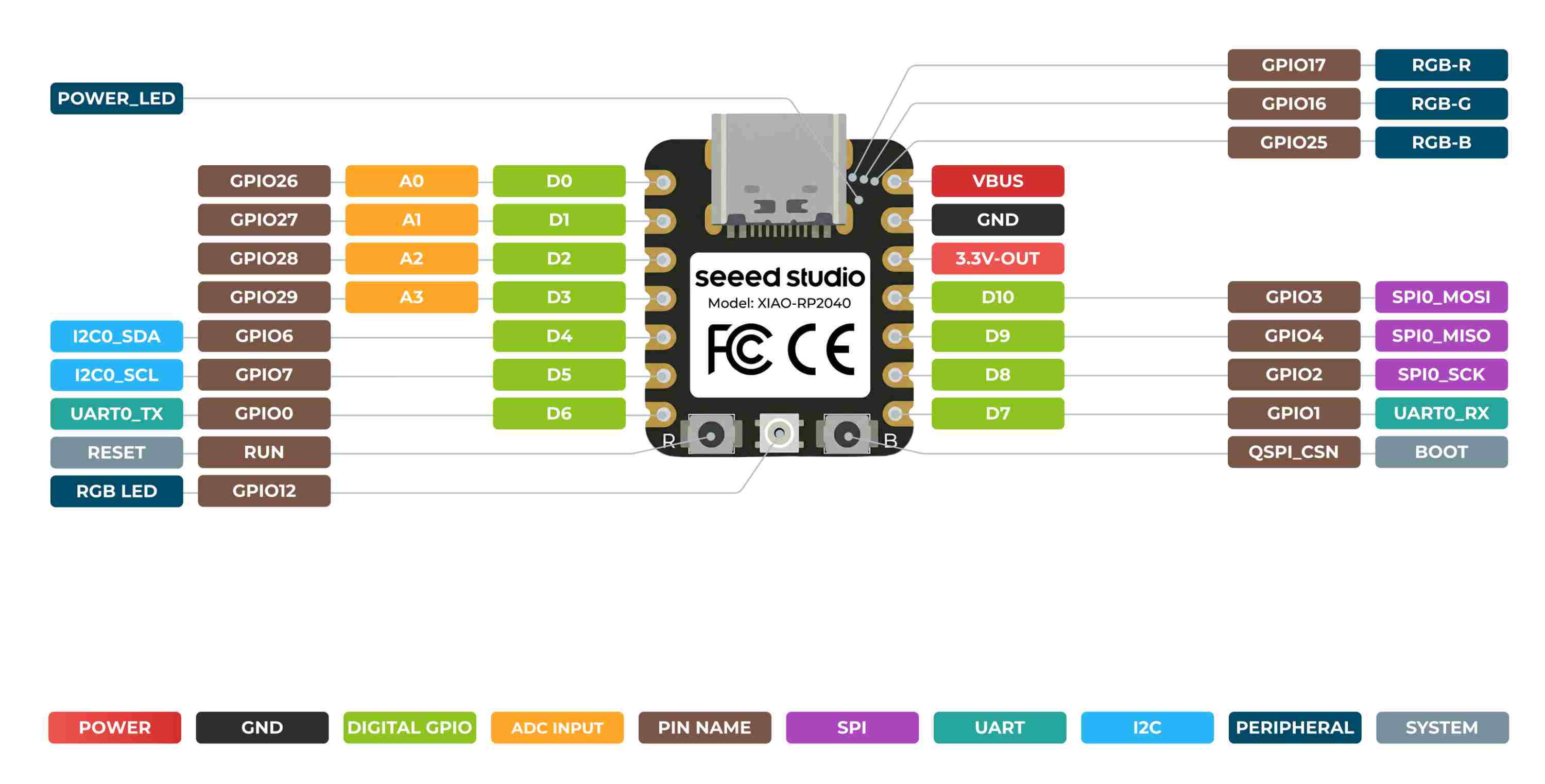
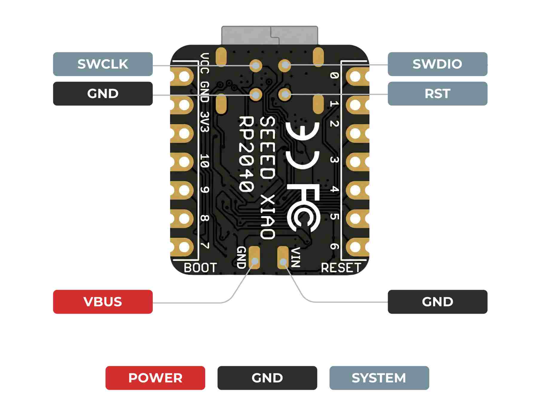
When Seeed Studio built the XIAO RP2040, they took that chip and packaged it into a tiny board. In doing that, they connected certain chip pins to specific pins on the board. This is where the schematic comes in.
This tells us what type of pin each one is.
The GPIO pins are named from D0 to D10. These are digital GPIO pins, as this is the pin name we enter in the Arduino IDE.
Some of the GPIO pins are integrated with UART, I2C, SPI MOSI, and SPI MISO.
UART pins are used for communication.
I2C: SDA and SCL are usually used to connect to an RTC.
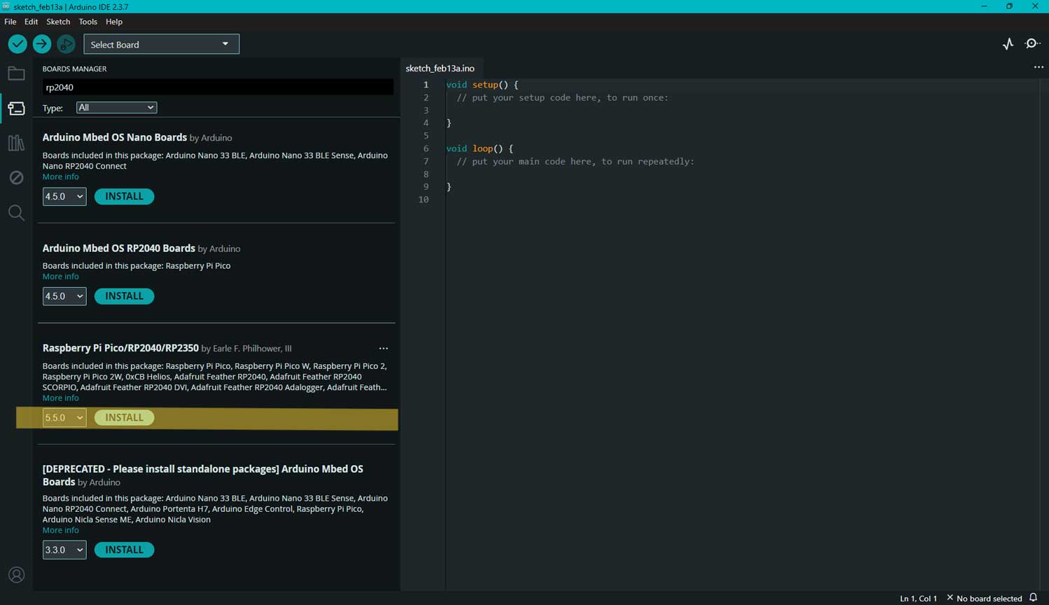
Selected the latest version of "Raspberry Pi Pico/RP2040/RP2350"
Installed the package successfully.
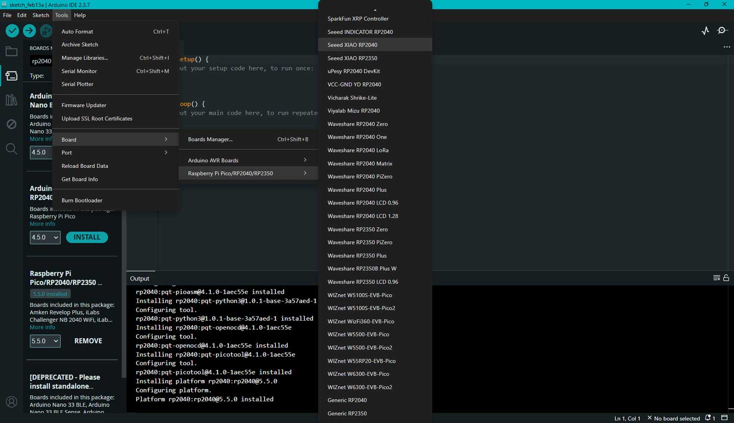
BOARD - After installing the board package, I navigated to Tools > Board, found "Seeed Studio XIAO RP2040,"
and selected it.
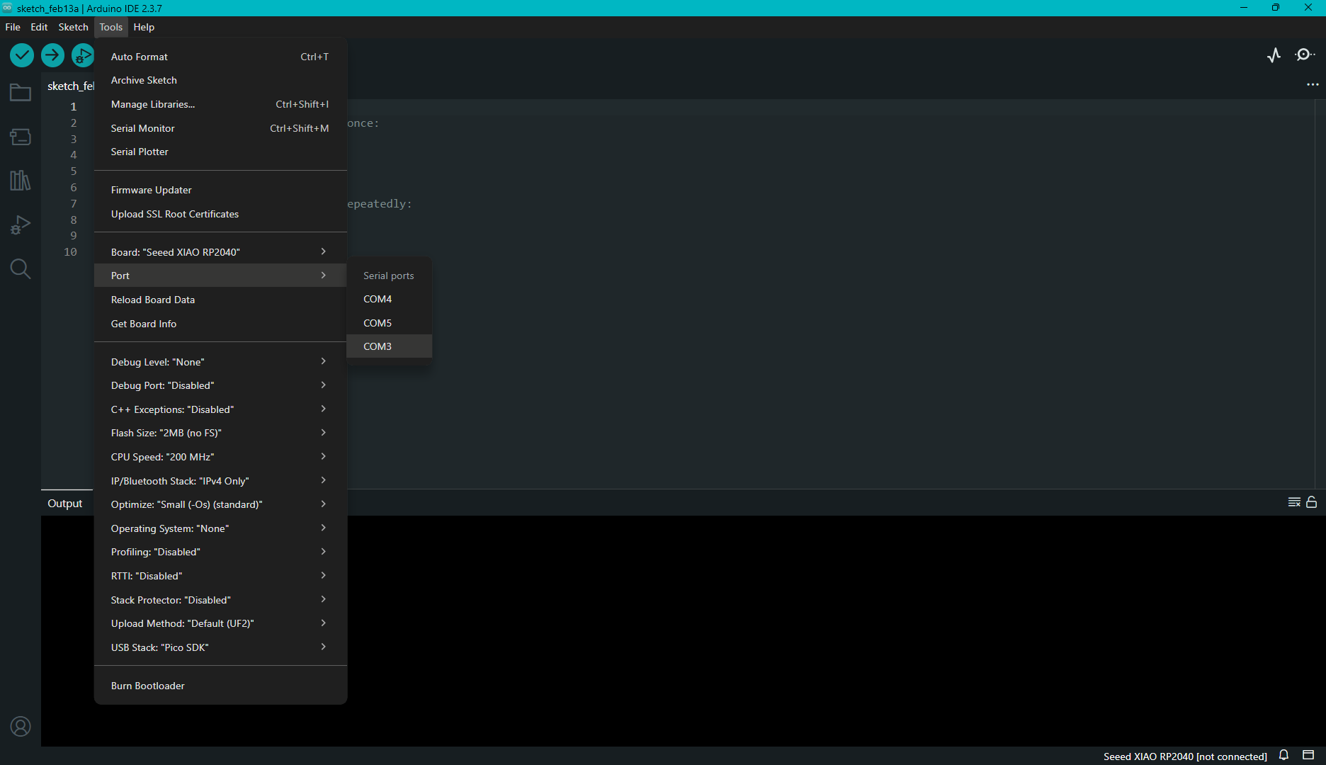
PORT - I navigated to Tools > Port and selected the serial port name of the connected Seeed Studio XIAO RP2040.
This was likely to be COM3 or higher. This is where we have connecetd our RP2040
Now I have finished setting up the Seeed Studio XIAO RP2040 for Arduino IDE.
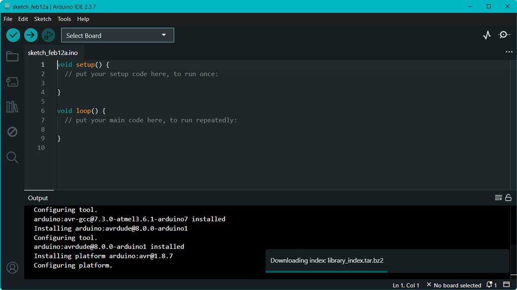
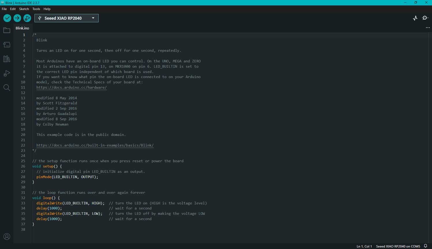
Arduino IDE 2.3.x Interface Overview
Navigating the Arduino IDE Interface
When I opened the IDE to program my Seeed Studio XIAO RP2040,
I focused on two main areas to manage my code and monitor the hardware status.
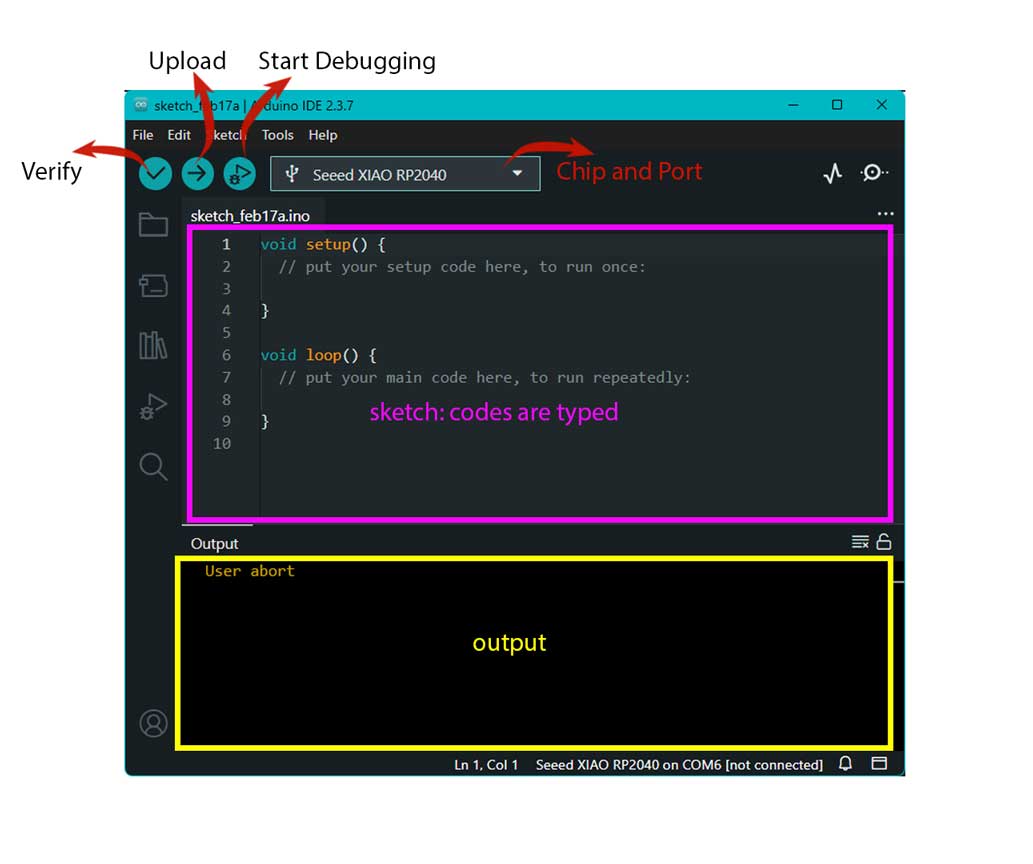
The Editor & Toolbar
This served as my primary workspace for writing instructions for the board.
Verify: I used this to compile my code and catch any syntax errors before attempting to send it to the board.
Upload: Once the code was ready, I clicked this to send the script directly to the XIAO RP2040.
Board Selector: I made sure this was set to "Seeed Studio XIAO RP2040" so the IDE knew exactly which hardware it was talking to.
The Sketch Structure:
void setup: I placed the code here that only needed to run once, such as defining my pin modes for the LEDs.
void loop: This is where I wrote the main logic that repeats indefinitely, allowing me to create continuous blinking patterns.
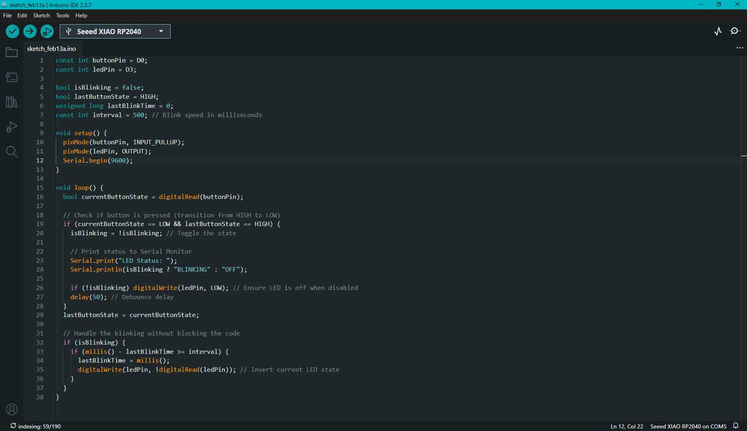
Understanding Syntax Highlighting in Arduino IDE
While writing the Blink program in Arduino IDE 2.x, I observed different colors in the code editor.
These colors help me understand the structure and function of the program.
Orange: I see orange used for important Arduino functions such as
setup(), loop(), digitalWrite(),
delay(), and pinMode().
These are built-in functions that control the behavior of the microcontroller.
Cyan (Light Blue): Cyan represents keywords and predefined constants like
void, HIGH, LOW, and OUTPUT.
These define data types, logic levels, and configuration settings.
Grey: Grey indicates comments.
Comments are written using // or /* */.
They are ignored by the compiler and are used to explain the code.
The color coding improves readability and helps me quickly understand different parts of the program.
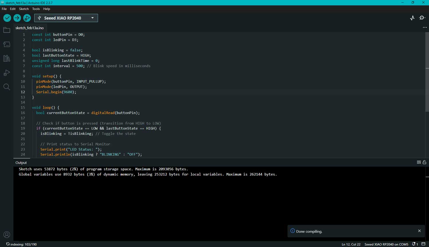
The Output Console
I relied on the bottom section of the interface to get real-time feedback on the "health" of my project.
Current Status: In my case, the console showed "User abort," which indicated that
I had stopped an upload or compilation process midway.
Error Tracking: This is where the IDE flagged typos—highlighting them in red text so I could quickly
fix them.
Blink Test – Seeed Studio XIAO RP2040
Summary
I tested the Seeed Studio XIAO RP2040 board using the Blink example in Arduino IDE
to confirm proper installation and functionality. After selecting the correct board
and port, I uploaded the example code. The onboard LED blinking at a fixed interval
confirmed successful setup and upload.
1. Basic Requirements
Hardware
Seeed Studio XIAO RP2040 board
USB Type-C data cable
Computer (Windows / Mac / Linux)
Software
Arduino IDE installed
RP2040 board package installed
USB drivers (if required)
2. Board and Port Selection
Select Board:
Tools → Board → Seeed Studio XIAO RP2040
Select Port:
Tools → Port → Select the appropriate COM port
(Port appears only after connecting the board)
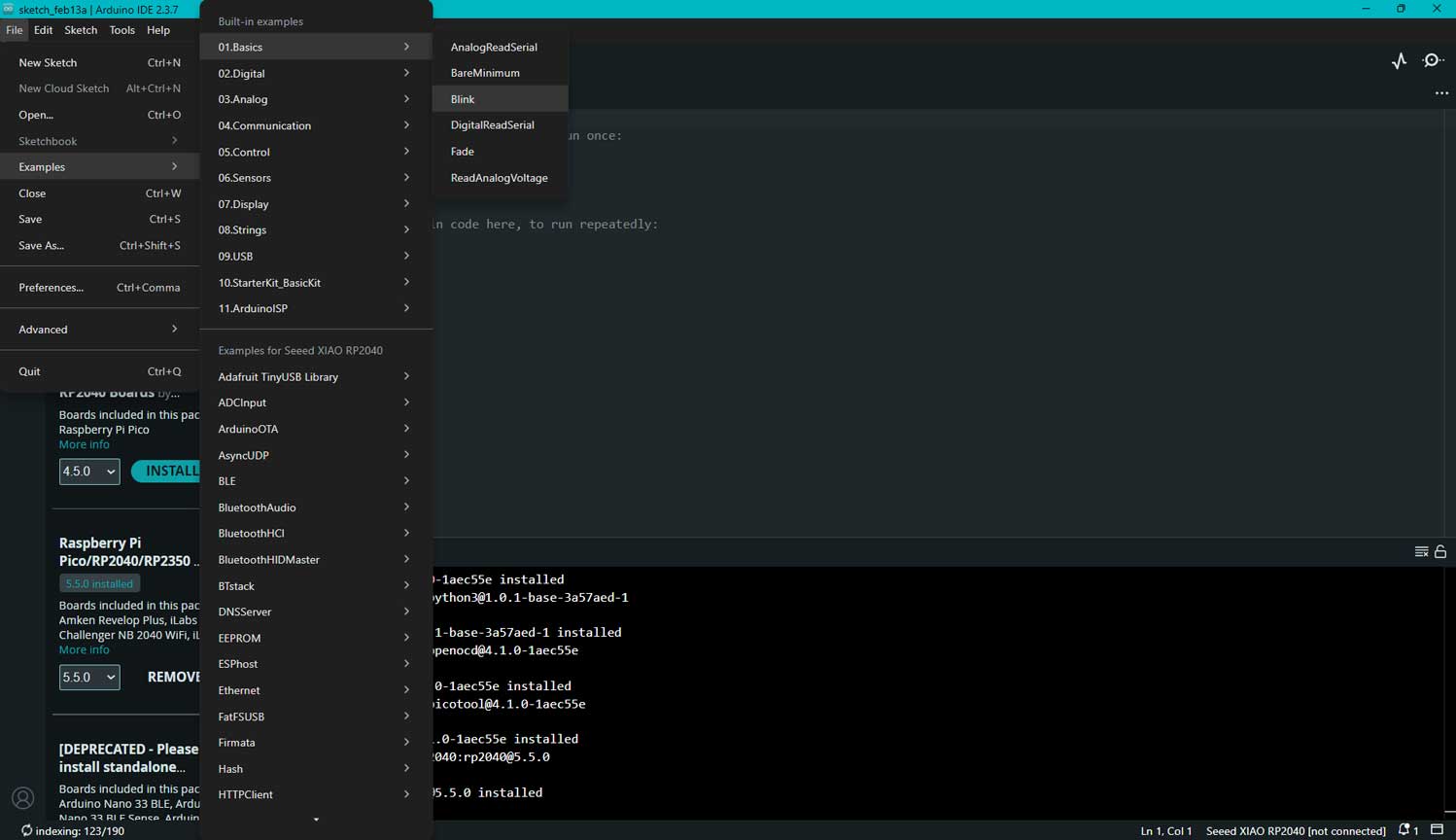
3. Blink Example
Open:
File → Examples → 01.Basics → Blink
Code explained
Source + wiki.seeedstudio.com - Created to show : GPIO 25 pin - User-controlled blue RGB LED pin in XIAO RP2040
LED_BUILTIN – The LED on the board. LED_BUILTIN is used in the code for Arduino to understand which onboard LED should be controlled. The developer board connected is selected from the board list. The board definition files specify which GPIO pin the onboard LED is connected to. During compilation, LED_BUILTIN is replaced with the GPIO number defined for that board. For the Seeed XIAO RP2040, this is GPIO 25. This GPIO number is what the microcontroller understands. Therefore, when the code writes to GPIO 25, the onboard LED connected to GPIO 25 blinks.
pinMode(LED_BUILTIN, OUTPUT); – Sets the LED's pin as OUTPUT
digitalWrite() – Inside this we define what action it has to do
digitalWrite(LED_BUILTIN, HIGH); – This defines that the LED is HIGH or ON
delay(1000) – 1000 milliseconds, that is a 1 second delay in performing the next action
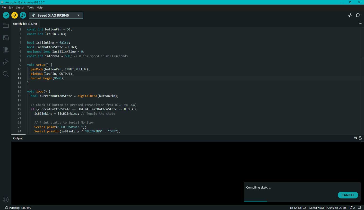
4. Upload Process
Connected the board via USB.
Clicked Verify (✔).
Clicked Upload (→).
Waited for the “Done Uploading” message.
If upload failed:
Pressed and held the BOOT button while connecting.
Rechecked board selection.
Rechecked port selection.
5. Expected Output
The onboard LED blinked continuously:
1 second ON
1 second OFF
I tested out a preset function in Arduino IDE. I remember being told that one need not always create code from scratch;
instead, I worked from an existing file to understand the logic and later modified it to suit my specific hardware needs.
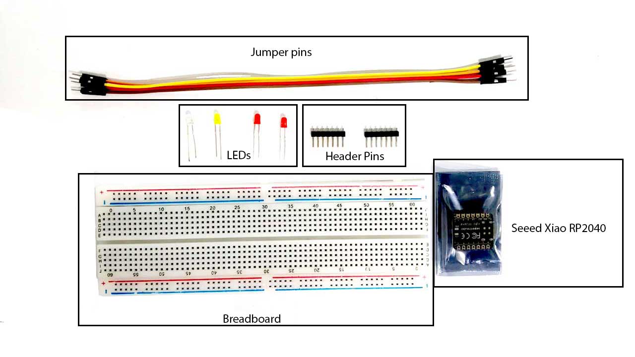
Components Used
Breadboard
Used for temporary circuit prototyping
Center rows are internally connected in groups of five
Side rails distribute VCC (+) and GND (–)
Seeed Studio XIAO RP2040
Microcontroller based on the RP2040 chip
Operates at 3.3V logic
Programmed using Arduino IDE and MicroPython
Controls LEDs and reads button input
LEDs (Red, Yellow, White)
Visual output components
Long leg – Anode (+)
Short leg – Cathode (–)
Requires a current-limiting resistor
Brightness: White appears brightest (~3V), Yellow medium, Red slightly dimmer (~2V)
Header Pins
Soldered to the board for stable breadboard connections
Jumper Wires
Used to connect GPIO pins, power, and ground
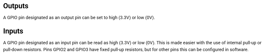
Working Principle
HIGH signal → LED ON
LOW signal → LED OFF
Button-Controlled LED Blinking using Seeed XIAO RP2040
In this experiment, I used the Seeed XIAO RP2040 board
and programmed it using the Arduino IDE software.
Software Setup
I installed the Arduino IDE and added the Seeed XIAO RP2040 board package.
After selecting the correct board and port, I uploaded the code to the microcontroller.
The button was configured using INPUT_PULLUP. Since the internal pull-up resistor was used:
HIGH → Button not pressed
LOW → Button pressed
Prompt:
I've an LED connected to D3, and button to D0, of a xiao rp2040. I want a program which allo me click the button to turn on blinking the led and turn off when I click again, then it should print the leds status on serial monitor. A SIMPLE CODE
const int buttonPin = D1; //button connected to
const int ledPin = D3; //led connected to pin

bool isBlinking = false; //bool means 2 conditons
bool lastButtonState = HIGH; //the previous state of the button the button is always high
unsigned long lastBlinkTime = 0; //the last time led changed
const int interval = 500; // the blink speed is 500 milliseconds. That is 0.5 seconds.

void setup() {
  pinMode(buttonPin, INPUT_PULLUP); //button is input
  pinMode(ledPin, OUTPUT); //output is led
  Serial.begin(9600); //serial communication baud rate
}
//This is the condition. When the button is pressed it pulls the line low and then moves it high.

void loop() {
  bool currentButtonState = digitalRead(buttonPin); // current state of button

  // Checks if the button is pressed (transition from HIGH to LOW) c
  if (currentButtonState == LOW && lastButtonState == HIGH) { //in the void loop, "if" states the condition. If the button is pressed, pulling the line to low and then releasing it back to high, the LED will blink.
    isBlinking = !isBlinking; // the current state

    // Print status to Serial Monitor
    Serial.print("LED Status: "); //this would be common
    Serial.println(isBlinking ? "BLINKING" : "OFF"); // this chaages based on state

    if (!isBlinking) digitalWrite(ledPin, LOW); // Ensure LED is off when disabled
    delay(50); // Debounce delay
  }
  lastButtonState = currentButtonState; //

  // Handles the blinking without stopping rest of the programme
  if (isBlinking) {
    if (millis() - lastBlinkTime >= interval) { //checks if enough time has passed since last blink
      lastBlinkTime = millis();
      digitalWrite(ledPin, !digitalRead(ledPin)); // Inverts the  current LED state
    }
  }
}
The pins are defined. bool lastButtonState = HIGH; when the button is pressed it is understood as a high state. const int interval = 500; the blink speed is 500 milliseconds. That is 0.5 seconds.
This is the condition. When the button is pressed it pulls the line low and then moves it high. The resistor connected to it always keeps the button in high.
The LED is the output given, and the serial print is 9600. This is the speed at which the Arduino talks to the computer via the Serial Monitor.
if (currentButtonState == LOW && lastButtonState == HIGH) { in the void loop, "if" states the condition. If the button is pressed, pulling the line to low and then releasing it back to high, the LED will blink. delay(50); // Debounce delay the Arduino takes 50 milliseconds to register an action. Meaning if the button, when pressed once, would be registered as being pressed 10 times by the Arduino as the time is in milliseconds. To avoid this, Arduino considers the 50 ms to register that as one touch or press.
Each time I pressed the button, the LED switched between blinking and off.
The current status (BLINKING or OFF) was displayed in the Serial Monitor
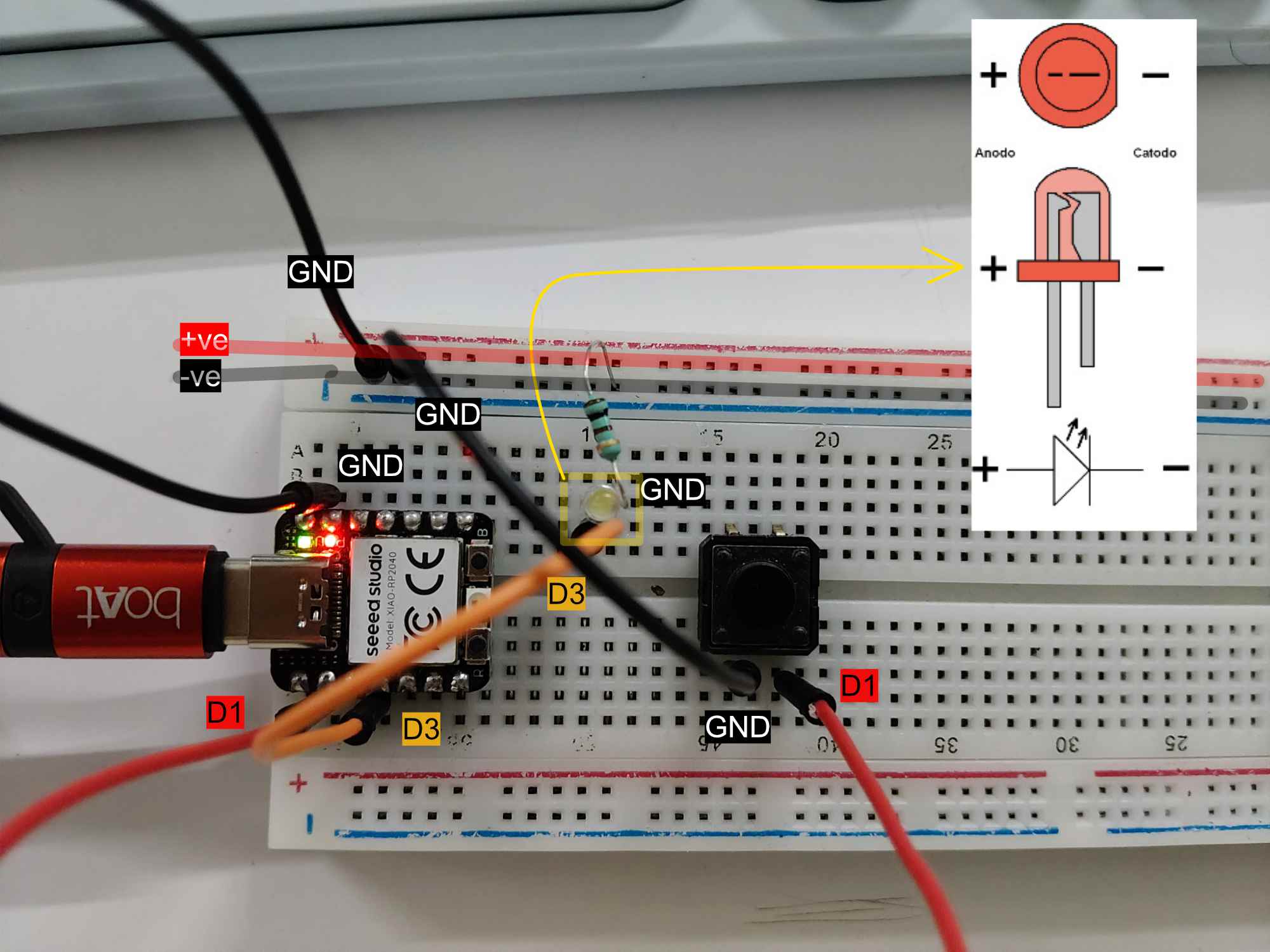
for confirmation.
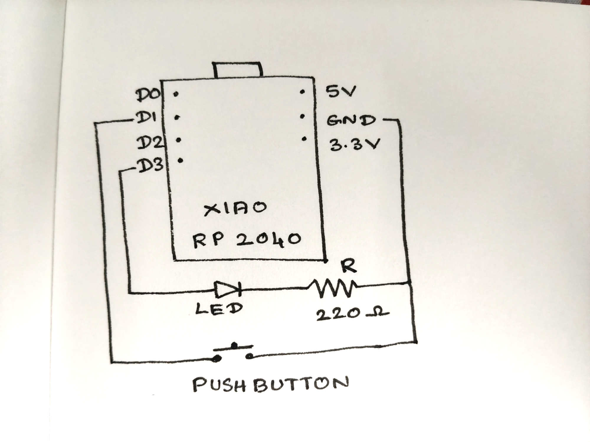
I had to do the serial monitor communication later, so at that time this was how I made the connections. The LED has polarity, which can be identified by the leg length. The longer leg is the anode or positive side. On the board, I connected the digital pin D3 to the positive side of the breadboard. One end of the resistor was connected to the power side, and then to GND through the shorter leg of the LED.
Hand drawn circuit diagram .
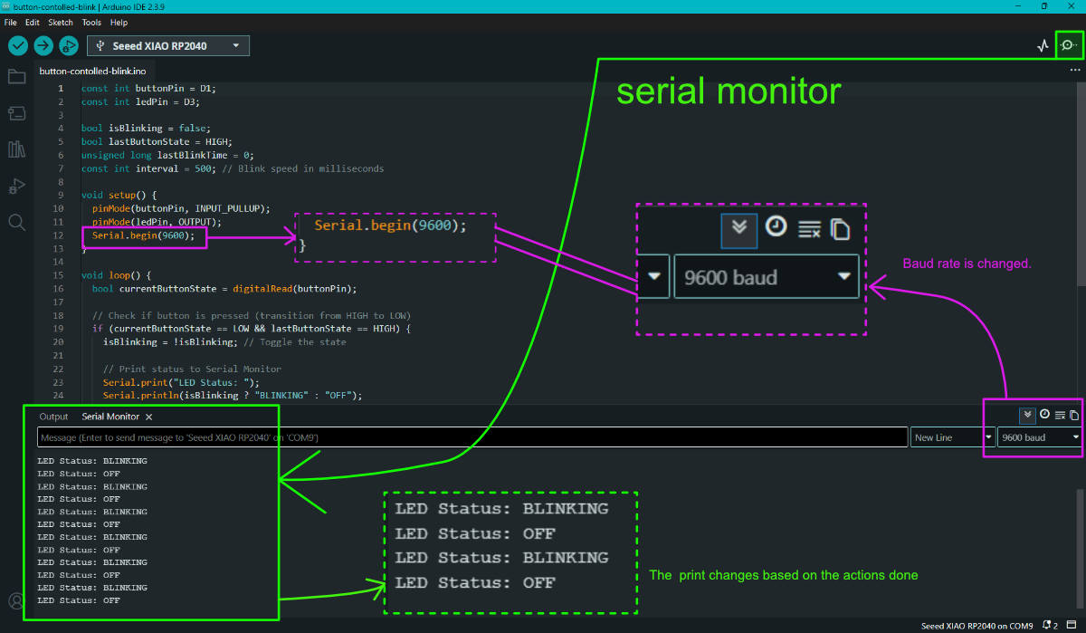
Serial Monitor
Shows the serial monitor output.
The serial monitor displays the data sent from the board to the Arduino to help us understand an action's state. It prints an output that the programmer sends. Here it is the XIAO RP2040. Here, print was about the state of the LED, whether it was blinking or not.
There is an icon in the top right corner. It opens the serial monitor along with the output box. Baud rateis the communication speed between the board and Arduino. That is the rate at which the board talks to the serial monitor in Arduino. The baud rate has to be adjusted according to the one in the code. If the baud rate is different, the serial monitor might not print the output in a readable format.
Using MicroPython with Seeed XIAO RP2040 (Using Thonny)
Introduction
After working with Arduino IDE, I explored programming the Seeed XIAO RP2040 using MicroPython.
Instead of writing C/C++ code like in Arduino, I used Python language to control the board.
For this, I installed Thonny IDE and prepared the board for MicroPython programming.
Step 1: I downloaded and installed the latest version of Thonny IDE according to my operating system (Windows).
Step 2: After installation, I opened Thonny IDE.
Step 3: I will configure the interpreter in the next step after installing the MicroPython firmware.
3 Opening Thonny and Accessing Settings
Once the installation was complete, I launched Thonny.
Then I went to:
Tools → Options
This opened the Thonny settings window.
4 Selecting the Interpreter
Inside the Options window, I selected the Interpreter tab.
Here, I chose:
Interpreter: MicroPython (Raspberry Pi Pico)
Port: Try to detect port automatically
This allows Thonny to automatically identify my connected board.
5 Connecting the Seeed Studio XIAO RP2040
Next, I connected my Seeed Studio XIAO RP2040 to the PC.
To install MicroPython firmware:
I pressed and held the BOOT button.
While holding it, I connected the board to my computer using a Type-C cable.
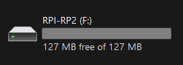
A new drive named RPI-RP2 appeared on my computer.
This confirmed that the board entered bootloader mode.
6 Installing MicroPython Firmware
Back in Thonny, I clicked:
Install or update MicroPython
Thonny automatically detected the board and showed:
Target Volume: RPI-RP2
MicroPython family: RP2
Variant: Raspberry Pi Pico / Pico H
Version: (I left the default version selected)
I then clicked Install.
After a few seconds, the installation completed and showed Done.
Once the firmware installation finished, the device was ready to use with MicroPython in Thonny.
Blink Test with Seeed XIAO RP2040 (Using Thonny)
Followed the "Seeed Studio XIAO RP2040 with MicroPython" doumentation in Wiki.seeedstudio.com
Connected the XIAO RP2040 board to my computer and opened Thonny IDE.
Selected the MicroPython (Raspberry Pi RP2040) interpreter to run the code on the board.
from machine import Pin, Timer #imports the needed tools to control pin and run timer

led = Pin(25, Pin.OUT) #pin 25 is an output
Counter = 0 #  this starts a counter at 0 to keep track of time by counting from 0, 1, 2...
Fun_Num = 0 #this prints on the serial monitor.

def fun(tim): #this is a name for a function
    global Counter #a more like a paramteric name in hich we can collcivley change the value
    Counter = Counter + 1 #counter increased by 1 as timer runs
    print(Counter)
    led.value(Counter%2) #this action turns the LED on when the counter is an odd number. When the counter is even, it turns it off.

tim = Timer(-1) #creates sotware timer
tim.init( #this automates the function to blink the LED and run the counter.
    period=1000, #timer runs for 1000miliseonds
    mode=Timer.PERIODIC, #to repeat
    callback=fun # runs the function called FUN
)
Upload the code by clicking the "Run current script" button.
Code explained
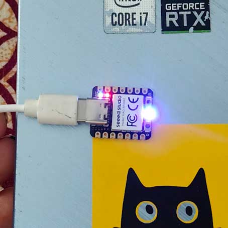
What happens is that there are USER LEDs on the XIAO, and it lights up and blinks.
led = Pin(25, Pin.OUT) I used pin 25 specifically because the seeed xiao rp2040 schematic shows gpio 25 is hardwired to the onboard user LED. so no external wiring was needed, the board already has it connected internally. Counter = 0 this starts a counter at 0 to keep track of time by counting from 0, 1, 2...
print(Counter) this prints on the serial monitor.
led.value(Counter%2) this action turns the LED on when the counter is an odd number. When the counter is even, it turns it off.
tim.init(period=1000, mode=Timer.PERIODIC, callback=fun) this automates the function to blink the LED and run the counter.
Open the downloaded file in Thonny. Go to File > Save As. Save it to the Raspberry Pi Pico location in the pop up window. The file name has to be saved as ws2812.py because in the later code this is how we tag or use this file. If the file name is different, it will not work.
git
Connected the XIAO RP2040 board to my computer and opened Thonny IDE.
Selected the MicroPython (Raspberry Pi RP2040) interpreter to run the code on the board.
Copied the sample code from the guide into Thonny’s editor to control the onboard RGB LED.
from ws2812 import WS2812 #imports these to control the neopixel
import utime #imports time functions
import machine #to contorl the machine
power = machine.Pin(11,machine.Pin.OUT) #defines pin11 as machine adn output
power.value(1) #1 means power on
BLACK = (0, 0, 0) #the rgb color codes
RED = (255, 0, 0) #the rgb color codes
YELLOW = (255, 150, 0)#the rgb color codes
GREEN = (0, 255, 0)#the rgb color codes
CYAN = (0, 255, 255)#the rgb color codes
BLUE = (0, 0, 255)#the rgb color codes
PURPLE = (180, 0, 255)#the rgb color codes
WHITE = (255, 255, 255)#the rgb color codes
COLORS = (BLACK, RED, YELLOW, GREEN, CYAN, BLUE, PURPLE, WHITE) # to collectively address them all

led = WS2812(12,1)#WS2812(pin_num, power on)

while True: #if it statisfies the below condition
    print("Beautiful color") #the serial output
    for color in COLORS: #changes color one by one as in the group
        led.pixels_fill(color)  #to light the led with color
        led.pixels_show() #led gets the data of the color to be used
        utime.sleep(0.2) #the delay in chnaging from one duration to another.
Code explained
from ws2812 import WS2812
import utime
import machine
These are the libraries and modules included in the file.
A NeoPixel RGB LED connected to GPIO11 (NEOPIXEL_POWER) and GPIO12 (PIN_NEOPIXEL). REFERNCE
    power = machine.Pin(11, machine.Pin.OUT)
    power.value(1)
The XIAO RP2040 has a neopixel (RGB LED) already soldered onto the board. To make it work, two things need to happen pin 11 controls the power going to the neopixel. Once the power is on, pin 12 is what tells the neopixel what color to show - it is the data line.
BLACK = (0, 0, 0)
RED = (255, 0, 0)
YELLOW = (255, 150, 0)
GREEN = (0, 255, 0)
CYAN = (0, 255, 255)
BLUE = (0, 0, 255)
PURPLE = (180, 0, 255)
WHITE = (255, 255, 255)
COLORS = (BLACK, RED, YELLOW, GREEN, CYAN, BLUE, PURPLE, WHITE)
The colors that the NeoPixel changes into are listed here along with their RGB color codes. These colors are grouped under the name "COLORS", so it is easy to call, tag, or use the group. led = WS2812(12,1) # WS2812(pin_num, led_count)
This tells us that pin 12 is connected to a WS2812 NeoPixel. while True: The "while True" loop is similar to the void loop() in the Arduino IDE. print("Beautiful color") Prints the text in the serial monitor. for color in COLORS: The COLORS group is referenced here. led.pixels_fill(color) Sends the color data. led.pixels_show() The LED receives the data and changes color. utime.sleep(0.2) Waits for 0.2 seconds. Here, the value is calculated in seconds. This is the delay between changing from one color to another.
Checked that the LED pins and GPIO settings in the code matched the board configuration.
Saved the script directly to the XIAO RP2040 for execution.
Ran the code and observed the RGB LED cycling through colors and flashing as described.
The message "Beautiful Color" appeared in the Thonny Shell, confirming the test run was successful.
Using Thonny to try to fade and change color
In my project, I am simulating the sun moving along a path with its colors
changing throughout the day. I am experimenting with the Seeed Studio XIAO RP2040 to
control LEDs that fade smoothly between colors, mimicking natural sunlight transitions from
dawn to noon to dusk. Using MicroPython, I adjust RGB values and brightness to create a
realistic effect of the sun’s journey, producing a dynamic visual representation of daylight
progression.
    Write a MicroPython program for the Seeed Studio XIAO RP2040 that
    smoothly fades the onboard NeoPixel from red to a warm yellow over 30 seconds.
    The program should use the machine, neopixel, and utime libraries. First, turn
    on the RGB power by setting Pin 11 as an output and driving it HIGH. Then control
    one NeoPixel connected to Pin 12. Define the starting color as (255, 0, 0) (red)
    and the ending color as (255, 180, 50) (warm yellow). The fade  should happen
    gradually over 30 seconds using 100 steps for smoothness. Use linear
    interpolation inside a loop to calculate intermediate RGB values, update the
    LED color at each step, and add the appropriate delay using utime.sleep().
    After the fade is complete, print "Fade complete". The code should be clean,
    properly commented, and fully runnable on the board.
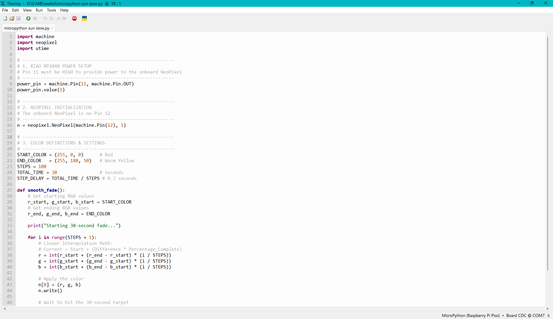
import machine #to contorl the machine imports this
import neopixel #to contorl the neopixel imports this
import utime #imports time functions

# ---------------------------------------------------------
# 1. XIAO RP2040 POWER SETUP
# Pin 11 must be HIGH to provide power to the onboard NeoPixel
# ---------------------------------------------------------
power_pin = machine.Pin(11, machine.Pin.OUT) # defines machine is conencted to pin11, and output
power_pin.value(1) #power ON

# ---------------------------------------------------------
# 2. NEOPIXEL INITIALIZATION
# The onboard NeoPixel is on Pin 12
# ---------------------------------------------------------
n = neopixel.NeoPixel(machine.Pin(12), 1) #neopixel's pin

# ---------------------------------------------------------
# 3. COLOR DEFINITIONS & SETTINGS
# ---------------------------------------------------------
START_COLOR = (255, 0, 0)      # Red #mentioned as START_COLOR so easy to addresss this as start
END_COLOR   = (255, 180, 50)   # Warm Yellow #mentioned as END_COLOR so easy to addresss this as end
STEPS = 100
TOTAL_TIME = 30                #the color change happens in 30 seconds
STEP_DELAY = TOTAL_TIME / STEPS # 0.3 seconds 30/100

def smooth_fade(): #names function
    # Get starting RGB values
    r_start, g_start, b_start = START_COLOR #states that  RGB lights by extracting the value from start_color
    # Get ending RGB values
    r_end, g_end, b_end = END_COLOR  #states that  RGB lights by extracting the value from end_color

    print("Starting 30-second fade...") #prints message to serial monitor

    for i in range(STEPS + 1): #loop
        # Linear Interpolation Math:
        # Current = Start + (Difference * Percentage_Complete)
        r = int(r_start + (r_end - r_start) * (i / STEPS)) #this is how the current red value is calculated
        g = int(g_start + (g_end - g_start) * (i / STEPS))#this is how the current green value is calculated
        b = int(b_start + (b_end - b_start) * (i / STEPS))#this is how the current blue value is calculated

        # order inwhich the color code is send
        n[0] = (r, g, b)
        n.write() #data sen to neo pixel

        # Wait to hit the 30-second target
        utime.sleep(STEP_DELAY)

    print("Fade complete") #end serial moniot reading

# Run the program
smooth_fade()
Code explained
power_pin = machine.Pin(11, machine.Pin.OUT) Define pin 11. n = neopixel.NeoPixel(machine.Pin(12), 1) Pin 12 is the NeoPixel.
This denotes the RGB color code of the color the NeoPixel light is going to be lit as. The 2 colors it mentions are start and end, and those RGB color values. The color change happens in 30 seconds (unlike the milliseconds mentioned in Arduino). The number of steps is 100, so the delay in color change is 30 seconds / steps. Therefore, the color change happens from red to warm yellow gradually rather than a quick change.
The red is denoted as the start color and the warm yellow as the end color, and this shows how the code uses it again. r_start, g_start, b_start = START_COLOR so in the values of RGB, it is written as start because the values of start are stated first. So any changes in the start value are automatically understood.
for i in range(STEPS + 1):
    # Linear Interpolation Math:
    # Current = Start + (Difference * Percentage_Complete)
    r = int(r_start + (r_end - r_start) * (i / STEPS))
    g = int(g_start + (g_end - g_start) * (i / STEPS))
    b = int(b_start + (b_end - b_start) * (i / STEPS))
For the color to change gradually, it moves in steps. The delay is so tiny that it looks like a smooth transition, so that transition is calculated by starting at the red color RGB value, and then adding the difference into the percentage completed.
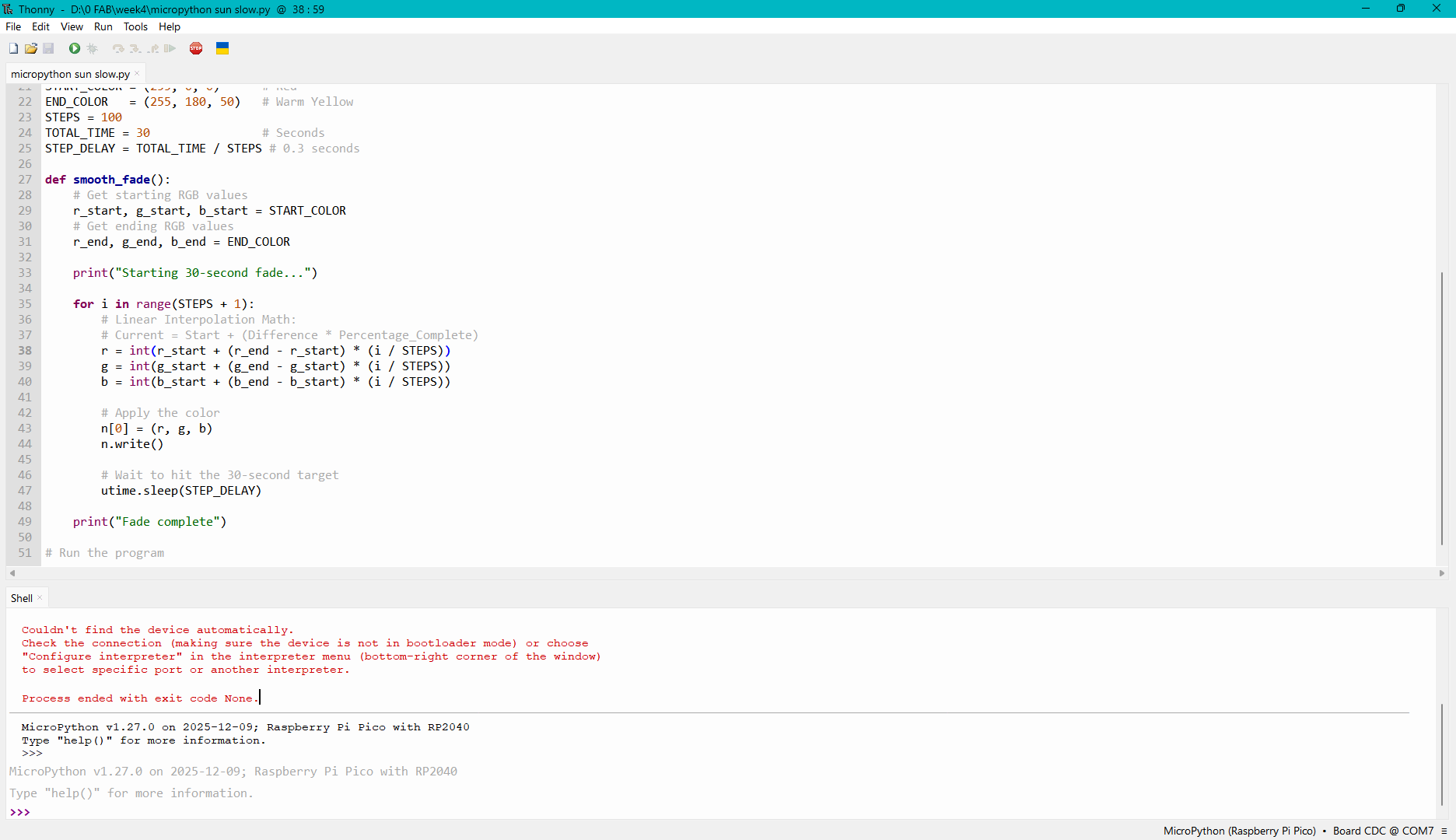
I pasted the given code into thonny.
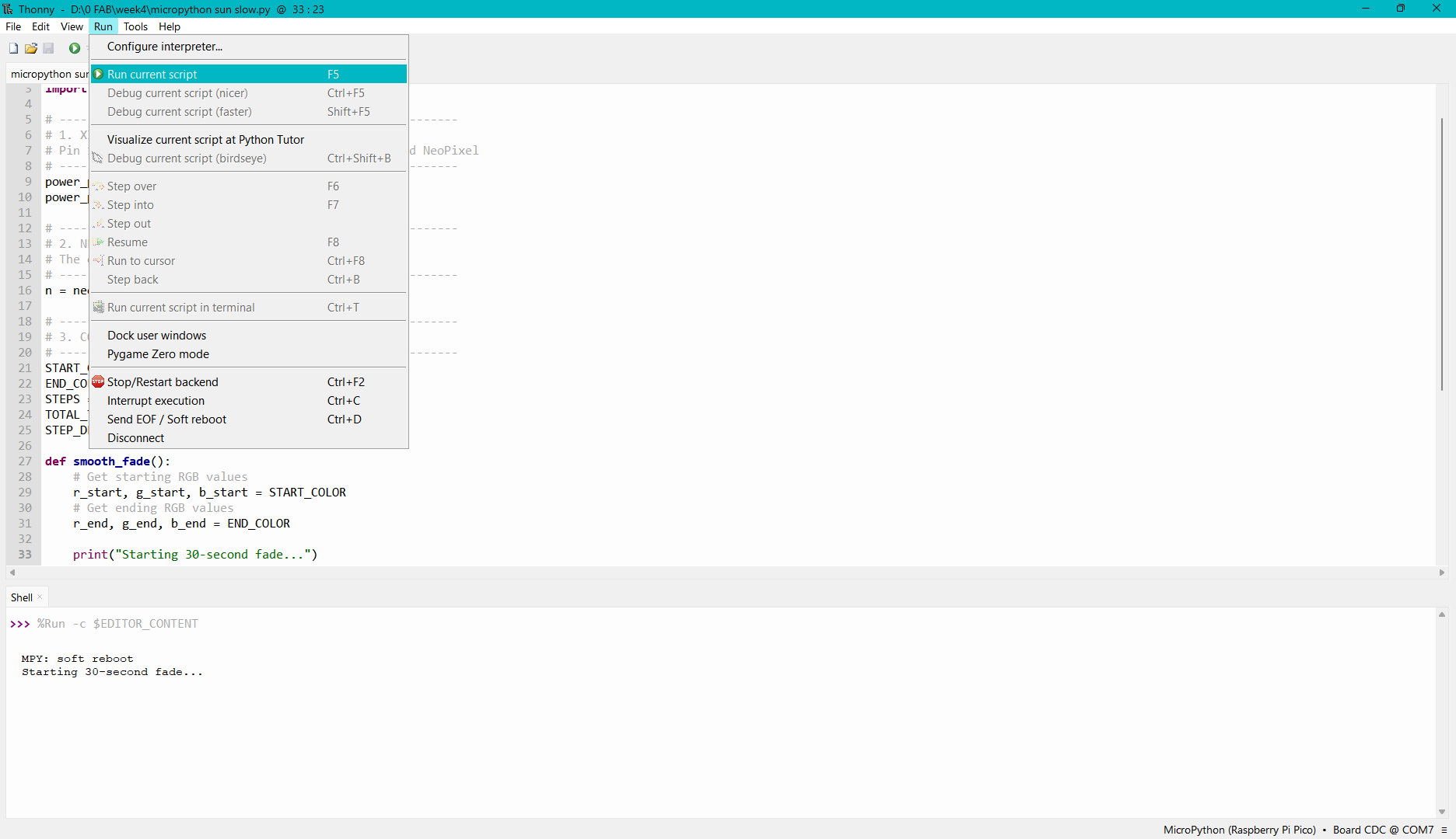
This step has to be down if the micro-contoller was unplugged "6 Installing MicroPython Firmware"
or else you will run into error like i did
Then run the code by pressing F5 or Run -> Run current script
In the above video I edited the time to 10 seconds

.jpg)
.jpg)
.jpg)
.jpg)
.jpg)

.jpg)
.jpg)