Week 11 – Networking and Communications
This week is about networking and communication between microcontroller nodes.
The objective is to learn wire and wireless communication.
AI prompt ChatGPT: "Can you give me my avatar an animated landscape image (I don't want realistic image)- where in I am in my week 11 of fab academy - "networking and communication" and I am trying I2C protocol, Bluetooth and Meshtastic LoRA communication. PLease use the attached images as reference and make avatar."
Assignment Overview
- Send a message between two projects and document your work to the group work page and reflect on your individual page what you learned
- Design, build, and connect wired or wireless node(s) with network or bus addresses and local input &/or output device(s)
| Day | Activity | Status |
|---|---|---|
| Thursday | Week Planning 📅, LAB Activity 📐 and Documentation 📝 | Completed |
| Class - Wire and Wireless Communications | Completed | |
| Friday | LAB Activity 🛠 - Charlieplexing (ATTiny 1624) Debugging and Power-up | completed |
| Saturday | LAB Activity 🛠 - I2C communication between XIAO ESP32C6 and Charlieplexing (ATTiny 1624) | Completed |
| Sunday | Documentation 📝 | Completed |
| Monday | LAB Activity 🛠 - I2C hub design and milling | Completed |
| Reflection and Learnings 💡 | Completed | |
| Complete Documentation - Regional Review 📝 | Completed | |
| Tuesday | Regional Review 👨🏫💬 | Completed |
| Lab Activity 🛠 - Design 📐 - LoRA with Meshtastic | Completed | |
| Wednesday | Go the Extra Mile - On Final Project⚙️ | Completed |
| NuEval - Final Documentation 🏁 | Completed |
Individual Assignment
Connect multiple nodes, there needs to be an address, can be a network address or bus address, connect nodes, connect two processor I make, or connect to phone, there has to be an address that I need ot talk to it, and local input going and coming into the network and output.
I2C Communication
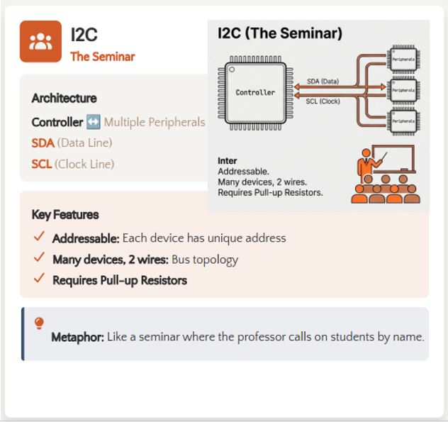
I²C (Inter-Integrated Circuit) is a synchronous serial communication protocol developed by Philips (now NXP). It allows multiple integrated circuits (ICs) to communicate with each other using only two wires.
It is one of the most widely used communication protocols in embedded systems because it requires very few connections while allowing multiple devices to share the same communication bus.
Common devices that use I²C include:
- Temperature Sensors – Measure ambient or object temperature.
- Heart Rate Sensors (MAX30102) – Measure heart rate and blood oxygen levels.
- OLED Displays – Display text, graphics, and sensor data.
- EEPROM Memory – Store configuration settings and data permanently.
- IMU Sensors – Measure acceleration, rotation, and orientation.
- Microcontrollers – Exchange data with other microcontrollers or peripheral devices.
Two Communication Lines
I²C communication requires only two wires to transfer data between the Main device and one or more Subordinate devices.
SDA (Serial Data)
- Transfers the actual data between devices.
- Supports bidirectional communication, allowing data to be sent and received over the same wire.
- Used by both the Main device and the Subordinate devices during communication.
SCL (Serial Clock)
- Provides the clock signal used to synchronize communication.
- The Main device generates the clock signal.
- Each bit transferred on the SDA line is synchronized with the SCL signal.
- All devices on the I²C bus use this clock for timing.
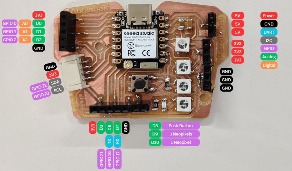
Microcontroller Board
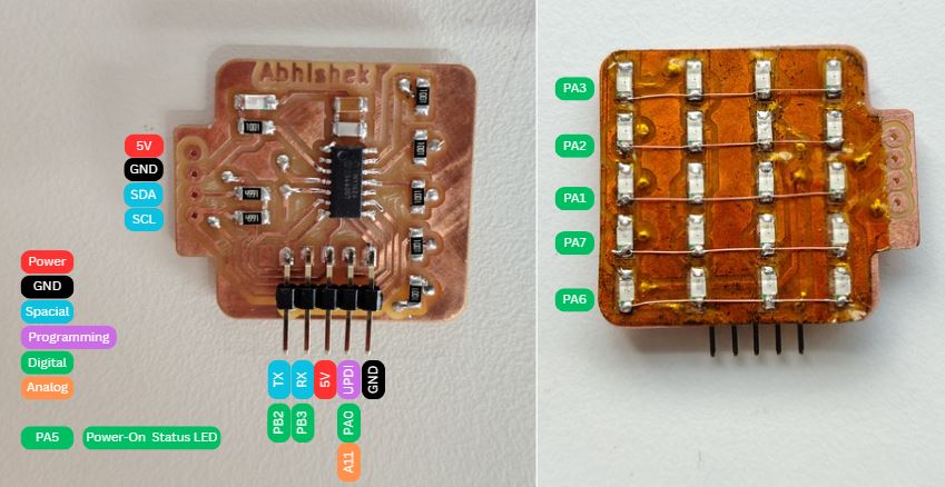
I decided to use my microcontroller board from my production week 8 and charliplexing board from output week 10 for wired communicate assignment. While designing my week 8 electronic production I added totaL I2C communication JST connector to interface other modules. And while designing charlieplexing board week 10 output devices I keep I2C for communication.
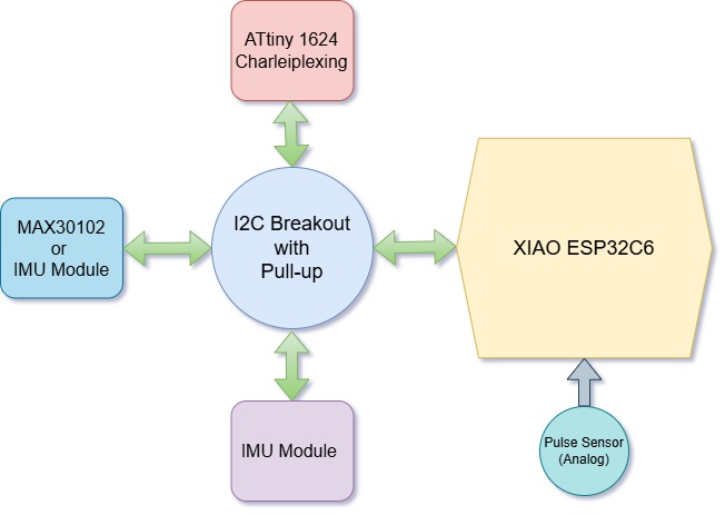
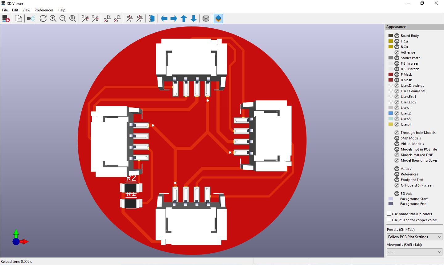
I2C Communication Hub
I used I2C communication between XIAO ESP32C6 and ATtiny 1426 microcontroller, I made I2C Hub because I need to connect multiple I2C sensor module and charliplexing which also work on I2C communication, thus I designed and milled I2C hub so that I can connect other sensors such as GY-BMI160 6DOF and MAX30102 in future and test it out.
For this assignment propose, I have connected a pulse sensors as local input and charlieplexing as output device. The pulse sensor is an analog sensor and which is connected to XIAO ESP32C6 and ATtiny 1426 is driving charlieplexing LEDs in Multiplexing operation.
Pull-Up Resistors in I²C
Unlike UART or SPI, devices on an I²C bus never drive the communication lines HIGH. Instead, they use an open-drain (open-collector) output, which means a device can only:
- Pull the communication line LOW.
- Release the communication line.
When no device is pulling the line LOW, an external pull-up resistor automatically pulls the line HIGH. This allows multiple devices to safely share the same SDA and SCL lines without electrical conflicts.
Typical Pull-Up Resistor Values
- 4.7 kΩ – Most commonly used for general-purpose I²C communication.
- 2.2 kΩ – Suitable for higher-speed I²C communication or buses with greater capacitance.
- 10 kΩ – Commonly used for short communication buses and low-speed applications.
Without pull-up resistors, the SDA and SCL lines would remain floating when released, making reliable communication impossible.
Note: I decided to add pull-up resisters in the I2C-Hub, so that all my future I2C breakout boards can be made without pull-up resistors and confusion of multiple pull-up resistors can be avoided.
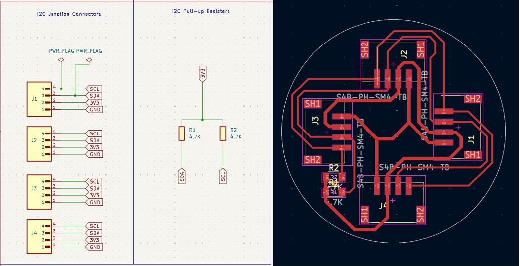
What Went Wrong - I2C Hub / Junction
I reversed / mirrored the I2C pin-out in the schematics, which resulted in wiring mismatch using standard I2C female-to-female wire.
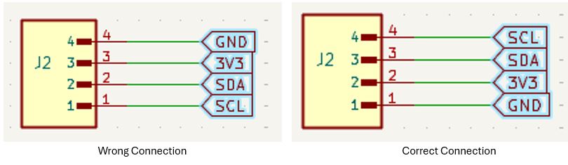
What I Learned - I2C Hub / Junction
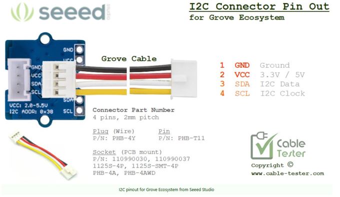
Always use standard wire sequence in the I2C connector, even though the connector in on top layer or on bottom layer always keep Pin 1 GND, Pin 2 - 3V3, Pin 3- SDA. and PIN 4 - SCL. Following this will always be correct because the connector can only get inserted in one direction, it has two grooves on the top of the connector which matches with the slots on the matting connector.
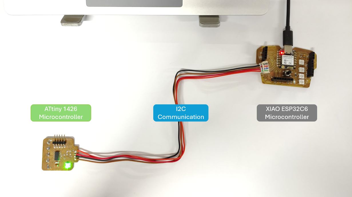
I2C communication between Two Microcontroller
Below I used two nodes one is XIAO ESP32C6 and one is ATtiny1624. I have Push button on XIAO ESP32C6 connected to D8 Pin which is active high and I have Status LED at pin PA5 on ATtiny1624 board. Thus the in this I2C communication when I press the button on XIAO ESP32C6 board the LED on the ATtiny1624 will blink.
ChatGPT AI prompt: "I want to do I2C communication between ATTiny1624 and XIAO ESP32C6. I have a button connected to D8 of XIAO ESP32C6 and LED connected to PA5 of ATTiny1624. So if I press push button it should turn on LED on ATtiny. Can you help me with both the program and also add comments in each line about its explanation."
// ESP32C6

#include

#define SUB_ADDR  0x08   // Address of ATtiny (must match slave)
#define BUTTON_PIN  D8      // D8 pin where button is connected

void setup() {

  Serial.begin(115200);
  // Start serial monitor for debugging

  pinMode(BUTTON_PIN, INPUT);
  // Configure button pin as INPUT (NO internal pull-up/pull-down)
  // External 10k pull-down handles default LOW state
  // Default = LOW, pressed = HIGH

  Wire.begin(22, 23);
  // Initialize I2C (SDA=22, SCL=23)

  Serial.println("ESP32 Main Ready");
}

void loop() {

  int buttonState = digitalRead(BUTTON_PIN);
  // Read button state

  Wire.beginTransmission(SUB_ADDR);
  // Start communication with slave

  if (buttonState == HIGH) {
    // Button pressed

    Wire.write(1);
    // Send value '1' → turn LED ON

    Serial.println("Button Pressed → LED ON");
  }
  else {
    // Button released

    Wire.write(0);
    // Send value '0' → turn LED OFF

    Serial.println("Button Released → LED OFF");
  }

  Wire.endTransmission();
  // End I2C transmission

  delay(100);
  // Small delay to avoid flooding I2C bus
}
// ATtiny1624

#include

#define SUB_ADDR  0x08   // Must match Main
#define LED_PIN     PIN_PA5      // PA5

volatile uint8_t receivedData = 0;
// Store incoming data (volatile because used in interrupt)

void receiveEvent(int howMany) {
  // This function runs automatically when data is received

  if (Wire.available()) {
    receivedData = Wire.read();
    // Read incoming byte
  }
}

void setup() {

  pinMode(LED_PIN, OUTPUT);
  // Set LED pin as output

  Wire.begin(SUB_ADDR);
  // Initialize as I2C slave

  Wire.onReceive(receiveEvent);
  // Register function to run when data arrives
}

void loop() {

  if (receivedData == 1) {
    digitalWrite(LED_PIN, HIGH);
    // Turn LED ON
  }
  else {
    digitalWrite(LED_PIN, LOW);
    // Turn LED OFF
  }
}
How the communication / main and sub addressing works:
- Subordinate address in the firmware of main microcontroller and subordinate micro-controller must be same. Here it is 0X08.
- Wire.begin( ) initializes the I2C communication - this command shall be there in both firmware in void setup( ). Without this the I2C communication will not start.
- In main micro-controller, Button pin Pin D8 is initialized as input, and in subordinate micro-controller the PA5 is initialized as LED output.
- Once initialized, the main micro-controller firmware will start communication with subordinate by using command Wire.beginTransmission(SUB_ADDR).
- Once initialized, the subordinate micro-controller function Wire.onReceive(receiveEvent) will run automatically when data is received.
- When the Button Status changes the main micro-controller firmware sends "1" and the subordinate microcontroller turn-Ons the LED until the status goes "0".
I2C communication between Three Nodes
Now My Instructor Saheen asked me to add one more node and to the I2C communication. First, I added another XIAO ESP32C6 to as Subordinate and made three micro-controller network.
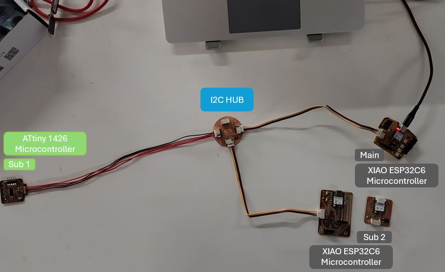
Network functioning is when I short-press (less than 0.5 sec) button on main micro-controller (XIAO ESP32C6) the status LED on Subordinate 1 (ATtiny1624) will flash twice and when I long-press (more than 0.5 sec) button on main microcontroller (XIAO ESP32C6) the status LED on Subordinate 2 (XIAO ESP32C6) will flash twice.
| Device | Controller | Button | Status LED | I2C Pins |
|---|---|---|---|---|
| Main | XIAO ESP32C6 | D8 (Active High) | D7 | SDA → D4 SCL → D5 |
| Subordinate 1 | ATtiny1624 | - | PA5 | SCL → PB0 SDA → PB1 |
| Subordinate 2 | XIAO ESP32C6 | D3 (Active Low) | D0 | SDA → D4 SCL → D5 |
ChatGPT AI prompt: "Please use Main/Subordinate terminology instead if Master/Slave terminology: I have three microcontrollers Boards: microcontroller 1 (Main): XIAO ESP32C6 which has Push button connected to D8 and it is Active High. It has LED connected on pin D8. microcontroller 2 (Subordinate 1) : ATtiny1426 which has LED connected on PA5. Microcontroller 3 (Subordinate 2) : ESP32C6 which has Push button connected to D3 it is Active low. and LED on D0. All three microcontrollers are connected via I2C communication and SDA and SCL lines are pulled-up to 3V3. I wan to do a basic communication between these three, when I short press push button on microcontroller 1 the LED of Subordinate 1 shall Blink twice. and when I long press push button on microcontroller 1 the LED of Subordinate 2 shall Blink twice."
#include   // Include I2C library
#define BUTTON_PIN D8   // Button connected to D8 (Active HIGH)
#define LED_PIN D7      // LED connected to D7
#define SUB1_ADDR 0x08  // I2C address of Subordinate 1 (ATtiny)
#define SUB2_ADDR 0x09  // I2C address of Subordinate 2 (ESP32)

unsigned long pressStart = 0;  // Stores time when button was pressed
bool prevState = LOW;  // Stores previous button state for edge detection


void setup() {

  pinMode(BUTTON_PIN, INPUT);  // Button uses external pull-down → no internal pull-up
  pinMode(LED_PIN, OUTPUT);  // LED pin set as output
  Wire.begin(22, 23);  // Initialize I2C as Main → SDA=22, SCL=23
  Serial.begin(115200);  // Serial monitor for debugging

}


void loop() {

  bool state = digitalRead(BUTTON_PIN);  // Read current button state
  // Detect button press (LOW → HIGH transition)

  if (state && !prevState) {
    pressStart = millis();
    // Record time when button was pressed
  }

  // Detect button release (HIGH → LOW transition)
  if (!state && prevState) {

    unsigned long duration = millis() - pressStart;  // Calculate how long button was held

    if (duration < 500) {
      // SHORT PRESS (<500ms)

      sendCommand(SUB1_ADDR, 1);  // Send command 1 to Subordinate 1
      Serial.println("SHORT PRESS → Sub1");
    }
    else {
      // LONG PRESS (>500ms)

      sendCommand(SUB2_ADDR, 2);  // Send command 2 to Subordinate 2
      Serial.println("LONG PRESS → Sub2");
    }
  }

  prevState = state;  // Update previous state for next loop iteration
}


// ── Function to send I2C command ─────────────
void sendCommand(uint8_t addr, uint8_t cmd) {

  Serial.print("Sending to: ");
  Serial.println(addr);
  Wire.beginTransmission(addr);  // Start communication with given address
  Wire.write(cmd);  // Send command byte
  Wire.endTransmission();  // End transmission → actually sends data
}
#include
#define LED_PIN PIN_PA5      // PA5 pin where LED is connected
#define I2C_ADDR 0x08  // I2C address for this device

volatile uint8_t command = 0;  // Stores received command (volatile → used in interrupt)


// ── I2C Receive Callback ───────────────────
void receiveEvent(int howMany) {

  if (Wire.available()) {
    command = Wire.read();  // Read incoming command byte
  }
}


void setup() {
  pinMode(LED_PIN, OUTPUT);  // Set LED pin as output
  Wire.begin(I2C_ADDR);  // Initialize as I2C Subordinate
  Wire.onReceive(receiveEvent);  // Register callback when data is received
}


void loop() {
  if (command == 1) {
    // If command is 1 → blink LED

    blinkTwice();  // Call blink function
    command = 0;   // Reset command after execution
  }
}


// ── Blink LED twice ────────────────────────
void blinkTwice() {
  for (int i = 0; i < 2; i++) {

    digitalWrite(LED_PIN, HIGH);  // Turn LED ON
    delay(200);  // Keep it ON for 200ms
    digitalWrite(LED_PIN, LOW);  // Turn LED OFF
    delay(200); // Keep it OFF for 200ms
  }
}
#include
#define LED_PIN D2      // LED connected to D0
#define I2C_ADDR 0x09  // I2C address for this device

volatile uint8_t command = 0;  // Stores received command

// ── I2C Receive Callback ───────────────────
void receiveEvent(int len) {

  Serial.println("Data received!");

  while (Wire.available()) {
    command = Wire.read();
    Serial.print("Command = ");
    Serial.println(command);
  }
}


void setup() {

  Serial.begin(115200);

  pinMode(LED_PIN, OUTPUT);  // Set LED pin as output

  Wire.begin((uint8_t)I2C_ADDR); // Initialize as I2C Subordinate // Wire.begin(I2C_ADDR, 22, 23);
  Wire.setClock(100000);

  Wire.onReceive(receiveEvent);  // Register receive callback

}


void loop() {


  while (Wire.available()) {
    command = Wire.read();  // Read incoming command byte
    Serial.println(command);
  if (command == 2) {
    // If command is 2 → blink LED
    blinkTwice();
    command = 0;  // Reset after execution
    delay(10);  // allow system to stabilize
  }
  }

}


// ── Blink LED twice ────────────────────────
void blinkTwice() {

  for (int i = 0; i < 2; i++) {

    digitalWrite(LED_PIN, HIGH);  // LED ON
    delay(200);
    digitalWrite(LED_PIN, LOW);   // LED OFF
    delay(200);
  }
}
Testing the I2C Network
After flashing code is all three microcontroller, I connected them with the I2C hub that I made for testing at the short press of button on Main XIAO ESP32C6 the onboard status LED of Subordinate 1 - ATtiny1624 blinked twice however at the long press of button on main XIAO ESP32C6 the status LED of Subordinate 2 - XAIO ESP32C6 did not blinked.
What Went Wrong --> Subordinate 2: XIAO ESP32C6
XIAO ESP32C6 does not work as Subordinate!
What I Learned --> Debugging
I am not able to resolve this issue yet but diving into this issue resolution - I learned below things.
Hardware Checks
- I2C connection / connecter pin sequence [GND, 3V3, SDA, SCL]- Checked
- Only One pull-up resistors between 3V3 and SDA in network - Checked
- Only One pull-up resistors between 3V3 and SCL in network - Checked
- Voltage between Supply and GND which is 3.3 V - Checked
- All nodes in network has common ground - Checked
- Status LED connection on ubordinate 2: XIAO ESP32C6 - Checked
- Replaced the Subordinate 2 with another XIAO ESP32C6, still not working- Checked
Software Checks
- Main code -> confirmed that long press is actually triggered - Checked
Serial.println("LONG PRESS TRIGGERED"); - Main code -> confirmed command is sent - Checked
Serial.print("Sending to: ");Serial.println(addr);
- Subordinate 2 -> added "Serial.println" inside Subordinate 2 - No response in serial print
Serial.println("Data received!"); - Address of Subordinate in Main confirmed - Checked
#define SUB2_ADDR 0x09
- Subordinate 2 address confirmed - Checked
#define I2C_ADDR 0x09
- Run I2C Scanner - Subordinate 2 XIAO ESP32C6 is not sending its Address 0X09
#include

void setup() {

  Serial.begin(115200);  // Start serial monitor
  Wire.begin(22, 23);  // Initialize I2C as Main (SDA=22, SCL=23)
  Serial.println("\nI2C Scanner Starting...");
}

void loop() {

  byte error, address;
  int count = 0;

  Serial.println("Scanning..."); // Scan all possible I2C addresses (1 to 126)
  for (address = 1; address < 127; address++) {
    Wire.beginTransmission(address);  // Try to communicate with this address
    error = Wire.endTransmission();  // 0 = success (device responded)
    if (error == 0) {
      Serial.print("Found device at 0x");
      if (address < 16) Serial.print("0");  // Formatting for single digit hex
      Serial.println(address, HEX);  // Print address in HEX
      count++;
    }
  }

  if (count == 0) {
    Serial.println("No I2C devices found\n");
  } else {
    Serial.println("Scan complete\n");
  }
  delay(2000);  // Wait 2 seconds before next scan
}
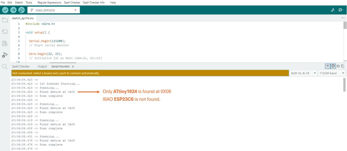
My Finding : This issue persist with all XIAO ESP32C6 boards that I checked. The same board works as Main however it does not work as Subordinate in the network.
Thus, I replaced the Subordinate 2 with ATtiny1624 and I was able to communicate between three nodes. Below is the network details and the arduino code.
My instructor Saheen Palayi identified the rootcause. We need to use Espressif-Ide to program the Subordinate XIAO ESP32C6 to work as receiver. I plane to do this and document it after my final project completion.
New Network Setup
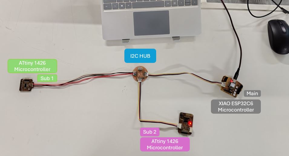
| Device | Controller | Button | Status LED | I2C Pins |
|---|---|---|---|---|
| Main | XIAO ESP32C6 | D8 (Active High) | D7 | SDA → D4 SCL → D5 |
| Subordinate 1 | ATtiny1624 | - | PA5 | SCL → PB0 SDA → PB1 |
| Subordinate 2 | ATtiny1624 | - | PA3 | SDA → PB0 SCL → PB1 |
#include
#define LED_PIN PIN_PA3      // PA5 pin where LED is connected
#define I2C_ADDR 0x09  // I2C address for this device

volatile uint8_t command = 0;  // Stores received command (volatile → used in interrupt)


// ── I2C Receive Callback ───────────────────
void receiveEvent(int howMany) {

  if (Wire.available()) {
    command = Wire.read();  // Read incoming command byte
  }
}


void setup() {
  pinMode(LED_PIN, OUTPUT);  // Set LED pin as output
  Wire.begin(I2C_ADDR);  // Initialize as I2C Subordinate
  Wire.onReceive(receiveEvent);  // Register callback when data is received
}


void loop() {
  if (command == 2) {
    // If command is 2 → blink LED

    blinkTwice();  // Call blink function
    command = 0;   // Reset command after execution
  }
}


// ── Blink LED twice ────────────────────────
void blinkTwice() {
  for (int i = 0; i < 2; i++) {

    digitalWrite(LED_PIN, HIGH);  // Turn LED ON
    delay(200);  // Keep it ON for 200ms
    digitalWrite(LED_PIN, LOW);  // Turn LED OFF
    delay(200); // Keep it OFF for 200ms
  }
}
How the communication / main and sub addressing works:
- Subordinate - 1 address in the firmware of main microcontroller and subordinate micro-controller must be same. Here it is 0X08.
- Subordinate - 2 address in the firmware of main microcontroller and subordinate micro-controller must be same. Here it is 0X09.
- Wire.begin( ) initializes the I2C communication - this command shall be there in all three firmware in void setup( ). Without this the I2C communication will not start.
- In main micro-controller, Button pin Pin D8 is initialized as input, in subordinate 1 micro-controller the PA5 is initialized as LED output, and in subordinate 2 the pin PA3 is initialized as LED output.
- Once initialized, the main micro-controller firmware will monitor button status.
- When the Button is short-press (less than 500ms), the subordinate 1 LED will blink twice, if the Button is Long-press (more than 500ms), the subordinate 2 LED will blink twice.
Adding Local Input and Outputs
Now I tried to add pulse/heart beat sensor as an analog input to my main board XIAO ESP32C6 and blink the charlieplexing matrix based on heart beats.
Pulse/heart beat Sensor → ESP32C6 reads analog → sends level via I2C → ATtiny lights bars of Charlieplexing Matrix
- XIAO ESP32C6 → Main (sender)
- ATtiny1624 → Subordinate (receiver + LED driver)
ChatGPT AI prompt: "Hey, Can you give me two codes one for XIAO ESP32C6 and one for ATtiny 1624. I have connected them using I2C and Pins used in ATTiny are SDA is PB1 and SCL is PB0. I want to Blink Charleiplexing, with raw value changing between 1550 to 1670, the bars rising and falling according to these raw values. Please update the threshold to 1640 for the pulse sensor. The Raw values are changing between 1550 to 1670 with by heart beats. Please give ATtiny 1624 code with explanation comments in each lines. Instead of Master and Slave please use Main/Subordinate terminology."
#include <Wire.h>
#define PulseSensorPin  0      // Analog input pin
#define I2C_ADDR        0x08   // Subordinate address

int Signal;

// Your observed range
#define MIN_SIGNAL 1550
#define MAX_SIGNAL 1670

void setup() {
  Serial.begin(115200);

  Wire.begin(22, 23);
  // Initialize I2C as Main (SDA=22, SCL=23)

  Serial.println("ESP32 Main Ready");
}

void loop() {

  Signal = analogRead(PulseSensorPin);
  // Read pulse signal

  Serial.println(Signal);

  // Map signal to 0–5 levels (bars)
  int level = map(Signal, MIN_SIGNAL, MAX_SIGNAL, 0, 5);

  // Constrain to safe range
  level = constrain(level, 0, 5);

  // Send level to subordinate
  Wire.beginTransmission(I2C_ADDR);
  Wire.write(level);
  Wire.endTransmission();

  delay(30);
}
#include <Wire.h>
#define I2C_ADDR 0x08
#define THRESHOLD 1640

// ── Charlieplex Pins ─────────────────────────
const uint8_t CHARLIE_PINS[] = { PIN_PA1, PIN_PA2, PIN_PA3, PIN_PA6, PIN_PA7 };
const uint8_t NUM_PINS = 5;

// ── LED Struct ───────────────────────────────
struct LED {
  uint8_t anode;
  uint8_t cathode;
};

// ── LED Mapping (your tested mapping) ───────
const LED LED_TABLE[5][4] = {
  { {PIN_PA2, PIN_PA3}, {PIN_PA1, PIN_PA3}, {PIN_PA7, PIN_PA3}, {PIN_PA6, PIN_PA3} },
  { {PIN_PA3, PIN_PA2}, {PIN_PA1, PIN_PA2}, {PIN_PA7, PIN_PA2}, {PIN_PA6, PIN_PA2} },
  { {PIN_PA3, PIN_PA1}, {PIN_PA2, PIN_PA1}, {PIN_PA7, PIN_PA1}, {PIN_PA6, PIN_PA1} },
  { {PIN_PA3, PIN_PA7}, {PIN_PA2, PIN_PA7}, {PIN_PA1, PIN_PA7}, {PIN_PA6, PIN_PA7} },
  { {PIN_PA3, PIN_PA6}, {PIN_PA2, PIN_PA6}, {PIN_PA1, PIN_PA6}, {PIN_PA7, PIN_PA6} },
};

// ── Active LED Buffer ───────────────────────
struct ActiveLED {
  uint8_t row;
  uint8_t col;
};

ActiveLED activeBuffer[20];
uint8_t activeCount = 0;

// ── Received signal ─────────────────────────
volatile uint16_t signalValue = 0;


// ── ALL OFF ─────────────────────────────────
void allOff() {
  for (uint8_t i = 0; i < NUM_PINS; i++) {
    pinMode(CHARLIE_PINS[i], INPUT);
  }
}


// ── CLEAR BUFFER ────────────────────────────
void clearAll() {
  activeCount = 0;
  allOff();
}


// ── ADD LED TO BUFFER ───────────────────────
void setLED(uint8_t row, uint8_t col, bool state) {

  uint8_t r = row - 1;
  uint8_t c = col - 1;

  if (state) {
    if (activeCount < 20) {
      activeBuffer[activeCount].row = r;
      activeBuffer[activeCount].col = c;
      activeCount++;
    }
  }
}


// ── MULTIPLEX ENGINE ────────────────────────
void multiplex() {

  if (activeCount == 0) {
    allOff();
    return;
  }

  for (uint8_t i = 0; i < activeCount; i++) {

    LED led = LED_TABLE[activeBuffer[i].row][activeBuffer[i].col];

    allOff();

    pinMode(led.anode, OUTPUT);
    pinMode(led.cathode, OUTPUT);

    digitalWrite(led.anode, HIGH);
    digitalWrite(led.cathode, LOW);

    delayMicroseconds(400);
  }
}


// ── RECEIVE I2C DATA ────────────────────────
void receiveEvent(int howMany) {

  if (Wire.available() >= 2) {

    uint8_t high = Wire.read();
    uint8_t low  = Wire.read();

    signalValue = (high << 8) | low;
  }
}


// ── TURN ON FULL MATRIX ─────────────────────
void turnAllOn() {

  clearAll();

  for (uint8_t r = 1; r <= 5; r++) {
    for (uint8_t c = 1; c <= 4; c++) {
      setLED(r, c, true);
    }
  }
}


// ── SETUP ───────────────────────────────────
void setup() {

  allOff();

  Wire.begin(I2C_ADDR);
  Wire.onReceive(receiveEvent);
}


// ── LOOP ────────────────────────────────────
void loop() {

  if (signalValue > THRESHOLD) {

    // FULL MATRIX ON
    turnAllOn();

    unsigned long start = millis();
    while (millis() - start < 300) {
      multiplex();
    }

    // OFF phase
    clearAll();

    start = millis();
    while (millis() - start < 200) {
      multiplex();
    }
  }
  else {
    clearAll();
    multiplex();
  }
}
🤝 Group Assignment
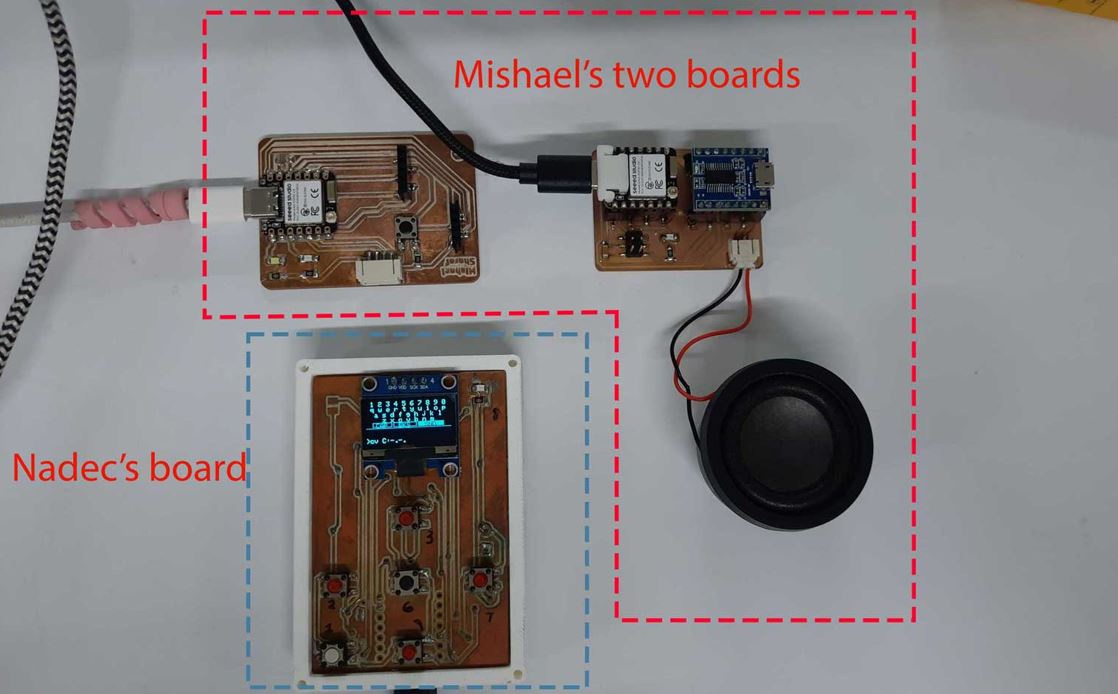
For this week's group assignment, our goal was to establish communication between two previously developed projects. To achieve this, both projects first needed to agree on a common communication protocol so they could exchange data in a format that each device could understand. Once the protocol was defined, we configured both systems to transmit and receive information correctly. Finally, we tested the complete setup to verify that messages were being exchanged accurately and reliably between the two devices.
View Group Assignment Documentation
📚 Key Learning Outcomes
Communication goal → Decide approach → Implementation → Test
- Agreement on common data exchange protocol.
- Configured both systems to send and receive data.
- Validated successful end-to-end communication.
Design Files Download Links
- I2C Hub KiCad design files kicad_pro, kicad_sch, and kicad_pcb
Useful Links
- FA26 Networking and Communications Class : Link
- XIAO LoRa Boothcamp : Link
- Getting Started - Meshtastic : Link
- Seeed Meshtasic Contest : Link
- Reference Assignment 1 : Link
- Reference Assignment 2 : Link
- Friend Finder reference : totem.labs
- Final Project Reference : Link
- Interactive textile designer & sensor spinster : Link
- Link Invasive connector : Link
- All Communication Protocols in 6 mins : Link