What I did in Week 02
This week's focus centered on deepening understanding of 2D and 3D CAD principles. We explored various digital modeling platforms and emphasized preparing and optimizing graphic outputs in efficient media formats.
- 2D software: tried raster and vector tools for drawing and editing.
- 2D software: tried CAD2D to develop some initial geometry.
- 3D software: explored modeling tools and parametric workflows.
- Rendering: explored visual language for the final project.
- Compression: standardized image and video sizes and formats.
- Final project concept: modeled & rendered ideas for the final project.
- Model (raster, vector, 2D, 3D, render, animate, simulate, ...) a possible final project.
- Compress images and videos, and post a description with design files on the class page.
Computer Aided Design
Here I will show some differences between some 2D and 3D programs that I use, and with this you will understand the reason for using the programs in which I made my 2D and 3D designs.
2D software
| Revit | AutoCAD |
|---|---|
| Lines and shapes: You draw independent strokes that represent objects. | Elements: You draw walls, doors, and windows that contain data. |
| Manual changes: If you change something in the floor plan, you must correct it manually in the section. | Automatic: If you change the floor plan, the section and elevation are updated automatically. |
| The drawing only has graphic properties (color, thickness). | The object knows its material, cost, height, and manufacturer. |
| Technical drawing: Ideal for construction details or quick drawings. | Ideal for coordinating an entire design project. |
3D software
| Revit | FUSION 360 |
|---|---|
| Buildings: Walls, levels, floors, and piping systems. | Parts and products: Mechanical components, housings, and prototypes. |
| Macro: Meters and centimeters. Designed for large projects. | Micro: Millimeters and microns. Designed for mechanical precision. |
| Parametric Architectural: Based on construction rules. | Mechanical Modeling: Based on sketches and assemblies. |
| Plans and construction: Technical documentation for building construction. | Manufacturing: Files for 3D printing, CNC, or laser cutting. |
With all the information in the tables, you can get a clearer idea of what each software can be used for. In my case, I prefer to use Revit because, due to my work and training, I have more experience using that software.
Computer Aided Design 3D
For this activity I will design a modular structure for an anthill which can continue to grow as more modules are added. I will design this structure in the Revit software.
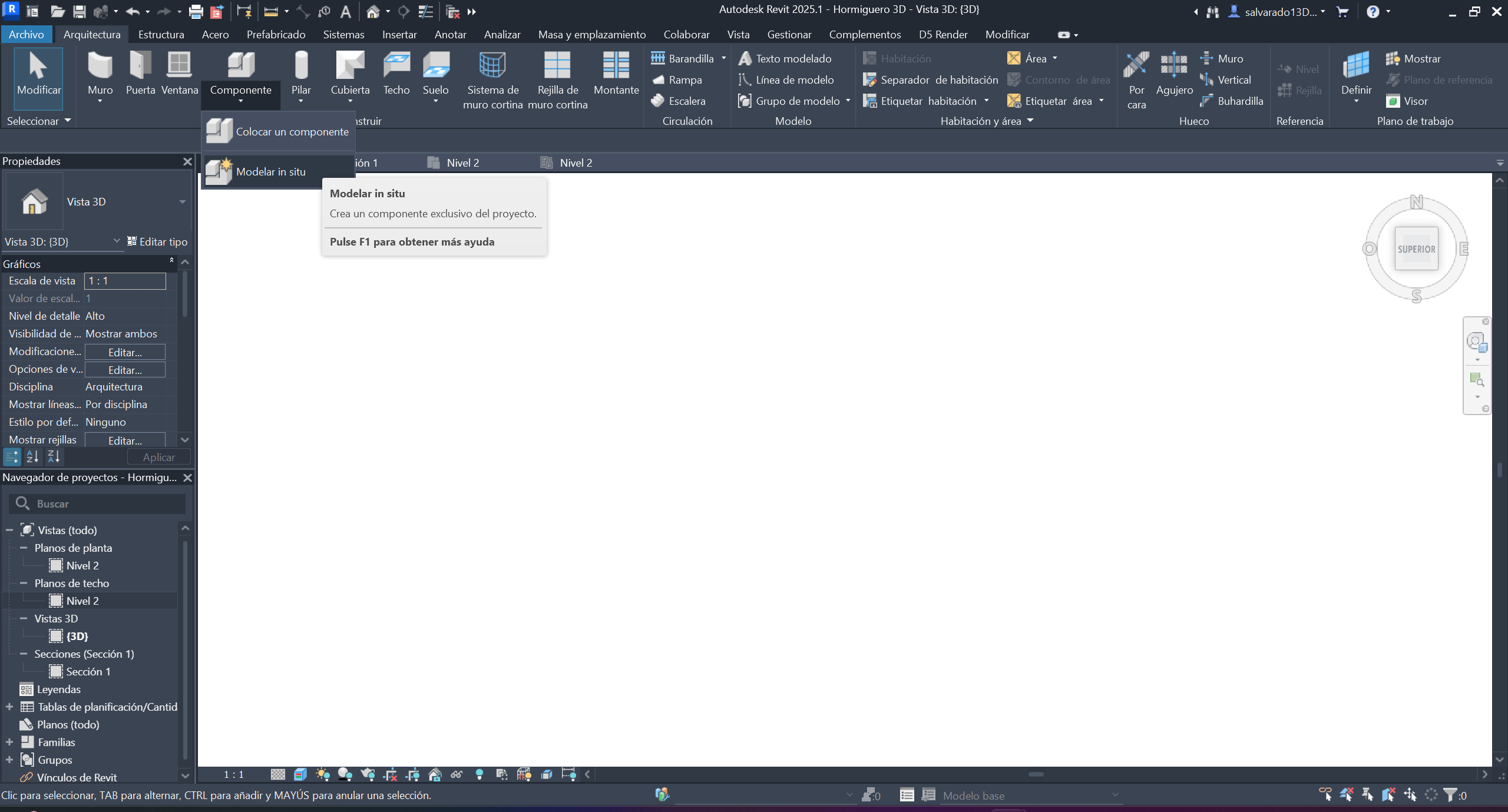
Step 1 ·
We open Revit and create an in-situ component
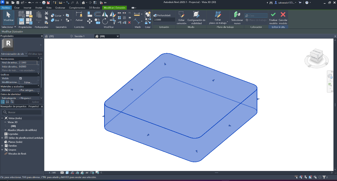
Step 2 ·
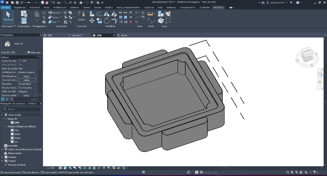
We place it in EXTRUSION mode, creating the shape with the required measurements and depth.
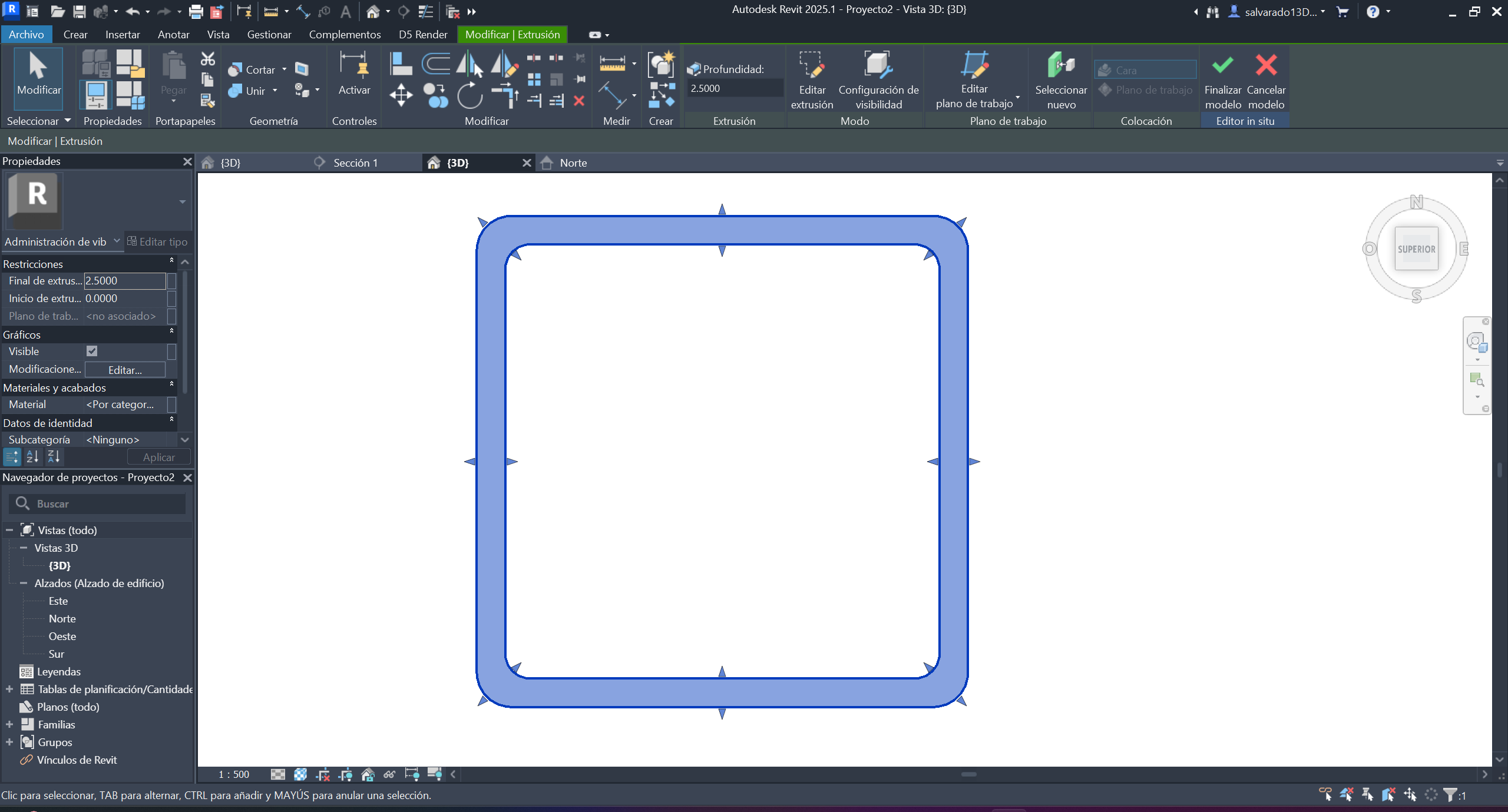
Step 3 ·
We edited the extrusion to create the main shapes.
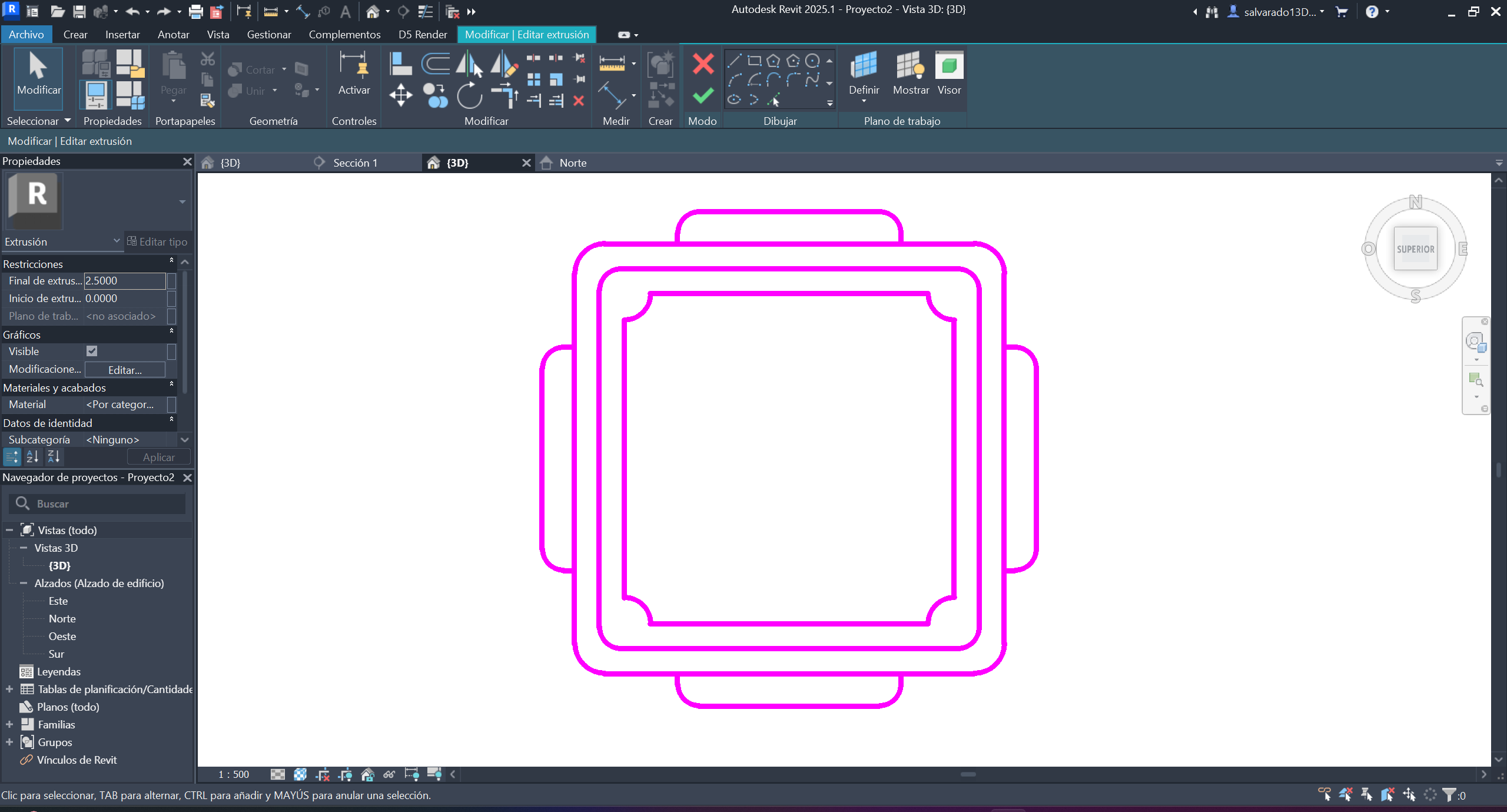
Step 4 ·
We created the base of the model with simple geometric shapes and joins at the corners.
Step 5 ·
We calculated the heights and depth of each one, taking into account the measurements of the pieces that will be used.
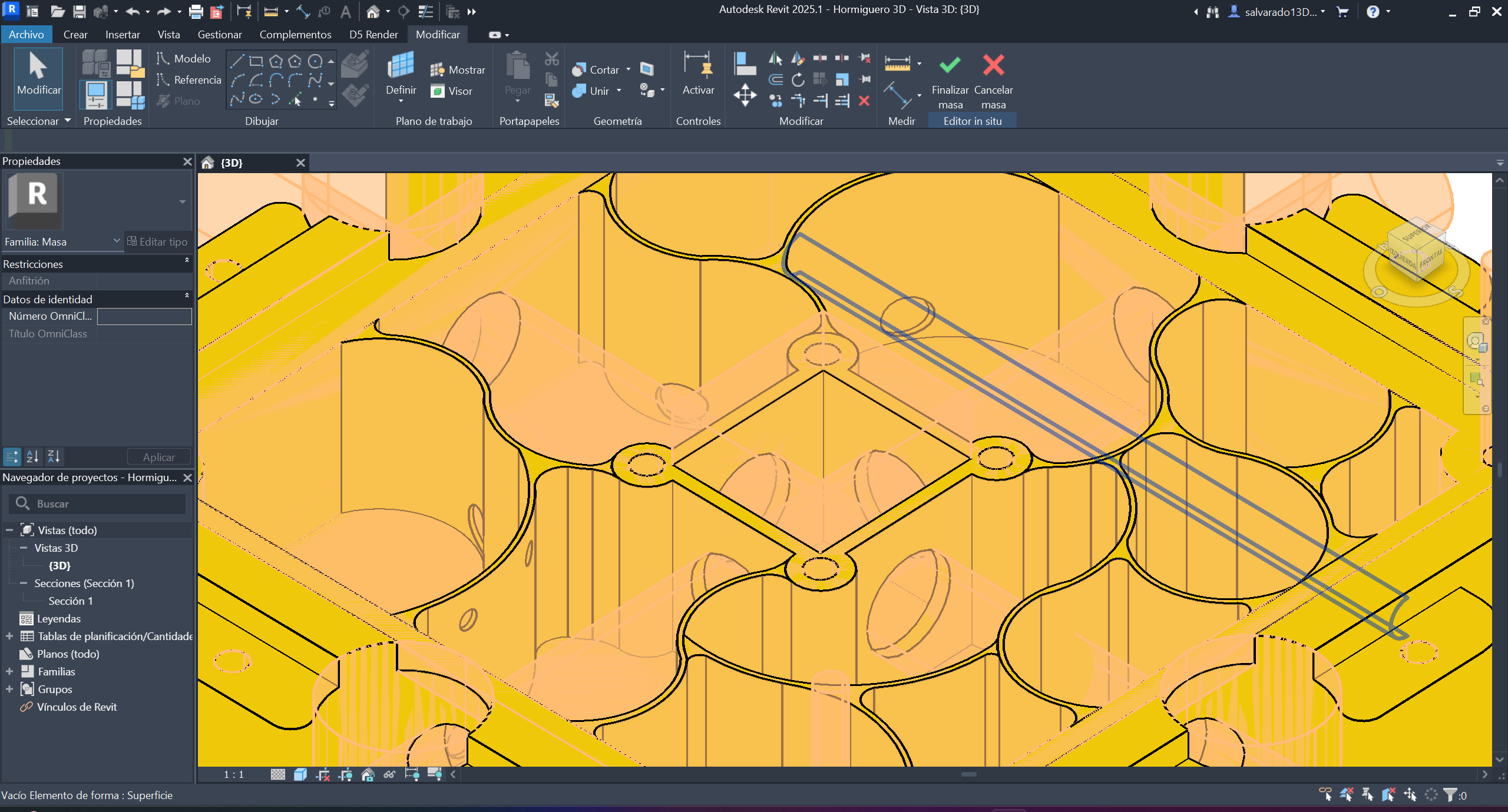
Step 6 ·
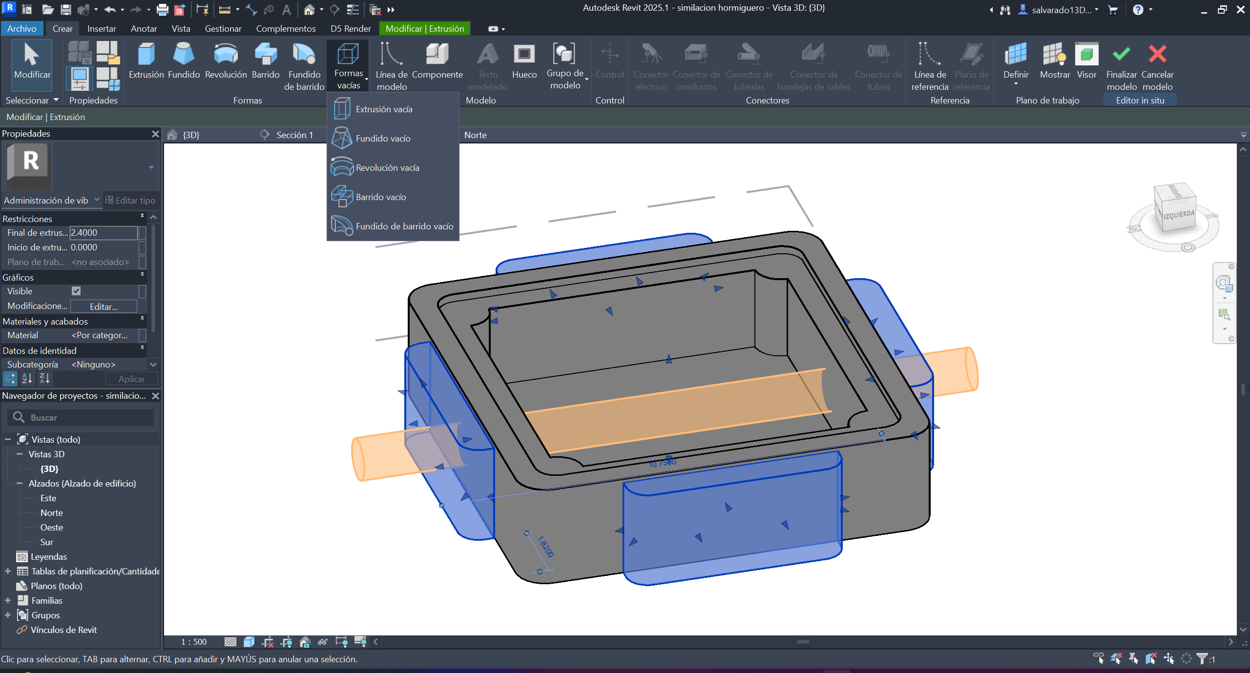
We created an empty shape with a depth that left a gap, which would be the path for the ants.
Step 7 ·
We placed more empty shapes in the other locations to connect similar modules and the constraints of the other gear pieces.
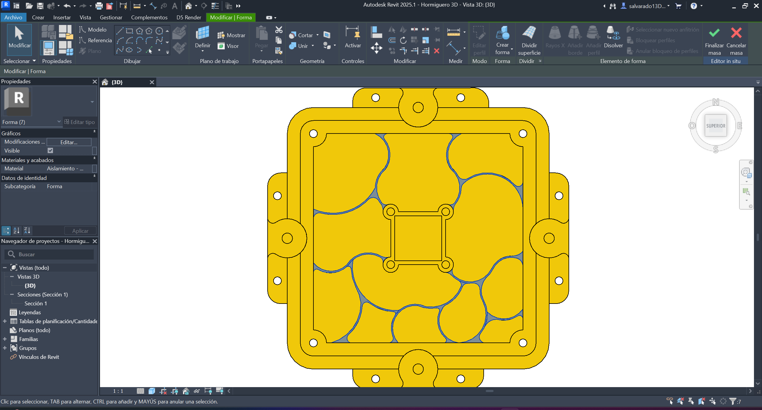
Step 8 ·
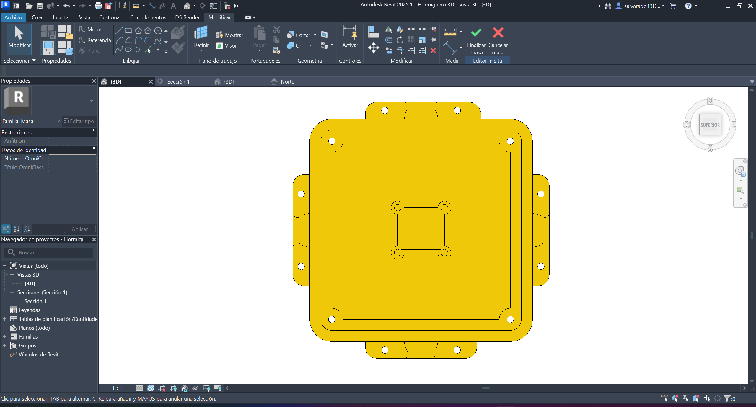
Once the necessary perforations have been made in the hollow forms, it would look like this from a top view. These perforations are crucial for joining more similar modules.
Step 9 ·
Now, in the top view, we create the piece, raising the walls that aren't linear to avoid sharp corners. We give it a height that reaches the same edge as the exterior walls, since an acrylic panel will go on top of these walls.
Step 10 ·
This is how the walls looked, built to the same depth to place the acrylic on top.
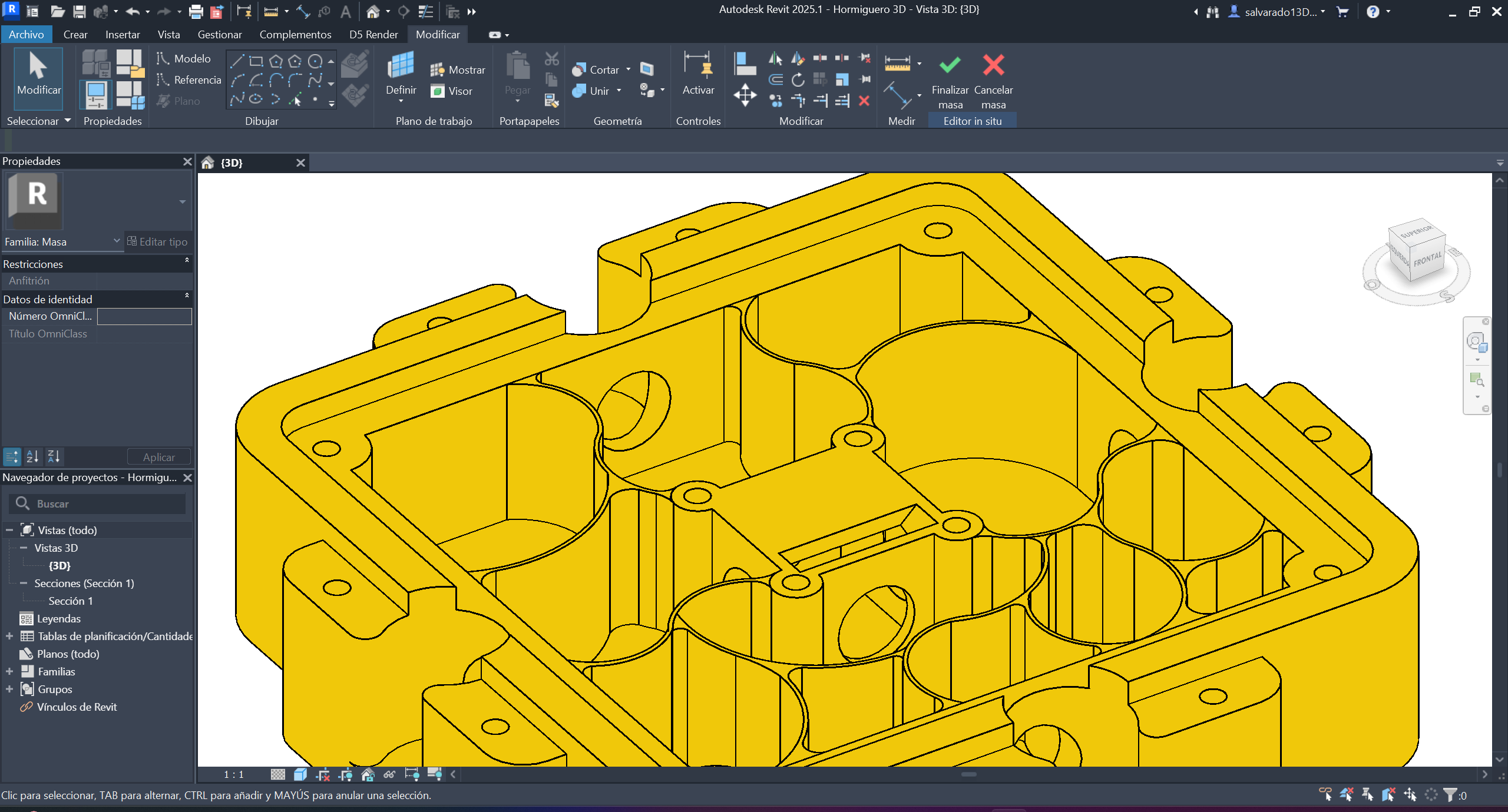
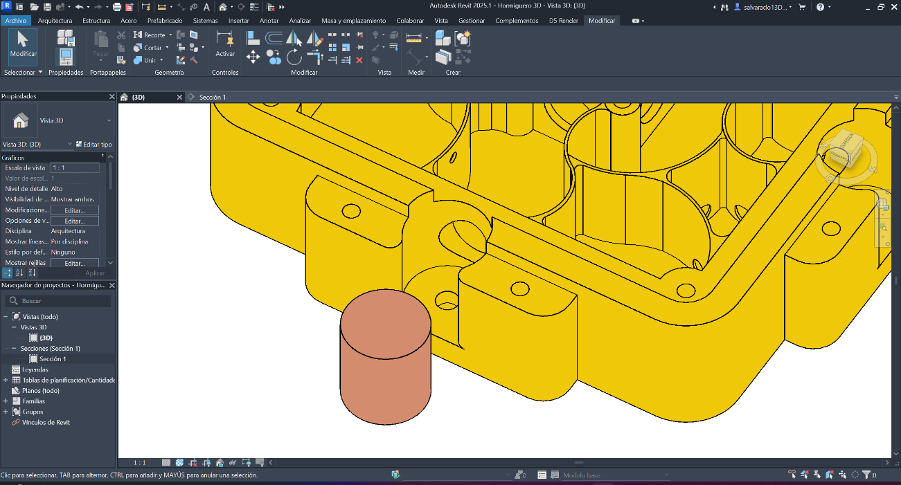
Step 11 ·
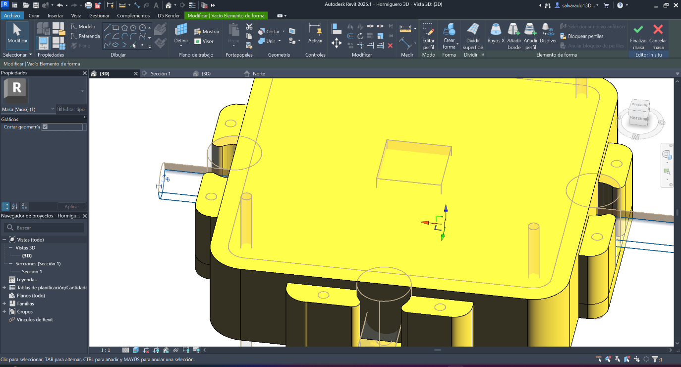
Once the walls were built, we placed more cylindrical, hollow shapes for the ants to pass through. We created hollow shapes that intersected between all the walls to facilitate movement between spaces.
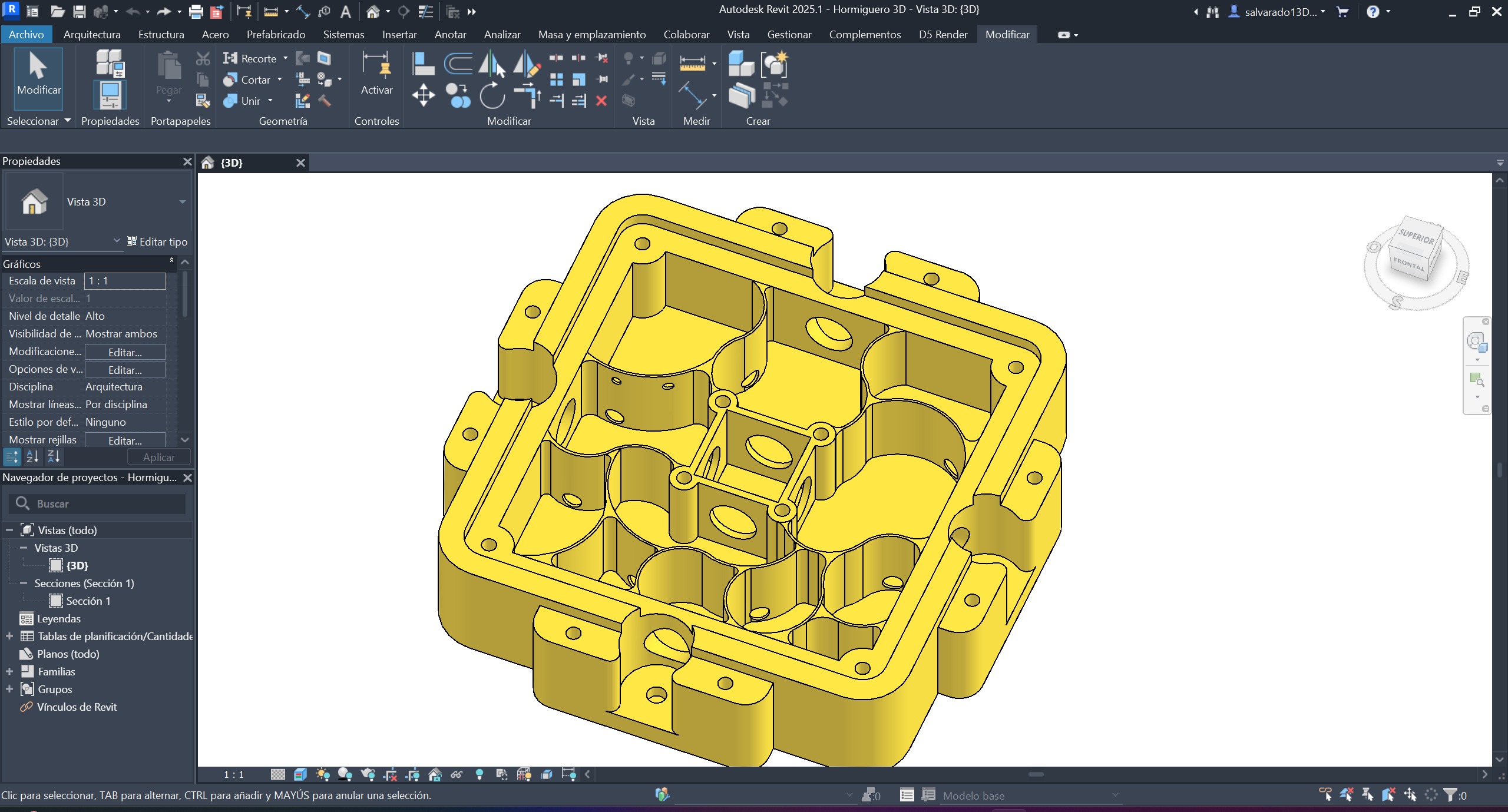
Step 12 ·
This would be the result of the main piece; now we just need the pieces that complement it.
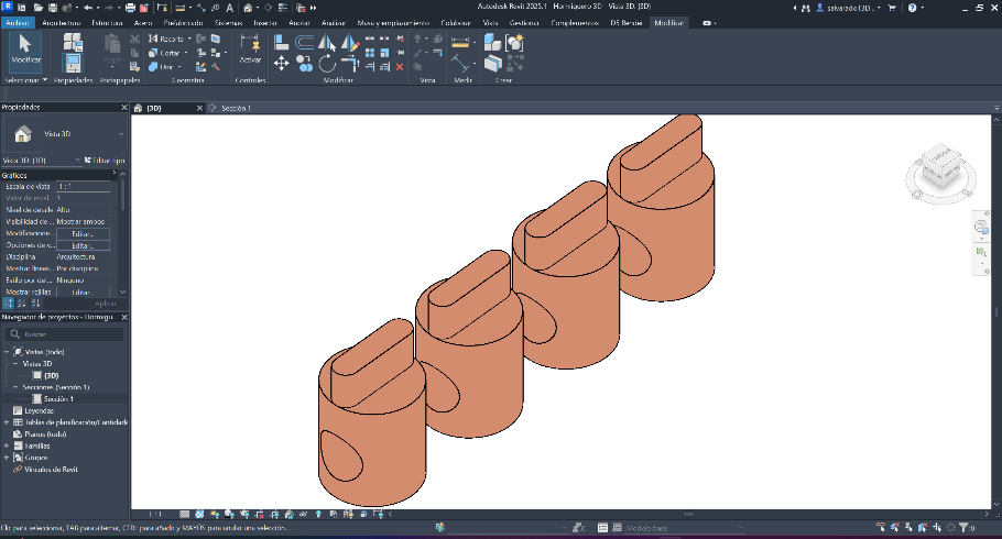
Step 13·
Now we create the complementary pieces that go on its four sides, which allow the passage to be opened and closed for the modules that will be connected to its sides. We start with a cylindrical shape that fits.
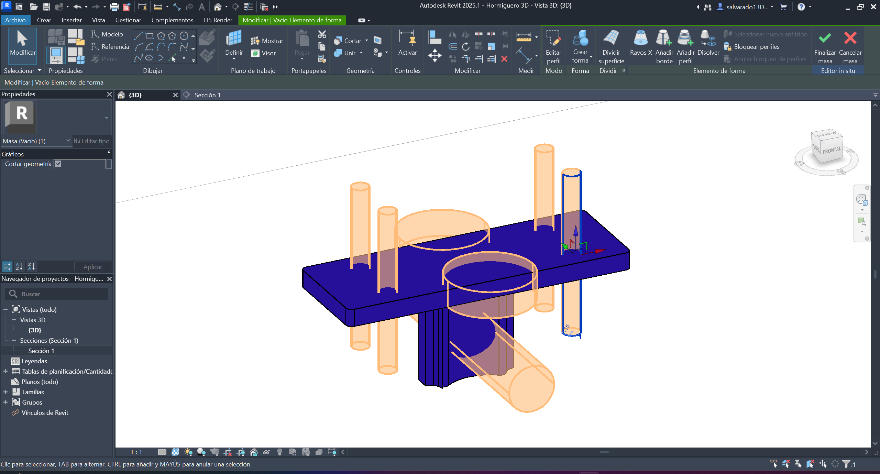
Step 14 ·
Now that the cylindrical shape fits the spaces where it goes, we make the perforations with empty shapes and a tab that helps to rotate.
Step 15 ·
We continue with the piece that connects the modules, in the same way with geometric figures and with the measurements that fit with the main piece.
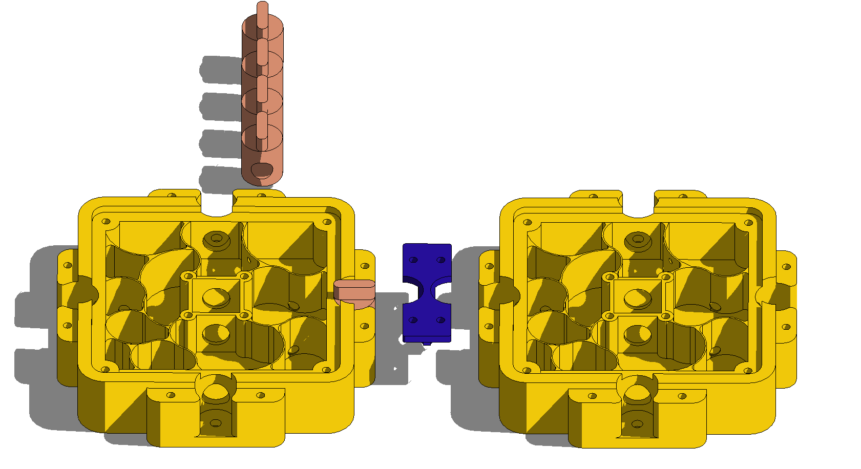
Step 16 ·
This is how the piece that connects to the main piece would look.
Image conversion and compression
On macOS, use the terminal and ImageMagick to batch convert and compress images.
# convert PNG to JPG:
convert input.png output.jpg

# convert all PNGs to JPGs:
mogrify -format jpg *.png

# convert SVG to PNG at 1000 DPI:
convert -density 1000 -units PixelsPerInch input.svg output.png

# compress JPG to quality 50% width 1000:
convert input.jpg -quality 50% -resize 1000 output.jpg

# compress all JPGs to quality 50% width 1000:
mogrify -quality 50% -resize 1000 *.jpg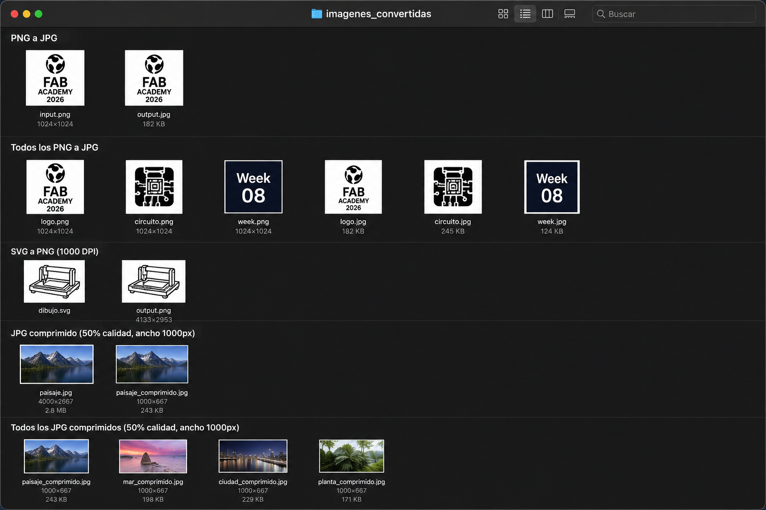
Progress of the final project
Computer-Aided Design (CAD) represents one of the foundational pillars of FabLab practice, bridging the gap between conceptual intent and physical fabrication. Within the FabLab methodology, CAD tools are not merely drafting instruments — they function as generative environments where ideas are tested, refined, and translated into precise digital geometries ready for machine execution. The ability to model in three dimensions, simulate structural behavior, and iterate on formal decisions before committing to material production is what makes CAD indispensable in this workflow. Every cut, joint, and component originates as a digital decision, meaning that the quality and rigor of the design process directly determines the outcome of fabrication. This section documents the initial geometric explorations and spatial intentions developed for the final project, using CAD as the primary thinking tool — a space where form, function, and fabrication logic converge before any physical process begins.
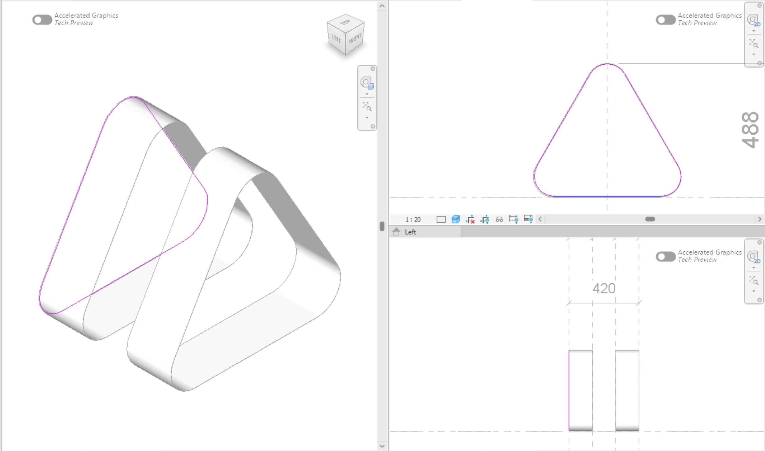
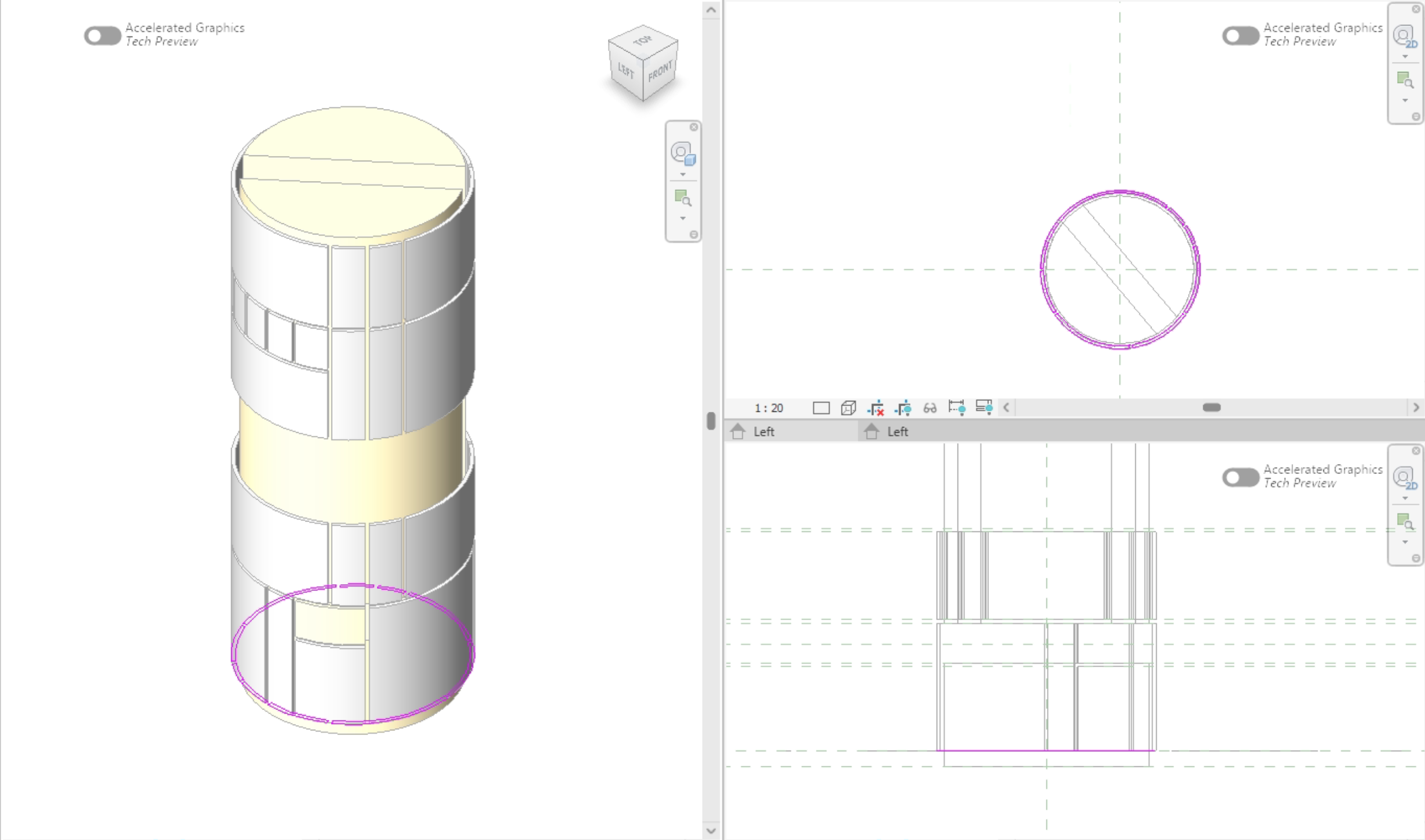
Step 1 · Geometry Exploration on Autodesk Revit3D
The initial geometric exploration was carried out in Revit, a platform deeply integrated into my daily architectural workflow and one that exemplifies the potential of computer-aided design as a generative tool in early-stage product development. The design intent deliberately departed from anthropomorphic references, pursuing a formal morphology capable of communicating the assistant's functional identity through geometry alone — a spatial language that signals purpose and intelligence without humanoid representation. Its parametric environment made it possible to model functional components in three dimensions, test spatial relationships, and evaluate how each element fits within the overall assembly, while enabling the systematic testing of innovative geometries for formal coherence and component hierarchy. Working within this CAD-driven workflow provided real-time feedback on proportions, clearances, and structural logic, making it an effective instrument for pre-dimensioning the design and understanding the mechanical behavior of the system before committing to a final form. This computational approach allowed morphological decisions to be tested progressively, ensuring the resulting formal language satisfies both functional criteria and operates as a legible communicative device — one that orients the user through the internal logic of its geometry rather than cultural or figurative convention.
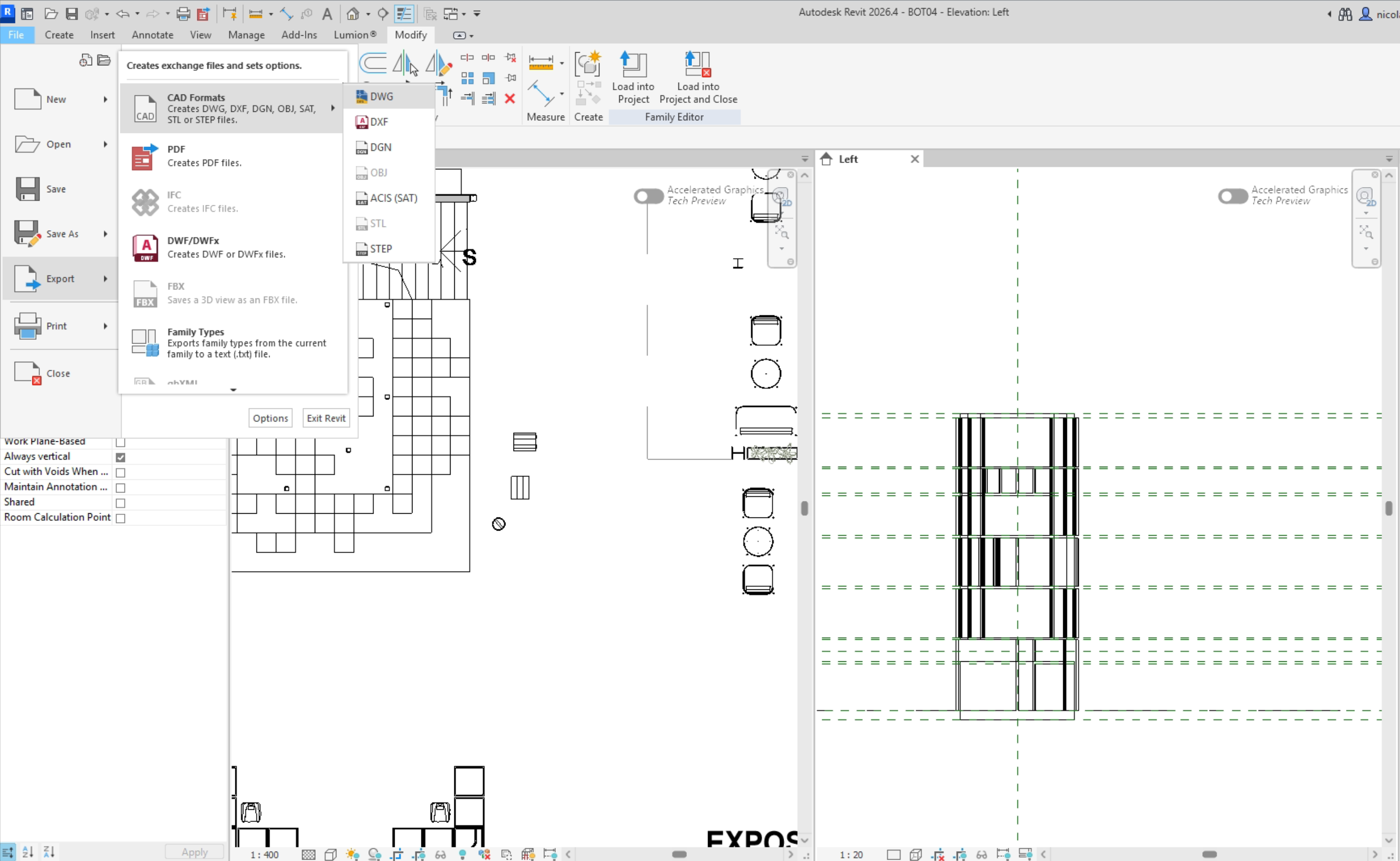
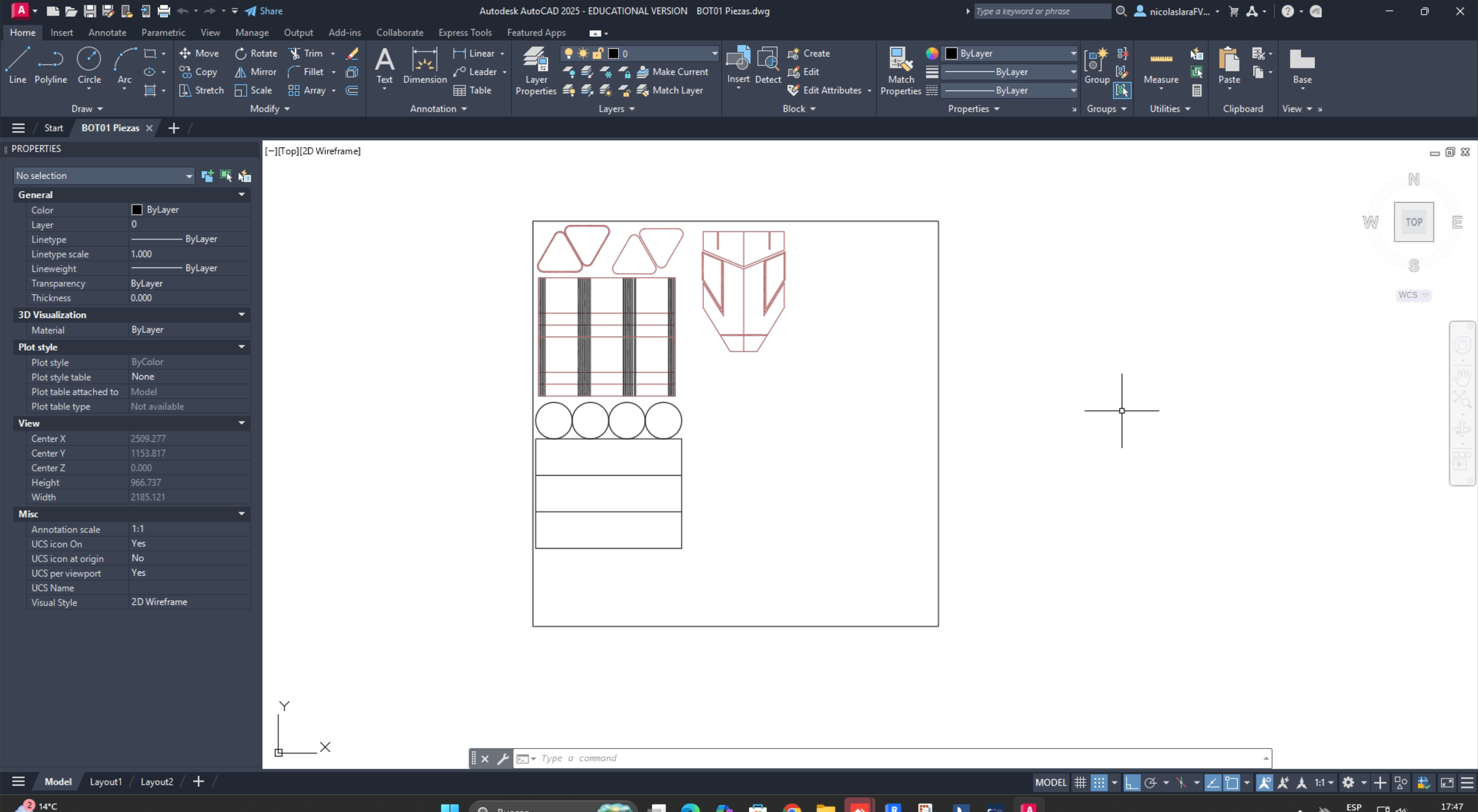
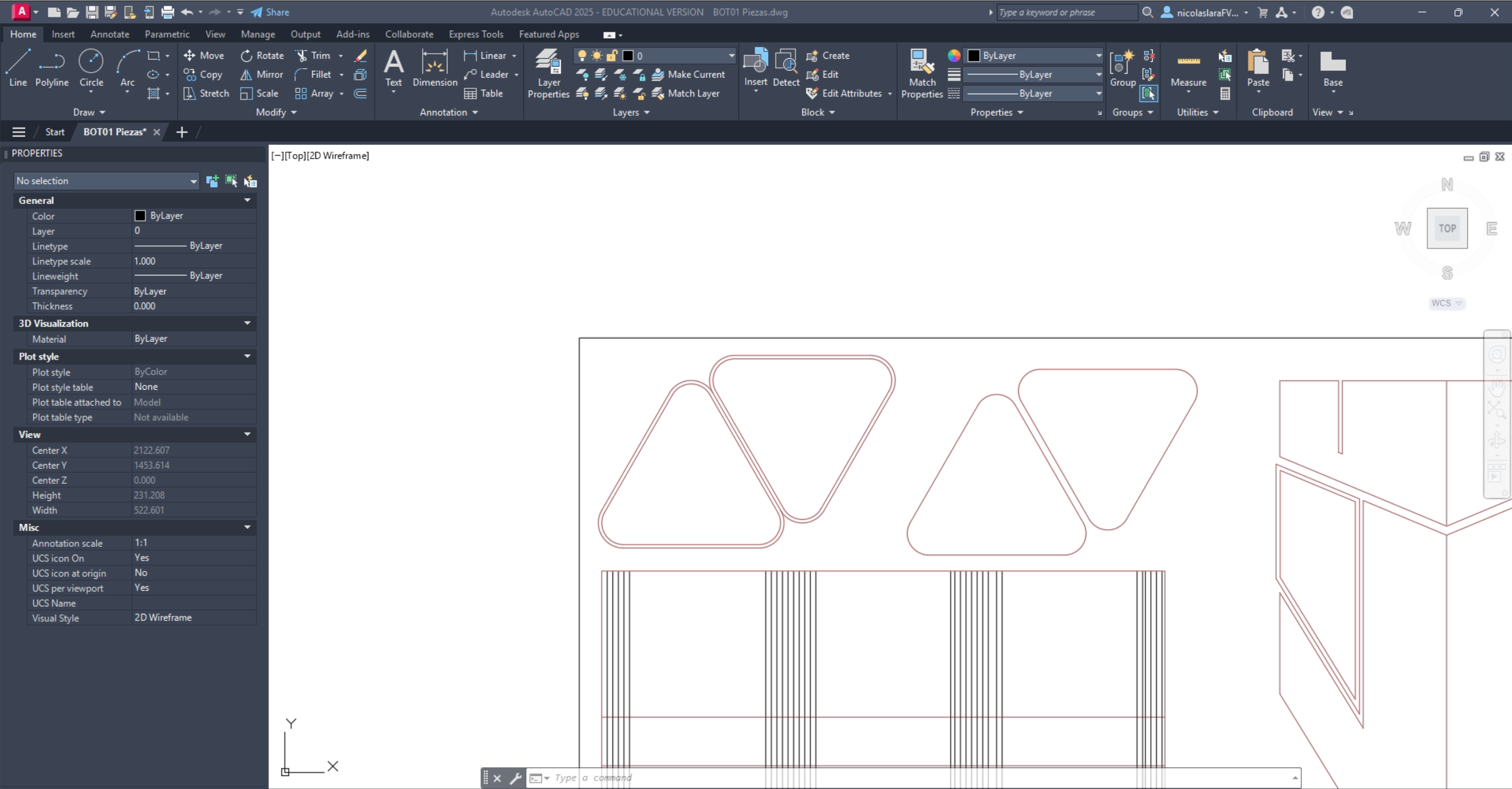
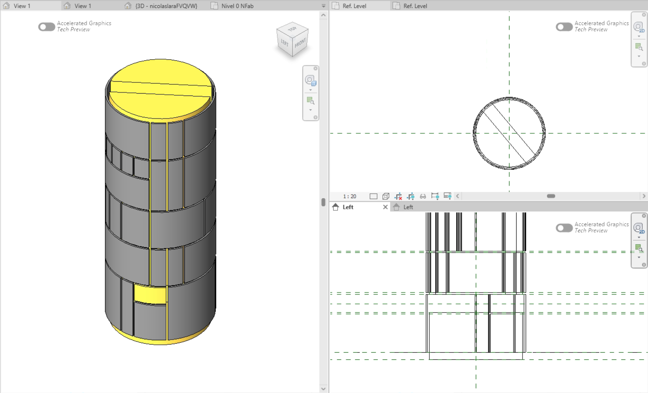
Step 2 · Export to AutoCAD for model testing.
With the spatial dimensions established, the workflow shifted to AutoCAD to translate the 3D understanding into precise 2D layouts. This transition was made possible in part by Revit's versatile export capabilities, allowing geometry developed in three dimensions to be seamlessly transferred into a CAD drafting environment across formats such as DWG and DXF. In preparing files for laser cutting, 2D geometry is assigned specific color attributes that communicate fabrication instructions directly to the machine — red lines define cut paths while black lines indicate engraving areas, translating design intent into a clear operational language the laser cutter interprets with precision. These technical drawings served as the basis for cutting and assembling physical model pieces, enabling a hands-on exploration of the design at scale and validating decisions through a tangible artifact.
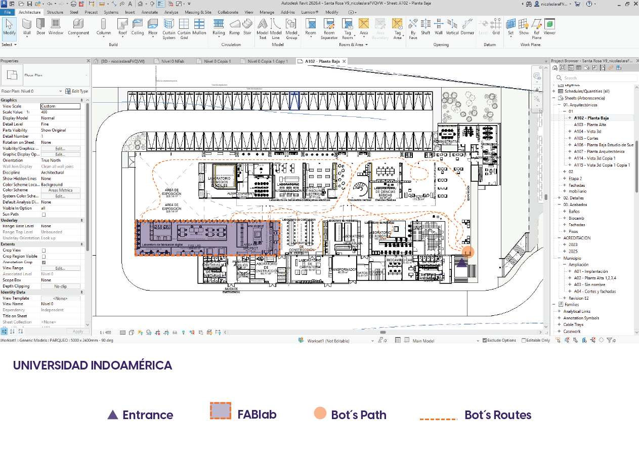
Step 3 · Design & Campus life.
The third dimension of this exploratory phase considers the relationship between the object and its intended context. The final product will be located at Universidad Indoamérica's Tech Campus — a dynamic, multi-disciplinary environment that houses the laboratories, workshops, and fabrication spaces serving the university community. This setting imposes a broad range of functional demands, as the campus brings together students, educators, and practitioners with diverse and simultaneous needs. The design must therefore be conceived not as a static solution but as an adaptive artifact, capable of responding to the varying rhythms and requirements of a highly active academic and technical environment. Understanding this context from the outset ensures that spatial, ergonomic, and operational considerations are embedded into the design logic from the beginning.
Conclusions
This week, I explored different CAD software functions and understood how each type of software contributes to the digital manufacturing process. Working with 3D modeling tools, both vector and raster, helped me compare their advantages and identify which are best suited for specific design tasks, such as illustration, technical drawing, rendering, and parametric modeling. I also improved my understanding of 3D modeling by creating and refining a potential final project concept using CAD software and visualization tools. This week strengthened my design workflow and provided me with a better foundation in digital modeling and creativity.