12 Mechanical design
Group assignment
Video
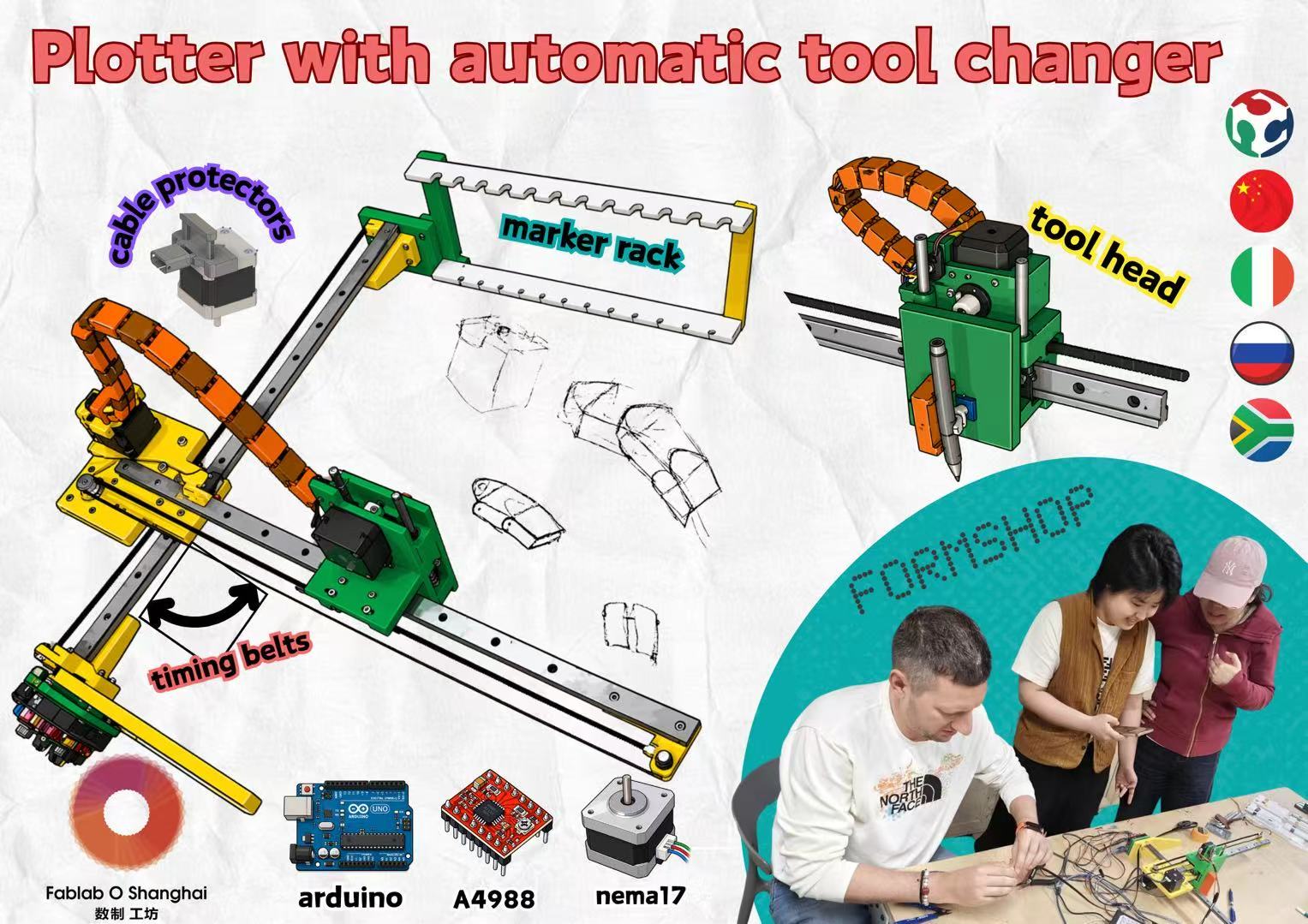
Poster
Mechanical Design (part 1 of 2)
- Group assignment:
- Design a machine that includes mechanism + actuation + automation + application
- Build the mechanical parts and operate it manually
- Document the group project
- Individual assignment:
- Document your individual contribution
Machine Design (part 2 of 2)
- Group assignment:
- Actuate and automate your machine
- Document the group project
- Individual assignment:
- Document your individual contribution
Group assignment
This is our group assignments link: https://fabacademy.org/2026/labs/formshop/students/yaroslav-artsishevskiy/assignments/week12.html
Team Members and Responsibilities
I also checked other team members' documentation pages and added the main reference links here to connect my individual documentation with the group work records.
| Team member | Main responsibility | Page / reference |
|---|---|---|
| Yaroslav Artsishevskiy | Idea development, group documentation, and electrical design | Yaroslav's Week 12 group documentation |
| James Stewart | Assembly, testing, and poster design | - |
| Winnie Sun | Project organization and final video editing | - |
| Yanfeng Li | Arduino board container 3D modeling | - |
| Zequan Lin | Accessory design for wire protection | Zequan's Week 12 Mechanical Design documentation |
My Individual Contribution Summary
My contribution in this team project was mainly communication, following the modeling discussion, filming, and final video editing. Since part of the team discussion happened online and part of the work happened in the lab, I helped keep the process and documentation connected.
For the modeling support, I focused on two related pen-holder issues. First, I looked at the pen-holder frame support and proposed adding support to make the holder structure more stable. Second, I looked at the pen-clamping contact surface and proposed making this surface wider, so a small foam or rubber pad could be added later to increase friction.
This part was only a modeling suggestion. I did not have enough time to fabricate and test it on the actual machine. In the final stage, most of my work was still focused on communication, filming, and editing the final demonstration video.
 My idea is CPM (Continuous Passive Motion). Because i used it in hospital before. We have also produced many idea, but in fact, we don't know how to measure the time to be spent. At the suggestion of our tutor, we chose to complete a simple case to complete our online and offline synchronization.
This is our group brainstorm link:
Overview
Project Context
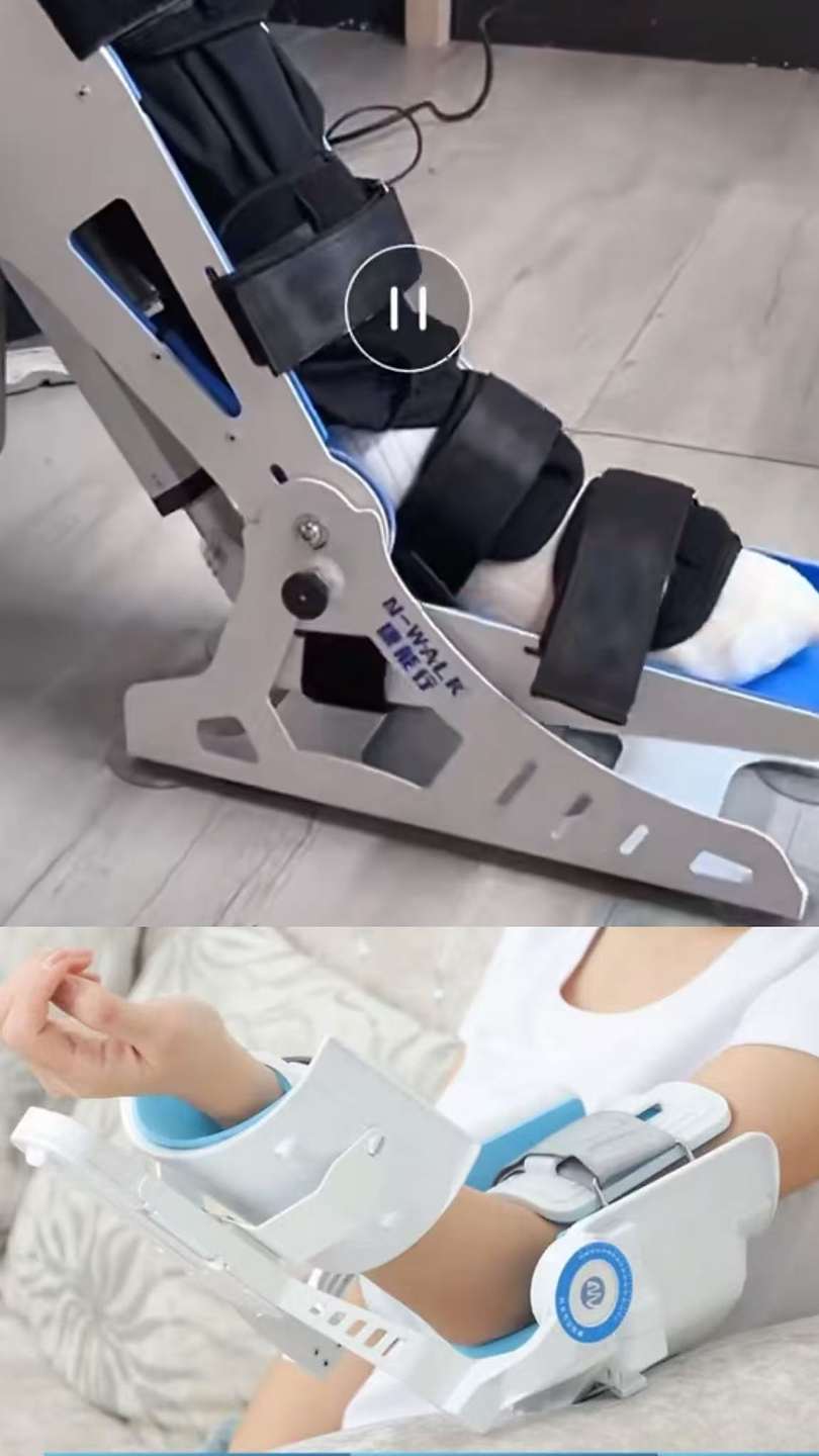
For the Week 12 & 13 group project, our team built a color drawing machine with an automatic tool-changer. Since our team was split between online and offline members, I acted as an information and communication bridge between remote design discussion and the physical fabrication process in the lab.
My main group contribution focused on:
- following the online/offline communication and checking whether the model discussion matched the physical machine condition;
- following the modeling discussion and adding small modeling support for the pen-holder frame support and the pen-clamping contact surface;
- collecting photos and videos from the team process and editing them into a clearer final demonstration video.
My Role in the Team
My contributions this week were mainly defined by the following four dimensions.
1. Communication Bridge
I followed the communication between the remote design intent and the physical fabrication reality in the lab. This helped me understand how the group adjusted the machine direction according to time, available parts, and fabrication constraints.
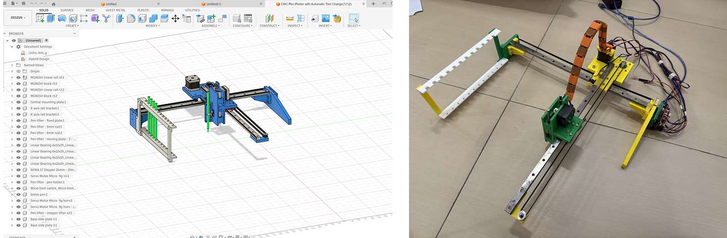
Figure: Online communication and process tracking during the group machine discussion.
2. Modeling Follow-up
I participated in discussions about the 3D model modifications and tried to understand how each modeling decision affected the mechanical constraints, assembly sequence, and stability of the machine.
Yanfeng part
Lin part
This process helped me understand that a machine model is not only a visual form. Each part needs to consider fabrication method, assembly clearance, rigidity, and how the moving parts will behave after installation.
3. Modeling Support: Pen-Holder Frame Support and Pen-Clamping Contact Surface
In addition to following the team model discussions, I tried two possible modeling directions for improving the pen holder. The first one was a simple support and contact-surface improvement based on the existing structure. The second one was a more integrated redesign if the holder needed to be printed as one stronger part.
Option 1: Simple Support and Contact-Surface Improvement
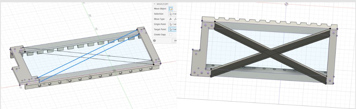
Figure: Modeling exploration for the pen-holder frame support. The left side shows the early diagonal support idea, and the right side shows the X-shaped support added to the pen-holder frame.
For the pen-holder frame support, the issue was structural stability. The original pen holder frame was a long rectangular structure, and it could twist or deform when the machine moved, especially when the pen pressed against the paper. To make the holder more stable, I explored adding extra support to the frame.
Option 2: More Integrated One-Piece Holder Redesign
After checking the simple support option, I also tried a more complete redesign direction. If the pen holder needed to be more stable, one possible direction was to make the holder wider and print the back plate, lower support, and holder body as a more integrated structure.
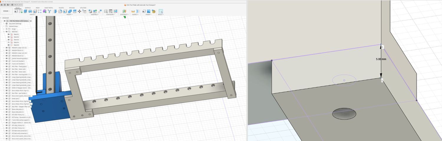
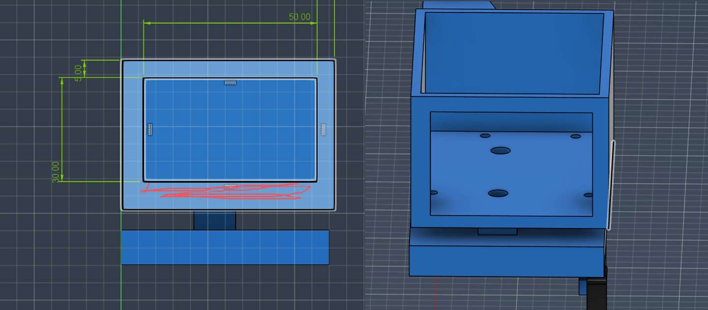
Figure: I first checked the original pen-holder frame and the thin support area. Some support areas were only about 5 mm thick, which felt too weak for a long holder.
I started by checking the old model size and the weak support area. The previous support was only about 5 mm, so I made a new version with a stronger back plate. The idea was to keep the original pen-slot frame and connection position, but rebuild the main support as a more stable part.
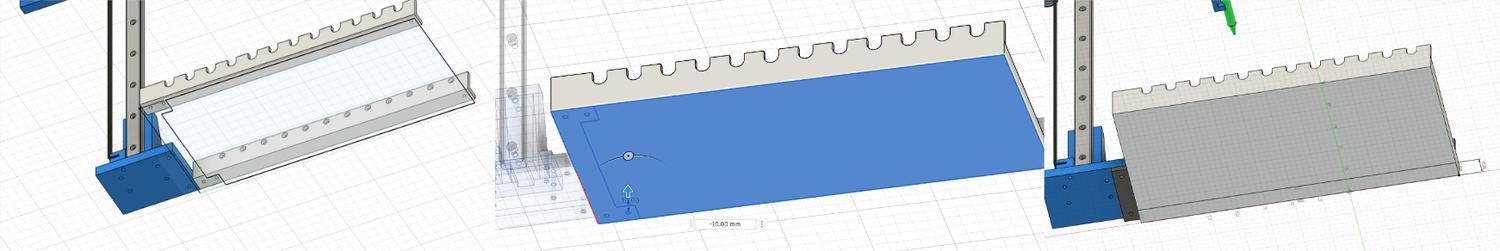
Figure: I used the original frame as the reference, projected the existing geometry, enlarged the back plate to around 10 mm, and started extending the lower support.
I hid the old support part and created a new sketch on the original frame. I used Project (P) to project the existing frame edges and hole positions into the sketch, then redrew the back plate as a 10 mm support surface. For the lower support, I first gave it about 15 mm of height, then used Extrude (E) to pull the support outward. After checking the shape, I felt the first version was still a bit small, so I manually extended the support further, roughly to around 40–50 mm, to give the holder a larger base.
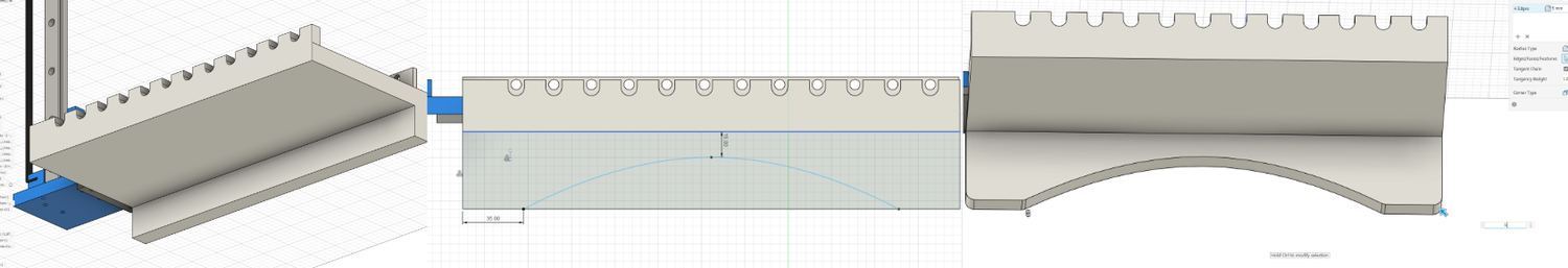
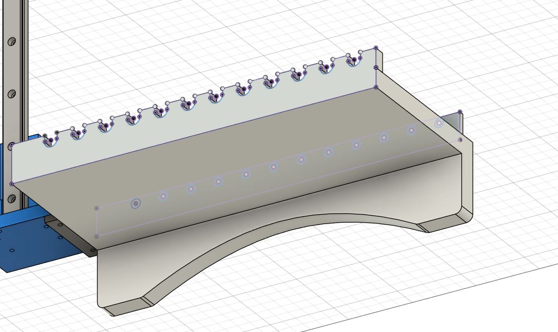
Figure: I added a larger lower support surface and used a curved cut to reduce material while keeping the holder more integrated.
For the bottom support shape, I created another sketch and used Line (L) and the Arc tool to draw a curved lower edge. The two lower sides needed more support, but I did not want the bottom part to look too heavy. After drawing the curve, I used Trim (T) to remove the extra sketch lines, and then used Extrude (E) with a cut operation to shape the lower opening. I also used Fillet (F) to round some sharp corners and make the model cleaner.
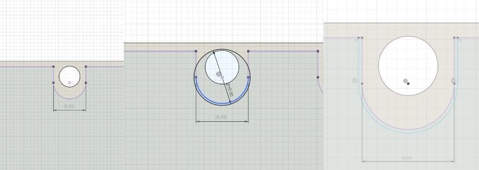
Figure: I enlarged the pen-slot openings because the original 9.3 mm slots were too tight for the thicker pens we used.
I adjusted the upper pen slots because the previous opening was about 9.3 mm, and the thicker pens did not fit smoothly. For this part, I used Circle (C), Line (L), and Trim (T) to redraw the slot shape and clean up the extra sketch lines. Then I made the opening slightly larger.
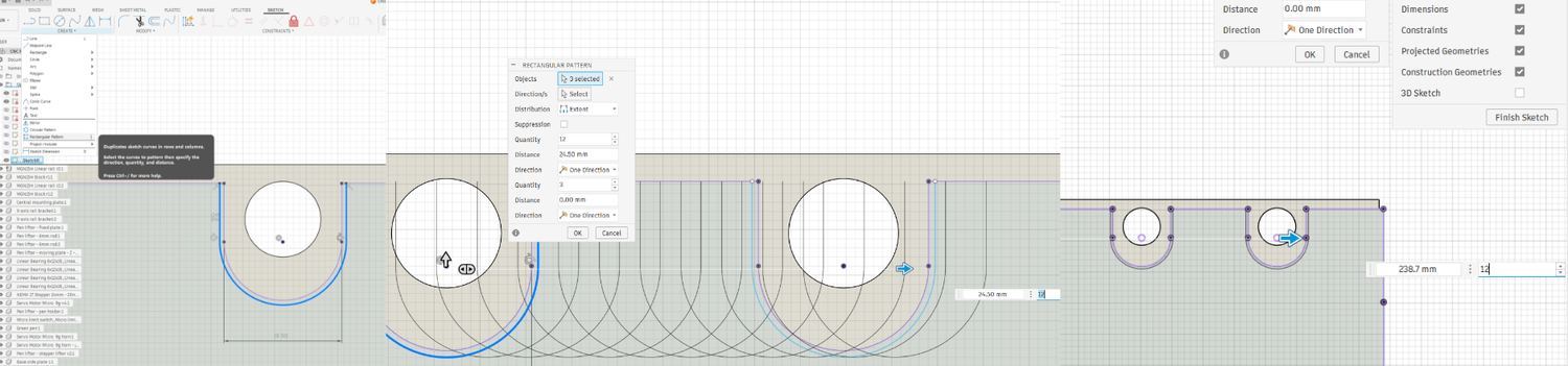
Figure: I used Rectangular Pattern to repeat the pen-slot geometry and keep the spacing more consistent.
The more complicated part was the repeated slots. For this, I used Create > Rectangular Pattern in the sketch tools. I first selected the sketch lines that needed to be repeated, then chose the pattern direction. After that, I entered the quantity, dragged the arrow roughly to the right position, and finally typed in the spacing value manually for a more accurate result. This was faster than measuring and drawing every slot one by one.
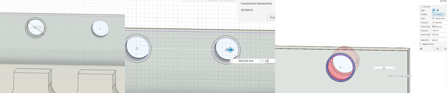
Figure: I enlarged the lower holes with larger circles and an Extrude Cut operation, then checked the fit in the full assembly.
I also enlarged the lower holes. The smaller holes were not friendly for thicker pen tips, so I increased them to about 7 mm. For this part, I did not need to trim sketch lines. I directly drew larger circles on the existing hole centers, adjusted the circle size, and then used Extrude (E) with the Cut operation to remove the center material. Finally, I checked the redesigned holder inside the full assembly. If the size looked slightly off, I used Scale from the S search menu to make small adjustments.
This second option kept the original pen-slot and mounting relationship, but made the holder wider, added a larger lower support area, and made the structure more suitable for a stronger one-piece print.
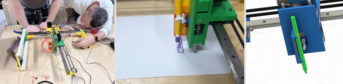
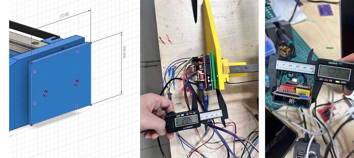
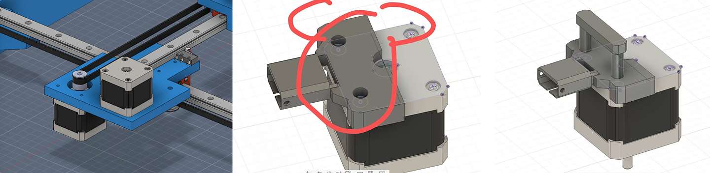
Figure: Physical prototype and modeling context for the pen-clamping contact surface.
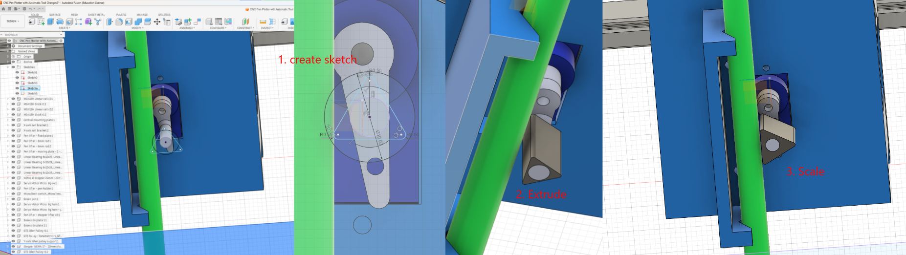 Figure: Fusion 360 modeling process for the pen-clamping contact surface. I worked from the existing round pushing rod, projected its position into a sketch, and tested a wider triangular contact surface as a possible add-on shape.
For the pen-clamping contact surface, I made a small modeling proposal based on the existing pen-holder mechanism. The idea was to keep the original structure mostly unchanged, and add a wider contact surface around the original round pushing rod.
-
I first created a new sketch near the original round rod. I used Project (
P) to project the rod position into the sketch, then drew a circle as a reference for the rod center and size. -
Based on this reference circle, I used Line (
L) and Dimension (D) to draw a triangular contact shape around the rod. After the sketch was roughly set, I used Fillet (F) to round the sharp corners a little, so the part would be less likely to catch on an edge when the mechanism moves. -
After finishing the sketch, I used Extrude (
E) to extrude the triangular shape along the rod direction, with a length close to the original rod/contact area. Then I checked the fit with the pen and holder, and used Scale from theSsearch menu to adjust the size slightly when needed.
This was a modeling support step, not a fully tested final solution. The goal was to create a wider contact surface on the existing mechanism, so the pen could be pressed more evenly and a small foam or rubber pad could be added later to increase friction. Because of the limited time, I did not fabricate and test this modified holder on the actual machine.
Fusion 360 Shared File
To make the modeling process traceable, I also shared the Fusion 360 file for this pen-holder modification:
View the Fusion 360 shared model
Pen holder - upper part3d file
4. Media and Documentation
I collected and categorized the photos and videos from the team process. I then edited them into a clearer final video to show how the machine changes tools and draws.
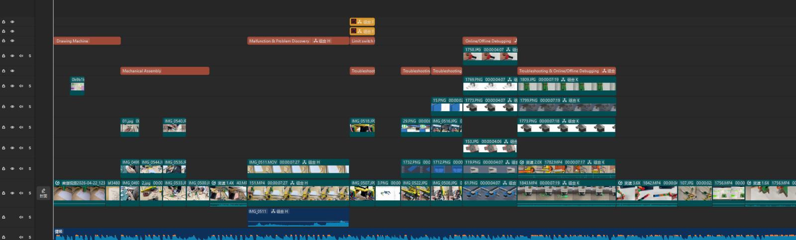
Figure: Video editing and media organization for the group machine documentation.
This part was important because a machine design assignment needs to show the machine movement, not only static images. The edited video helped explain the machine behavior and made the group documentation easier to understand.
Learning Workflow Reconstruction
After the group work, I reconstructed my learning process into the following workflow:
① Group Discussion and Idea Selection
I proposed a CPM machine idea, but the group did not select it after voting and discussion. The final direction moved toward a simpler and more feasible plotter-style machine.
② Modeling Follow-up and Structural Support
I followed the team’s model modification process and added small modeling support for the pen-holder frame support and the pen-clamping contact surface. The first part was about making the holder frame more stable, and the second part was about making the contact surface wider for better grip.
③ Media and Documentation Organization
I organized screenshots, photos, and videos to help explain the group machine process more clearly.
④ Personal Learning
I also used a small Mini CNC / plotter setup as personal learning. This helped me understand the basic machine-control workflow, including firmware upload, wiring, G-code generation, Candle setup, origin setting, and motion behavior.
The Mini CNC test was useful for my learning, but it was not the main group machine contribution. I record it as a personal learning test so that the group contribution and my own learning process are clearly separated.
Controller and Workflow Comparison
Analyzing Three Controller Paths in This Project
To understand the most suitable workflow for our team machine, I compared three paths that appeared in this project: the Arduino UNO group machine workflow, my Arduino Nano Mini CNC learning test, and the ESP32 future workflow.
| Platform / Workflow | Hardware / Setup | Role in This Project | Advantages | Suitable Stage |
|---|---|---|---|---|
| Arduino UNO Path | UNO + CNC Shield v3 + GRBL / G-code sender | Main workflow for the group drawing machine | Mature CNC workflow, clear debugging logic, easier for team synchronization | Current group machine |
| Arduino Nano Path | Nano + ULN2003 + 28BYJ-48, based on the Mini CNC setup I tested | Personal learning test to understand basic motion control | Simple structure, useful for understanding firmware, wiring, G-code, origin setting, and slow motor movement | Personal learning / early validation |
| ESP32 Future Path | ESP32-based controller, such as FluidNC | Future possibility, not used for the final group machine this week | More advanced control options and possible wireless / WebUI workflow | Future upgrade |
Summary: For this week, the Arduino UNO workflow was the most suitable path for the group machine because it gave the team a shared and stable technical language. The Arduino Nano Mini CNC test helped my personal understanding, but it was not the group machine workflow. ESP32 was kept as a future possibility.
Workflow Comparison: Stability vs. Complexity
In this project, I realized that choosing a controller is also choosing a debugging workflow.
1. Arduino UNO-based workflow — group machine path
① Mechanical assembly → ② UNO + CNC Shield / drivers → ③ GRBL / sender setup → ④ G-code test → ⑤ Tool-change and drawing test → ⑥ Iteration
This was the most suitable workflow for the group machine because it reduced debugging risk and made communication easier between online and offline members.
2. Arduino Nano-based Mini CNC workflow — personal learning path
① Software setup → ② Firmware upload → ③ Nano + ULN2003 wiring → ④ SVG / jscut → ⑤ Candle COM / baud / origin setup → ⑥ Slow-speed drawing test
This was my personal learning test. It helped me understand the full control pipeline from file preparation to physical movement. However, it should not be confused with the group machine workflow.
3. ESP32-based workflow — future path
① Controller selection → ② Pin mapping → ③ FluidNC / firmware configuration → ④ WebUI or network debugging → ⑤ Machine re-validation
ESP32 could be useful for future wireless or IoT-style control, but it would add extra configuration and debugging work. For a time-limited group machine project, this was not the safest path.
Summary of Differences
| Feature | Arduino UNO Group Workflow | Arduino Nano Mini CNC Test | ESP32 Future Workflow |
|---|---|---|---|
| Main purpose | Build and test the team machine | Personal motion-control learning | Future upgrade |
| Debugging style | Shared GRBL / sender workflow | Simple small-machine testing | Firmware + network configuration |
| Collaboration | Easy for team discussion | Useful for my own understanding | Harder during a short deadline |
| Risk level | Low / predictable | Low, but limited to learning | Higher setup complexity |
| Status this week | Adopted for group work | Personal learning test | Not used |
Conclusion: The group needed a stable shared workflow more than a more powerful controller. The Arduino UNO workflow supported the team machine, while the Nano Mini CNC test helped me understand the same type of motion-control logic at a smaller scale.
Reference Resources
| Resource | Role in my understanding | Link |
|---|---|---|
| Arduino Serial Monitor | Helped me understand serial debugging | Arduino Serial Monitor |
| Universal G-code Sender | Helped me understand the GRBL / G-code sender workflow | UGS Official Website |
| GRBL-servo | Helped me understand servo-based pen-lift logic | cprezzi/grbl-servo |
| FluidNC | Used only as a future ESP32-based reference | FluidNC Repository |
| Mini CNC Plotter Reference | Used as a small plotter reference, not as proof of the exact controller used in my borrowed setup | Thingiverse #4579436 |
Personal Learning Test: Mini CNC Workflow
Workflow Overview
Download Software ➡ Install IDE ➡ Hardware Wiring ➡ Upload Firmware ➡ jscut G-code Generation ➡ Candle Calibration ➡ Machine Running!
Software & Resources
| Software/File | Download Link | Purpose |
|---|---|---|
| Arduino IDE | arduino.cc | Burn firmware to Nano |
| GRBL-28byj-48 | GitHub | Modified firmware for 28BYJ-48 stepper motors |
| Candle | GitHub | G-code sender to control the machine |
| Inkscape 1.0.1 | Official Download | SVG Design (Stable version for plugins) |
| jscut (Web) | jscut.org | G-code Generator (Online tool) |
| Reference | PCBWay Tutorial | Complete build guide and documentation |
Hardware Wiring
Connect the ULN2003 driver to Arduino Nano as follows. Ensure the wiring matches the firmware pin definitions.
| Axis | Arduino Pins | ULN2003 Pins (IN4-IN1) |
|---|---|---|
| X Axis | D2, D3, D4, D5 | IN4, IN3, IN2, IN1 |
| Y Axis | A0, A1, A2, A3 | IN4, IN3, IN2, IN1 |
| Z Axis | D8, D9, D12, D13 | IN4, IN3, IN2, IN1 |
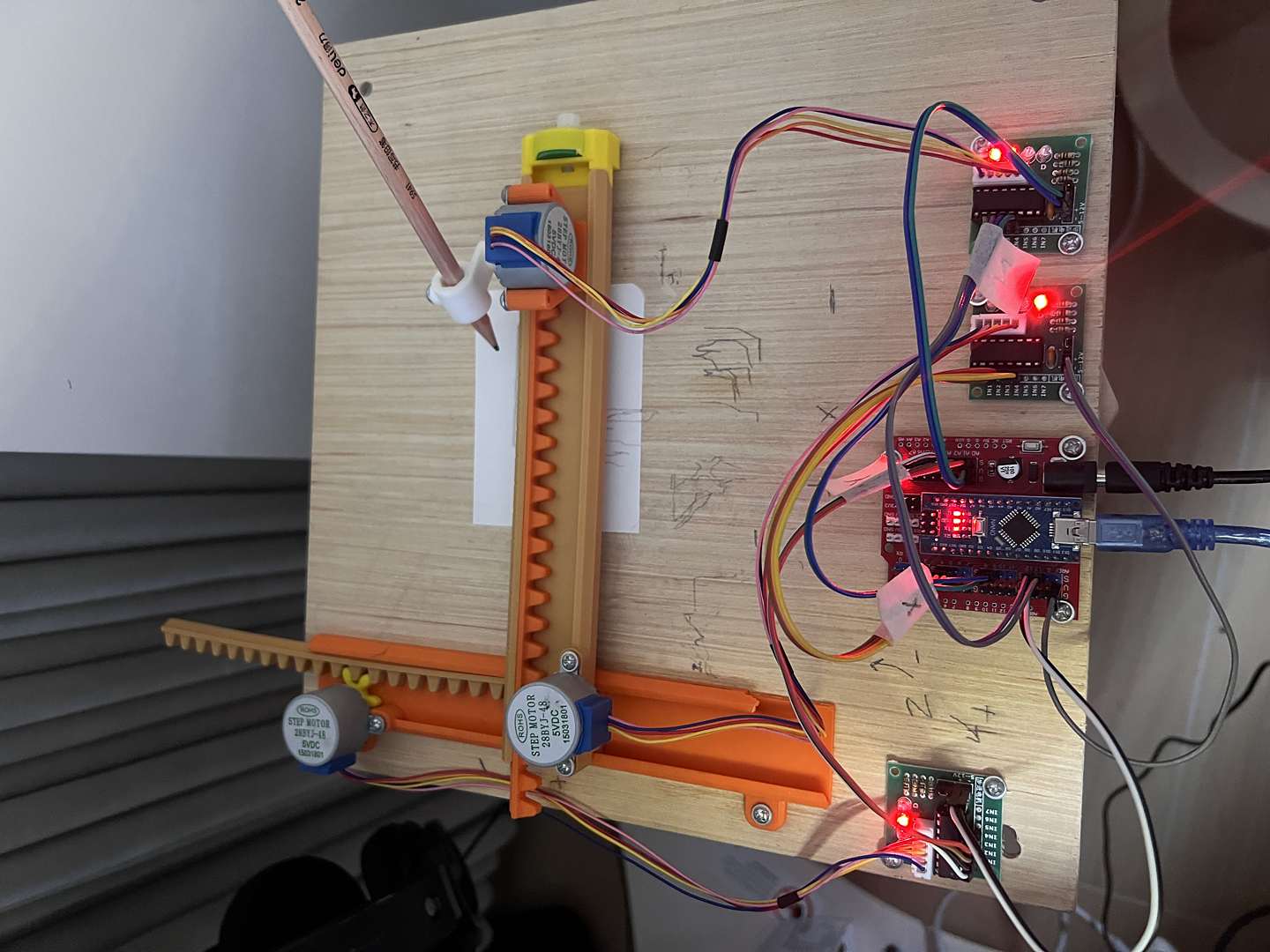
⚠️ Caution: ULN2003 VCC must connect to an external 5V power supply. Do not take power from the Nano's 5V pin to avoid insufficient current and potential damage.
Firmware Configuration
Arduino IDE Settings
| Menu Item | Selection | Description |
|---|---|---|
| Board | Arduino Nano |
⚠️ Must select Nano |
| Processor | ATmega328P (Old Bootloader) |
Required for most generic/clone Nano boards |
| Port | COMx |
Identify your Nano's specific port |
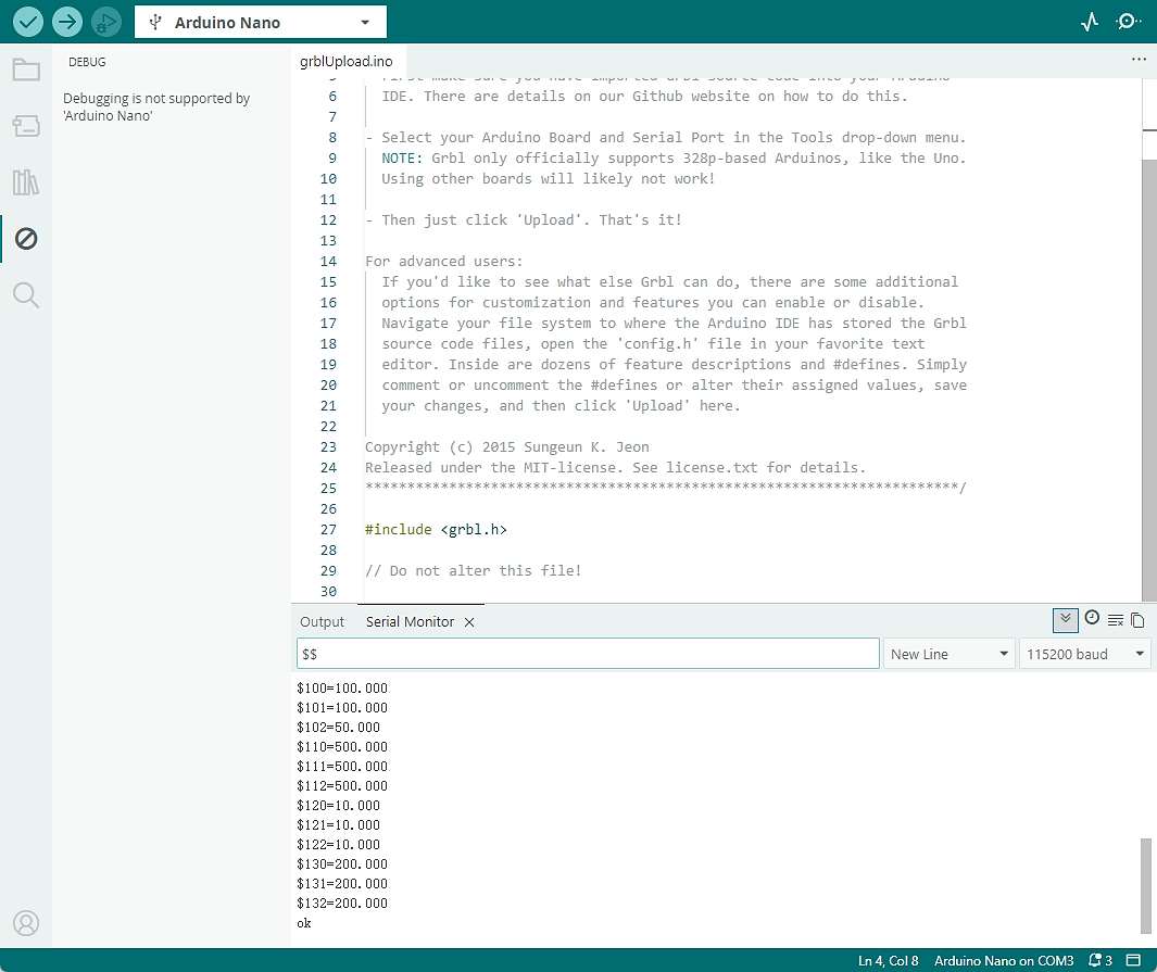
Upload & Verification
- Import the
grbllibrary into the Arduino IDE. - Open
File > Examples > grbl > grblUpload. - Click Upload (→). After "Done uploading", open the Serial Monitor (set to 115200 baud).
- Type
\$and press Enter. If a list of parameters appears, the firmware is running correctly.
Standard GRBL commonly uses 115200, but modified firmware such as GRBL-28byj-48 may use a different baud rate, so I should check the firmware documentation or config.h if connection fails.
G-code Generation (jscut.org)
Prepare SVG
Reuse Existing Assets: Instead of drawing from scratch, I used a pre-designed Logo SVG from my previous weekly assignments (e.g., Computer-Aided Design week). This allowed me to focus on the conversion and plotting accuracy. If you use new one, you can follow:
- Use Inkscape to draw or open graphics.
- Ensure the design size is within the machine's travel limits (e.g., < 80×80mm).
- Save the file as
.svg.
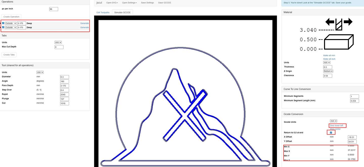
jscut Key Settings
- Import: Drag the SVG file into jscut.org.
- Operation: Select Outline (Do not use Pocket for pen plotters).
- Zero Point: Click "Zero lower left" in Gcode Conversion to ensure
Min X/Y = 0. - Speed Adjustment (For 28BYJ-48):
- Rapid: 500 (Travel speed)
- Cut: 300-500 (Drawing speed)
- Plunge: 100 (Z-lift speed)
Candle Operation
Connection & Origin
- Close the Arduino Serial Monitor first to free the COM port.
- In Candle, go to
Service, select the COM Port, and set Baud to 115200. - Use the Jog panel to move the pen to the paper's lower-left corner.
- Z-axis Handling: Lift the pen slightly (0.5-1mm above the paper) then set Z0. This prevents the pen from dragging during travel.
- Click X0, Y0, Z0 to zero all work coordinates.
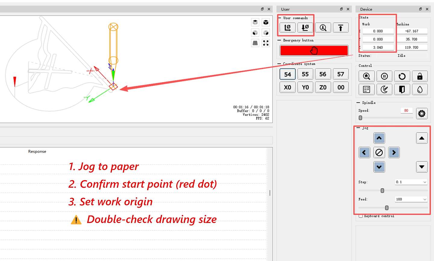 The Z value you see after drawing (like 3.04 mm) is the automatic lift height.
Speed & Run
- Set Feed rate and Rapid speed overrides to 20-30% in Candle.
- The 28BYJ-48 motor has low torque; running too fast will cause step loss.
- Click Send to start the job.
Troubleshooting
| Problem | Cause | Solution |
|---|---|---|
| Connection Failed | COM port occupied | Close Arduino IDE or Serial Monitor |
| Offset Drawing | Didn't zero in jscut | Click Zero lower left in jscut and re-export |
| Pen Not Lifting | Z-axis direction error | Check Z Origin/Clearance settings in jscut |
| Motor Stalling | Speed too high | Reduce speed to 20-30% and check external power |
Core Summary
- SVG Size ➡ Must be smaller than machine travel.
- Zero Lower Left ➡ Critical to avoid coordinate offset.
- Slow Speed ➡ Essential for the low-torque 28BYJ-48 motors.
- Close Serial Monitor ➡ Otherwise, Candle cannot access the COM port.
- Zeroing before Send ➡ Always set X0 Y0 Z0 at the physical starting point.
Reflection: What I Learned
The Challenge of Remote Collaboration
This was my first time doing such intense remote teamwork. I learned that there is always a gap between a digital model and a physical object. I realized that organizing media in real-time is a lifesaver—sorting photos as you go makes communication faster and saves hours when it's time to edit the final video.
Personal Trial: Lessons from the Mini CNC
By running the Mini CNC myself, I ran into the same "hidden hurdles" the team faced, which helped me understand the project much more deeply:
-
Lack of Rigidity: The Mini CNC frame was a bit shaky. I learned that you can't always fix hardware with more hardware—sometimes you just have to slow down the speed (to 20-30%) in the software to get a steady line.
-
The Z-Axis Struggle: I finally understood why Yaro spent so much time on the Z-axis. Getting the pen to touch the paper "just right"—not too high to miss and not too low to drag or stall the motor—is a delicate balancing act that requires a lot of patience.
-
SVG Scaling & Origins: I also struggled with drawings being offset or the wrong size. I found that jscut is great because you can see the exact dimensions on the screen. Clicking "Zero lower left" was the "magic button" to fix the origin issues. Because I had seen the team struggle with this before, I was able to find the fix much faster during my own trial.
Reflection: What I Learned from the Personal Test
The Mini CNC test helped me understand several practical issues in machine control:
- A weak or flexible frame can affect drawing stability.
- The pen height and Z-axis setting are important because the pen must touch the paper without dragging too hard.
- SVG scale and origin settings directly affect the drawing position.
- Low-torque motors need slower speed settings.
- Serial connection problems may come from COM port occupation or baud-rate mismatch.
This personal test helped me understand the machine behavior more clearly, but my main group contribution remained communication, modeling follow-up, media organization, and documentation support.