05 3D scanning and printing
Assignments
Group Assignment
- Test the design rules for your 3D printer(s).
- Document your work on the group work page and reflect on your individual page what you learned about characteristics of your printer(s).
Individual Assignment
- Design, document and 3D print an object (small, few cm3, limited by printer time) that could not be easily made subtractively.
- 3D scan an object (and optionally print it).
Learning Outcomes
- Identify the advantages and limitations of 3D printing.
- Apply design methods and production processes to show your understanding of 3D printing.
- Demonstrate how scanning technology can be used to digitize object(s).
Group Assignment
PETG Comprehensive Performance Test Report
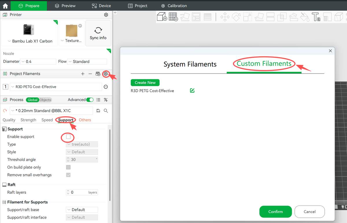
Date: 2026-01-29 Device: Bambu Lab X1 Carbon (0.4mm Nozzle) Material: R3D PETG (Standard Profile, Layer: 0.20mm) Key Settings: Support Disabled Key Settings: Support Disabled — To test the raw capabilities and limits of the machine.
I put the test pieces on a plate for printing, so the characteristics of the material are that some fried noodles appear, but it does not completely affect the test results.
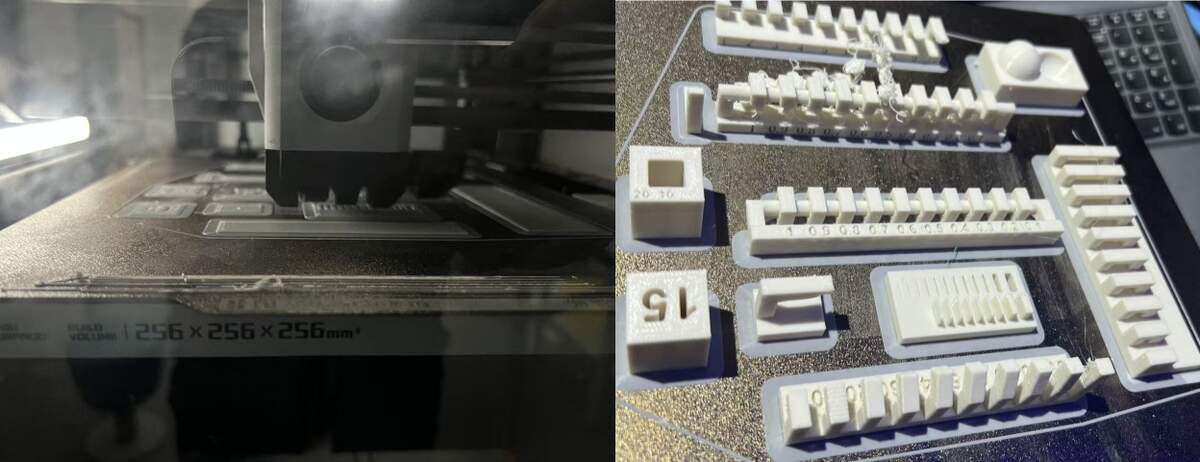
Component Analysis
- 1.0-90° Overhang Angle & Cantilever Capabilities
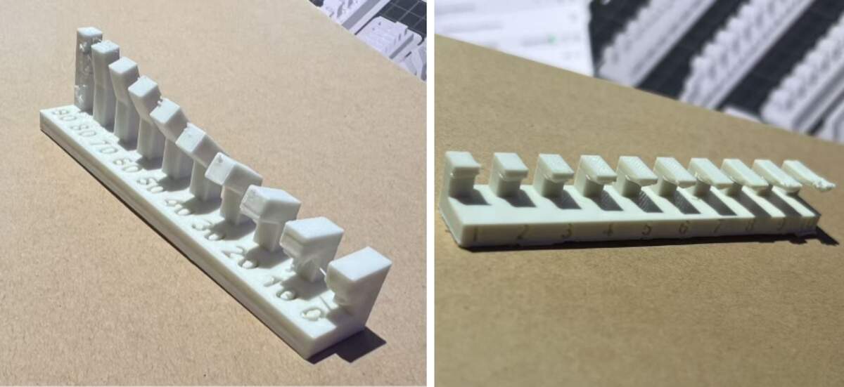
Purpose: Evaluate gravity resistance (Gradual Angle vs. Horizontal Cantilever), and determine the starting angle from which good print quality can be achieved without supports (i.e., the self-supporting threshold).
- < 40° (Supports Required):
- Observation: Angles below 40° require supports. In this range, the material cannot withstand gravity, resulting in severe drooping and structural failure.
- ≥ 40° ( No Supports Needed):
- Observation: Good performance starts from 40°.* In this range, good surface and structure can be achieved without supports* (Note: Extreme angles like 90° may be slightly rough due to heat creep, but the structure remains intact).
90° Horizontal Cantilever
- Observation: Immediate drooping/failure regardless of length.
- Conclusion: Must use supports for any horizontal cantilever.
- Bridging
Purpose: Verify the material's bridging capability over suspended spans.
Conclusion: Horizontal bridging within 20mm is a safe zone and can be printed directly without supports.
-
Curved Surface & Fine Detail
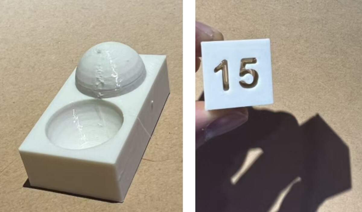
Purpose: Evaluate the printer's ability to handle curved surfaces (stair-stepping effect) and the definition of small internal hollow text (negative space).
- Hemisphere vs. Concave Surface:
- Observation: Comparing the convex dome and the concave bowl, the concave effect is significantly better than the convex dome construction.
- Convex Dome:* 0.2mm layer height causes visible stair-stepping* on the top curvature, resulting in a rough texture.
- Concave Surface: The internal curve transition is more natural, and layer lines are visually less prominent than on the convex surface, resulting in higher surface quality.
- Observation: Comparing the convex dome and the concave bowl, the concave effect is significantly better than the convex dome construction.
- Recessed Text "15":
- Observation: The number outlines are clear with sharp edges. This indicates good retraction control when handling fine negative space, with no blurring caused by stringing or over-extrusion.
Conclusion: Excellent at handling fine recessed details; concave surfaces print better than convex ones; convex surfaces are limited by layer height physics with visible stair-stepping.
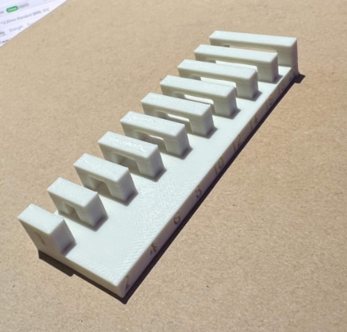
- dynamic moving parts & Static Comb *parts*
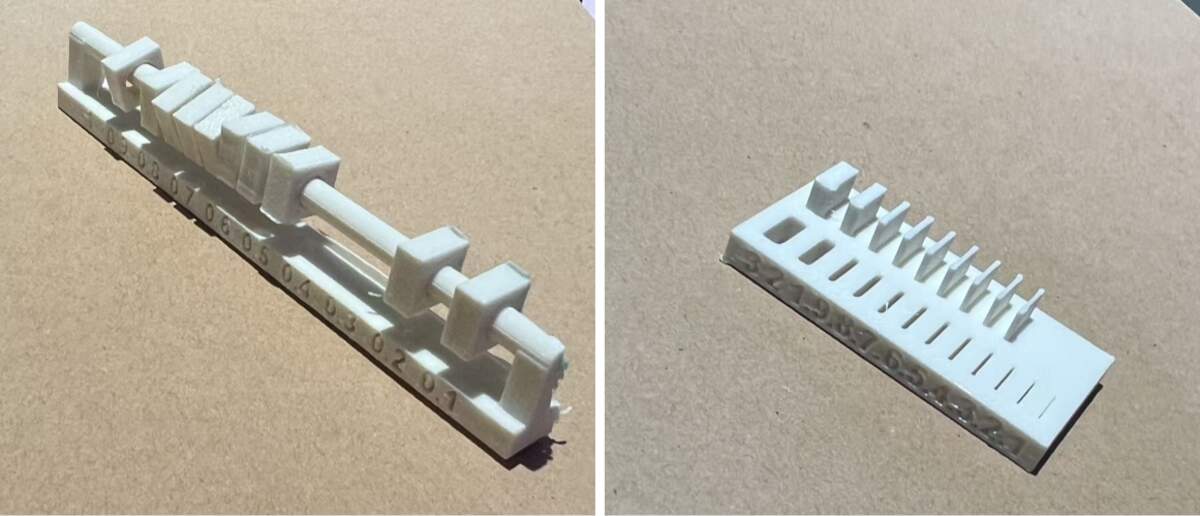
Purpose: Comprehensively evaluate tolerance requirements for dynamic moving parts (slider) and static mating parts (comb interlock), as well as the effect of material thickness on physical properties.
- Dynamic Slider Test:
- Observation:
- 0.1mm: Stuck
- 0.2mm: Tight Fit
- >0.2mm: Smooth
- Observation:
- Static Comb Test - Wall Thickness & Slot Width:
- Wall Thickness & Toughness:
- >1.0mm: Rigid
- <0.6mm: Flexible/Tough
- Observation: >1.0mm is rigid; <0.6mm becomes flexible/soft, showing PETG's toughness.
- Slot Width & Tolerance:
- Observation: When printing internal slots, there is a significant discrepancy between the design value and the actual measured width. Due to PETG shrinkage and extrusion expansion, the actual slot is often much narrower than designed.
- Conclusion:
- Maximize Slot Width
- Maximize slot width in design.* A mere 0.3mm margin might result in a tight fit or failure to insert. It is recommended to allow more generous clearance (e.g., 0.4mm or more)* or apply negative dimension compensation for holes/slots in the slicer.
- Wall Thickness & Toughness:
-
Dimensional Accuracy & Wall Deviation
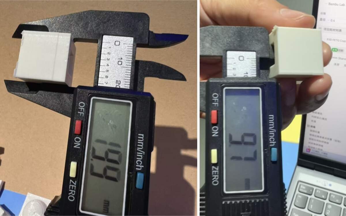
Purpose: Quantify the error difference between outer walls and inner holes.
- Outer Wall:
- Measured 19.9mm (Error 0.1mm); Normal.
- Inner Hole:
- Measured 9.7mm (Error 0.3mm); Significant inner shrinkage.
- Conclusion & Material Analysis:
- Inner hole error is 3x that of outer walls.
- Impact of PETG Characteristics:
- PETG's high viscosity causes a dragging effect inward when printing small circles, exacerbating shrinkage.
- Correlation with dynamic moving parts & Static Comb parts :
- This data confirms the "narrowed slot" phenomenon in dynamic moving parts & Static Comb parts . Slots are also "internal features" affected by dragging/shrinkage, making a 0.3mm design gap effectively <0.1mm.
-
Design Guide*: Compensate internal holes/slots by +0.3mm*.
-
Test file: 3Dtest
Individual Assignment
Design, document and 3D print an object
For my personal 3D assignment, I directly used my Computer-Aided Design week model Link here. It was designed with actual dimensions and very suitable for 3D printing.
File: halfmodel
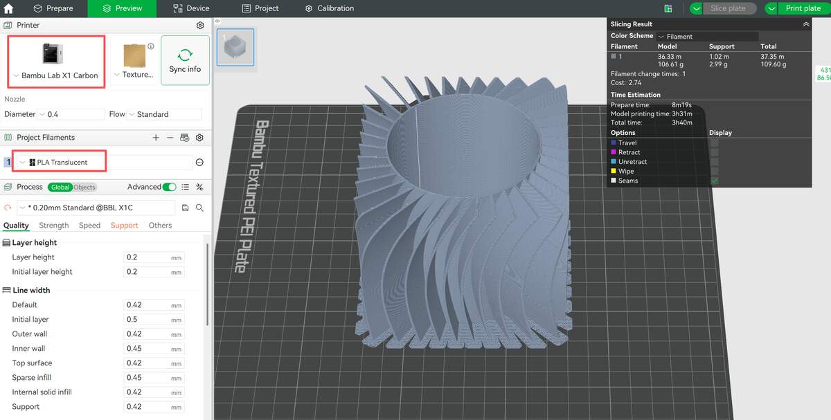
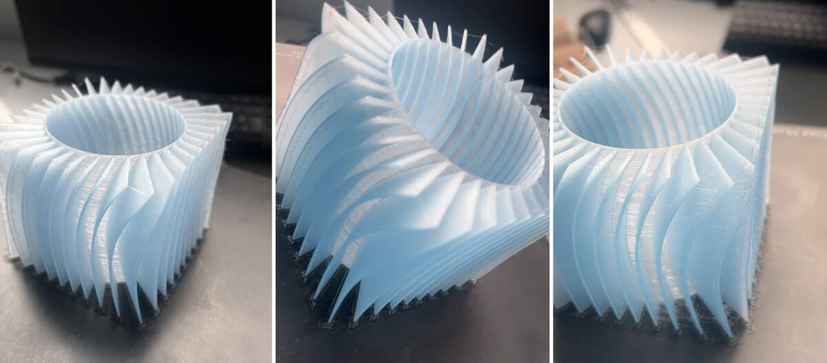
The model features a dense array of thin, twisted blade-like structures integrated with a hollow cylindrical core and square base—geometry that would be extremely difficult, if not impossible, to produce subtractively (e.g., via CNC milling or carving) due to the narrow internal spaces, delicate thin walls, and complex curved surfaces that cannot be accessed or shaped with traditional cutting tools. In Bambu Studio, I selected the matching equipment and material, and cut the model to shorten printing time. With previous tests, the whole printing process went smoothly.
Process
- File Preparation: I used my earlier Fusion 360 file with real-scale dimensions, which was ready for 3D printing.
- Equipment & Material: In Bambu Studio, I chose Bambu Lab X1C and its matching transparent filament.
- Parameter Settings: I did not make extra parameter adjustments. I followed the official settings for the branded filament, and this setup ensured a successful print.
- Preparation Check: The test and this assignment were done on consecutive days, so the machine and material were confirmed to be in good condition.
Result & Reflection
The print finished successfully and matched the design size and details well. The transparent filament gave a clear visual result.However, two issues appeared:
- Stringing
- Bulges at retraction points
Core Optimization Idea
Optimize the full closed loop:
Extrusion — Retraction — Travel — Re-extrusion
Optimization Plan
- Improve Retraction
- Retraction distance: 1.5–2.5 mm
- Retraction speed: 40–60 mm/s
- Enable Wipe on Retraction and Z-axis Lift to reduce buildup and scratching.
- Optimize Travel Movement
- Travel speed: 150–200 mm/s
- Keep travel paths inside the model, avoid crossing thin walls.
- Adjust Temperature
- Lower nozzle temperature by 5–10°C to reduce material oozing.
- Change Printing Order
- Switch from layer-by-layer to object-by-object to reduce extrusion-retraction cycles.
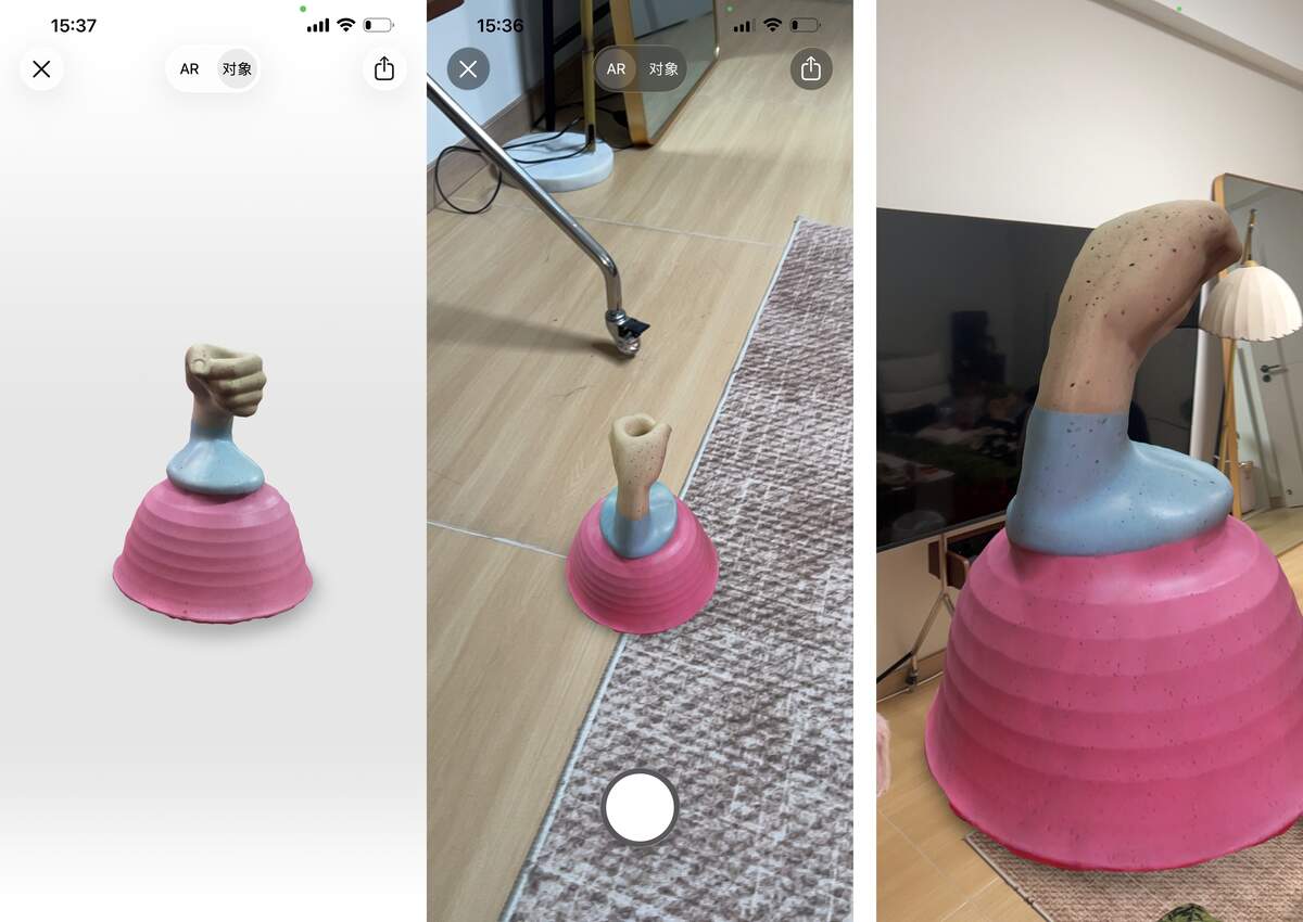
3D scan
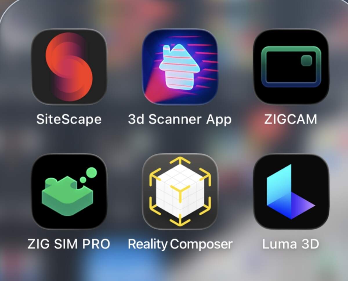
As an iOS user, I have tried many 3D scanning apps, and finally chose Reality Composer. This app is very convenient and does not require complicated procedures. I have sorted out the detailed operation workflow and reflections.
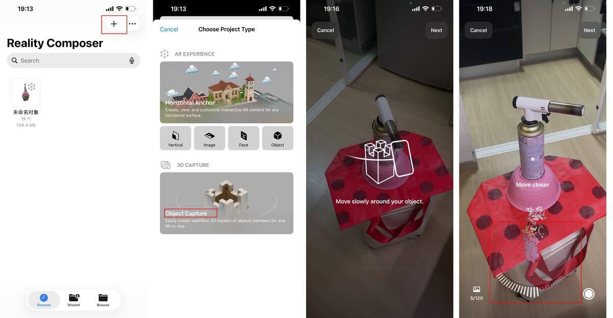
- Create a Project: After launching the app, tap the “+” icon in the top-right corner to create a new object scanning project.
- Select and Frame: In the scanning interface, select the center point of the target object and adjust the recognition frame to enclose the object you want to scan.
- Start Scanning: Once scanning starts, the number of images to be captured is displayed at the bottom of the screen, along with real-time feedback on whether each angle was captured successfully.
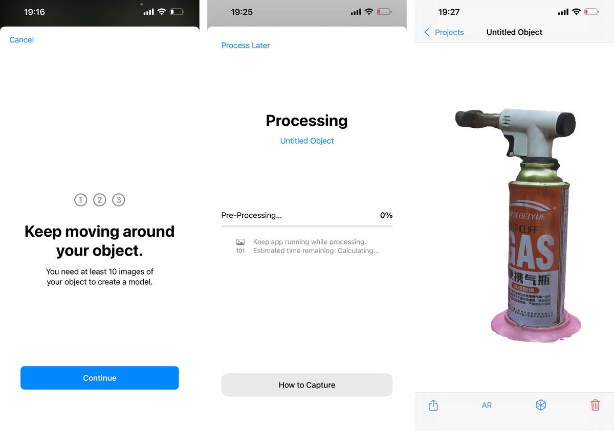
- Change Angles: After completing a full 360° scan, the app will prompt you to flip the object and change the shooting angle, which you can do as needed.
- Generate Results: After capturing images from 3 different angles, wait for the processing to finish, and the final 3D scan result will be ready for display.
Key Learnings & Reflections
The initial scan results were less than ideal due to the reflective material of the object, so I conducted additional tests. This experience highlighted the critical importance of an object’s material reflectivity and ambient lighting on scan quality.
Later, I scanned objects made of less reflective materials, and successfully used 3D scanning technology to digitize physical objects—turning real items into editable digital 3D models inside the app.
The scanned models can be displayed in AR mode, which is really fun—you can scale the model up to a large size in the room and even take photos with it! Due to current space constraints, this is the best result I could achieve for now.
Moving forward, I will be more rigorous in selecting scanning environments and carefully account for material reflectivity to obtain higher-quality scans, and further integrate these digitized models into my 3D design workflow.
Reflection
I have learned that it is essential to understand the materials and 3D printers in advance—different machines come with different issues, and this field really relies on practical experience. That said, modern equipment has become extremely user-friendly overall. In the future, I plan to learn more about the process of building DIY 3D printers.
3D scanning devices and apps are also becoming easier to use. Previously, I focused more on scanning spaces, turning them into particle systems, and importing them into Touch Designer to create interactive works: camera movement in space, particle animation, and dynamic material changes were my typical workflow.
One more key takeaway is that keeping printing materials dry is critically important—moisture directly affects the final print quality and can easily cause defects.