Computer-Aided Design
Assignment
- Evaluate and select 2D and 3D software
- Demonstrate and describe processes used in modelling with 2D and 3D softwares
- Demonstrate image and video compression
Overview: Developed automated scripts using FFmpeg and ImageMagick to streamline batch processing of media for efficient documentation. Software Evaluation: I’ve adopted Fusion 360 for parametric modeling, using Adobe Illustrator as a vital intermediary. By refining paths in AI and exporting them as SVG files, I’ve resolved curve compatibility issues and path fragmentation, ensuring seamless output for laser cutting. Project Progression: I am mastering Fusion's logic through iterative projects, including parametric lamps, interlocking snowflakes, and laser-cut trees. These exercises build the technical foundation for my Final Project—a Smart Meditation Chair—focusing on integrating intelligent modules into an organic, curved structure through a refined parametric-to-SVG workflow.
2D and 3D software
LaserMaker
In practical laser cutting operations, determining material parameters is the most frequent and critical task. The latest version of LaserMaker (v2.1.7.2) excels by integrating the "Material Testing Matrix" as a highly automated feature, which drastically streamlines the preparation process.
Limitations of Native Tools
While LaserMaker is efficient for parameter testing, its node-level editing (Vector Manipulation) is limited. For my personalized surname logo "S", the freedom of anchor editing was insufficient, necessitating the switch to Adobe Illustrator.
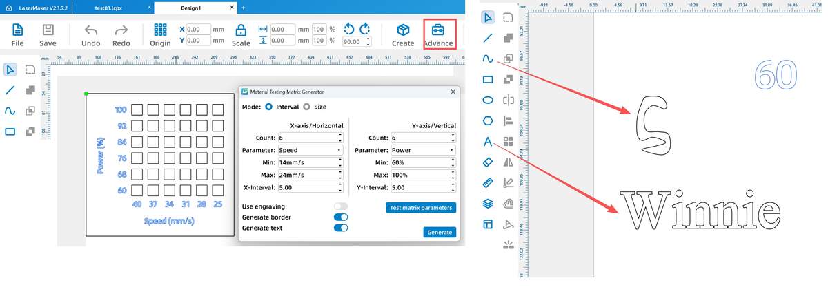
One-Click Generation of Automated Testing Matrix
Quickly establishing a power vs. speed comparison matrix using the "Advance" tool in LaserMaker.
Adobe Illustrator (Win)
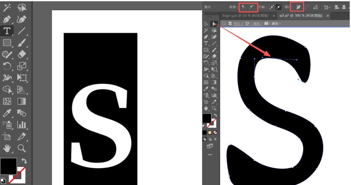
To transform the letter "S" into a unique, customized logo, I utilized AI 2021 to perform detailed path operations.
Core Workflow: From Font to Customized Shape
I summarized an efficient vector editing process using the following "Arrow-Flow" steps:
Step 1: Text Preparation
Type Tool (T) ➡ Input S ➡ Select bold font (e.g., Arial Black) ➡ Ctrl + C (Backup original).
Step 2: Create Outlines (Vectorization)
Select text ➡ Ctrl + Shift + O ➡ Convert text object to "Vector Paths" ➡ Dense anchor points appear along the edges.
Step 3: Anchor Manipulation
Direct Selection Tool (A) ➡ Click specific anchors ➡ Drag position (shape deformation) ➡ Adjust Handles (curvature control) ➡ Refining the "S" to be smoother/sharper.
Step 4: Path Optimization
Pen Tool (P) (Add/Delete anchors) ➡ Shift + C (Toggle Corner/Smooth) ➡ Object -> Path -> Simplify (Clean up redundant nodes for smoother machining).
Step 5: Exporting
Select design ➡ File -> Export Selection ➡ Choose SVG format ➡ Save.
Optimizing the curves of the "S" by adjusting anchor handles in AI.
Using the Direct Selection Tool to perform significant deformation on local paths.
⚠️ Issue: DXF Path Fragmentation
DXF exports often break closed curves into disconnected segments. This causes the machine head to lift/drop repeatedly, wasting time and ruining edge quality.
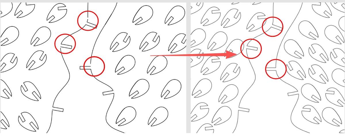 Comparison: Fragmented paths in DXF (left) vs. continuous SVG paths (right).
Solution: SVG for Lossless Transfer
SVG (Scalable Vector Graphics) proved to be the most stable bridge:
-
Preserve Integrity: SVGs keep "Closed Path" attributes intact.
-
Ready to Process: Paths remain continuous in LaserMaker, requiring no manual repair.
B&W Graphic Pre-processing & CAM Logic (All-in-One)
To minimize repetitive settings in machine control software (CAM), I use a unified logic for Color Filling and Stroke Extraction as illustrated below. For instance, starting with my customized black-filled "S":
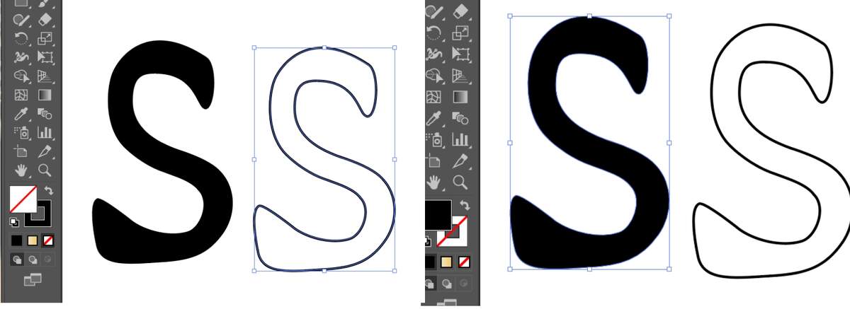
- Switching to Stroke (Cutting):
Select the black "S" ➡ Press Shift + X (Instantly swap Fill and Stroke) ➡ The solid "S" becomes a hollow outline.
- Refining for Precision:
Select the outline ➡ Set Stroke color to different colors (e.g., Red or Blue) to distinguish between different processes ➡ Set Stroke Weight to 0.01 mm (or 0.1 pt) for high-precision cutting.
Reflection:
Adobe Illustrator is more than just a creative drawing tool; in the context of digital fabrication, it serves as a critical bridge between design and production.
-
Problem Solver: Many "small issues" encountered in CAM software, such as path fragmentation or incompatible file headers, can be efficiently resolved in AI by re-exporting through stable formats like SVG.
-
Precision Control: Through direct manipulation of anchor points and stroke weights, AI allows for a level of precision that basic machine software often lacks. It is my primary tool for "cleaning up" designs before they ever touch the machine.
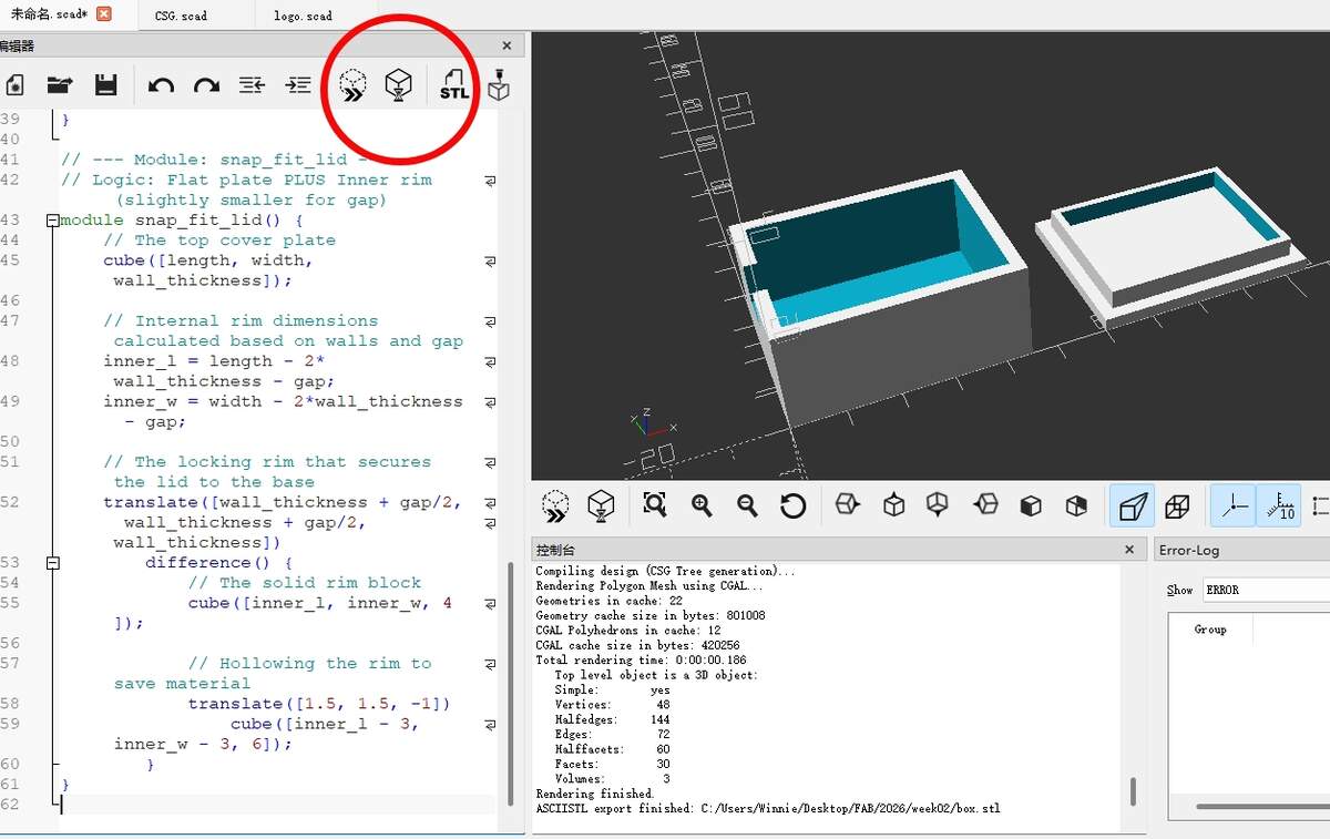
OpenSCAD
The OpenSCAD workflow revolves around a cycle of coding and previewing. Mastering these shortcuts is essential for an efficient design process:
-
F5 (Preview): Performs a quick "Z-buffer" preview. It’s the primary way to see changes instantly as you code.
-
F6 (Render): Calculates the full CGAL geometry. This is a "heavy" operation required before exporting to STL.
-
F12 (Highlight Subtractions): Useful for debugging. It highlights the "negative space" created by the
#modifier.
Parametric Methodology: The Sensor Enclosure
To learn the fundamentals, I designed a parametric enclosure. The goal was to create a modular system where the box, the lid, and the cable outlets automatically adjust when the base dimensions are changed.
Design Logic: Constructive Solid Geometry (CSG)
The core logic used here is CSG Subtraction. By using the difference() function, we take a solid block and subtract a smaller block from its center to create the hollow interior.
Modular Scripting
I separated the design into two distinct modules: base_housing and snap_fit_lid. This allows the AI and the user to modify specific parts of the assembly without affecting the rest of the code.
// ==========================================

// PARAMETERS

// ==========================================

// Define variables here for easy global modification

length = 45;

width = 35;

height = 20;

wall_thickness = 2.5;

gap = 0.25;        // Clearance tolerance for 3D printing fitment

// ==========================================

// EXECUTION

// ==========================================

// Display the assembly side-by-side

base_housing();

translate([length + 15, 0, 0])

    snap_fit_lid();

// ==========================================

// MODULES

// ==========================================

// --- Module: base_housing ---

// Logic: Solid box MINUS Inner box MINUS Side slot

module base_housing() {

    difference() {

        // Main outer body

        cube([length, width, height]);


        // Internal hollow space (translated to leave wall thickness)

        translate([wall_thickness, wall_thickness, wall_thickness])

            cube([length - 2*wall_thickness, width - 2*wall_thickness, height]);


        // Wire outlet: A small cutout on the side for cables

        translate([-1, width/2 - 4, height - 8])

            cube([wall_thickness + 2, 8, 10]);

    }

}

// --- Module: snap_fit_lid ---

// Logic: Flat plate PLUS Inner rim (slightly smaller for gap)

module snap_fit_lid() {

    // The top cover plate

    cube([length, width, wall_thickness]);


    // Internal rim dimensions calculated based on walls and gap

    inner_l = length - 2*wall_thickness - gap;

    inner_w = width - 2*wall_thickness - gap;


    // The locking rim that secures the lid to the base

    translate([wall_thickness + gap/2, wall_thickness + gap/2, wall_thickness])

        difference() {

            // The solid rim block

            cube([inner_l, inner_w, 4]);


            // Hollowing the rim to save material

            translate([1.5, 1.5, -1])

                cube([inner_l - 3, inner_w - 3, 6]);

        }

}
Learning Reflections
By leveraging AI-ready parametric code in OpenSCAD, I can efficiently manage manufacturing tolerances via "gap" variables and focus on the design of functional mechanical parts such as connectors and enclosures for my potential final project.
Fusion 360
I am focusing on Fusion 360 for its superior assembly logic and interference check capabilities, which prevent manufacturing errors at the digital stage. Its integrated ECAD environment is also a game-changer for the hardware-software integration of my Smart Meditation Chair. Project Milestones: I’m currently mastering the Sketch-to-Body workflow through iterative exercises like parametric lamps, interlocking snowflakes, and laser-cut trees. There show lamp processing. And you can also search How to Design A Wavy 3D-Printed Lamp in Fusion 360 directly on YouTube.
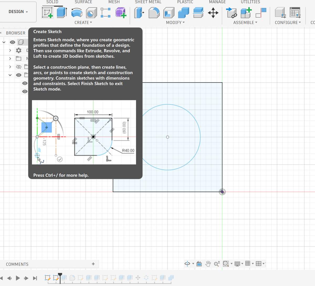
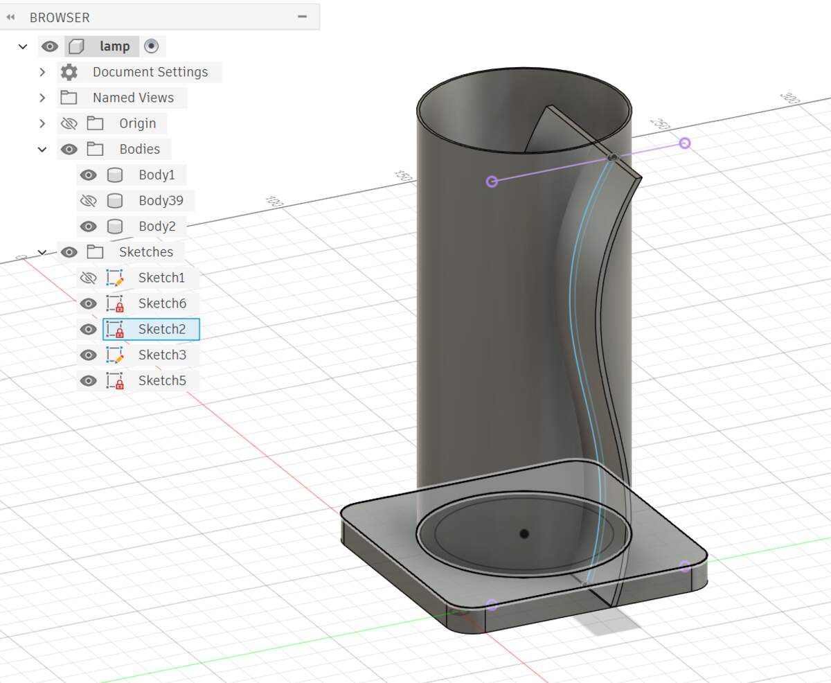
First of all, if you want to draw sketch, you need to create sketch to select a plane and then draw specifically.
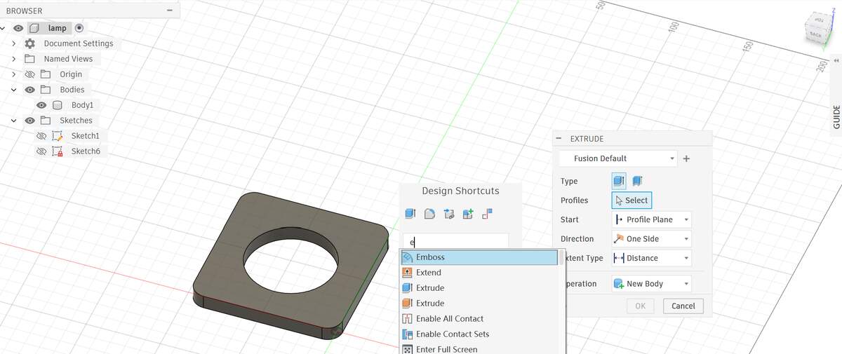
S - Search / Shortcuts: The Command Palette. It not only searches for commands but allows you to Pin frequently used tools (like Split Body) to this panel. This is the most important key.
View Ops
- Orbit:
Shift+Middle Mouse Button - Pan:
Middle Mouse Button - Zoom Fit (Find Lost Model):
Double Click Middle Mouse Button - Visibility:
V(Unlike Rhino's Hide, this toggles the "Lightbulb" icon on/off).
Sketching (2D)
L / R / C - Line / Rectangle / Circle: Intuitive; first letter corresponds to the command.
T - Trim: Scissors tool (Equivalent to TR in CAD).
O - Offset: Offsets lines or curves.
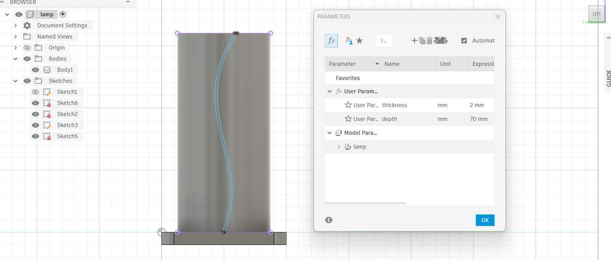
Here you can use parametrization to adjust the thickness and extrusion depth of the decorative lines of the lamp in real time. Note: To enter the new sketch hierarchy, select the correct view to draw the basemap.
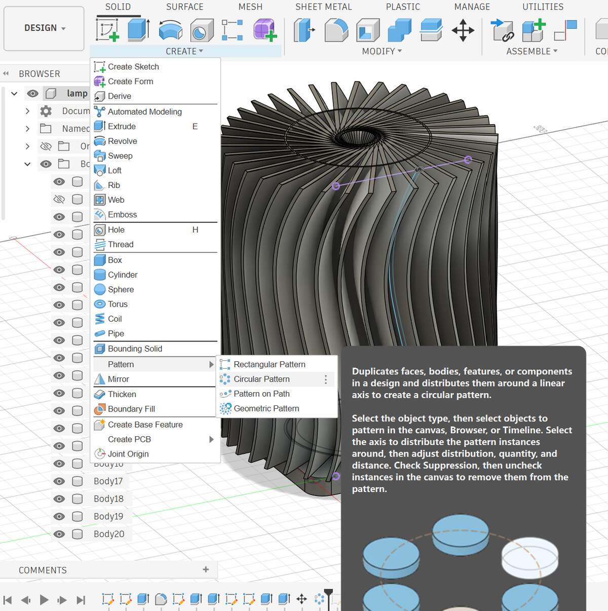
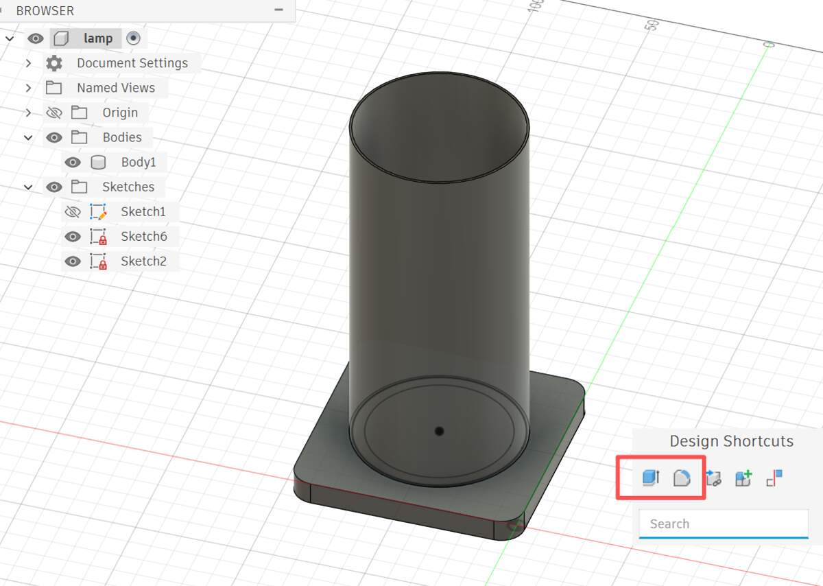
Use the Circular Pattern to quickly generate the overall shape of a single blade along the central axis. In this way, Feature Linked is established - this means that I only need to modify the original blade, and the blade of this whole circle will be automatically modified synchronously, which is very suitable for parametric luminaire designs that need to be debugged repeatedly.
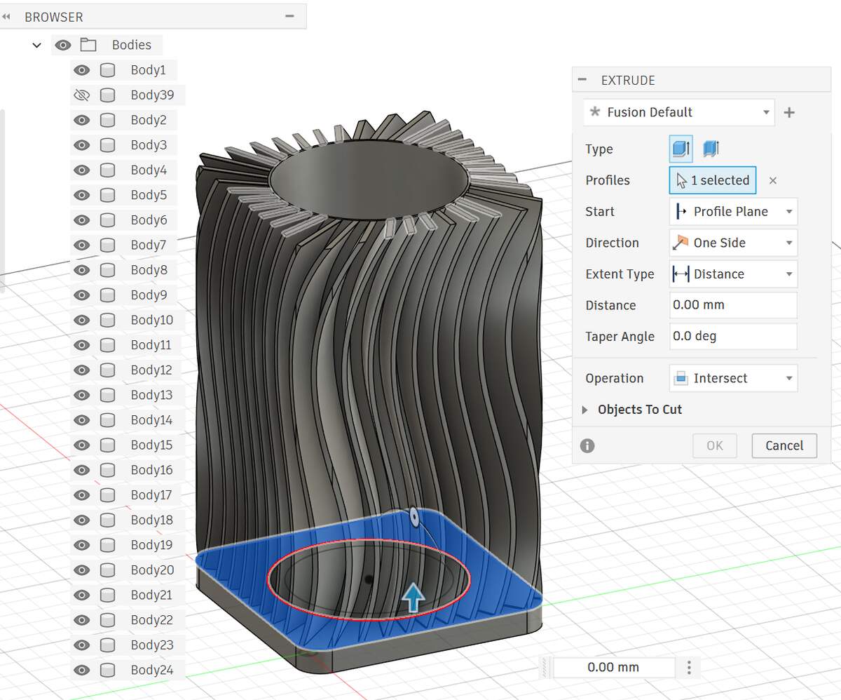
Select the base and use the Extrude-Intersect command to trim the original rough circular array to a clean cylindrical shape.
Demonstrate image and video compression
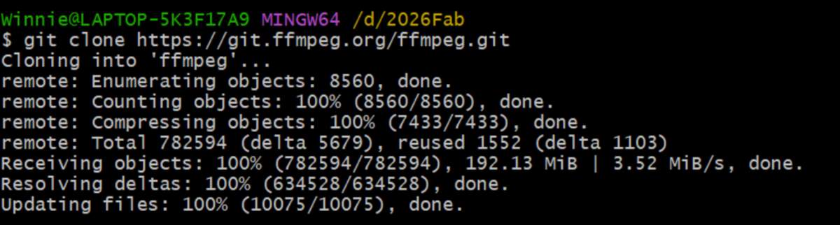
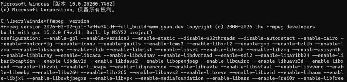
ffmeg
Installation - Check if the installation is successful - Add the local path to the exact location of the call

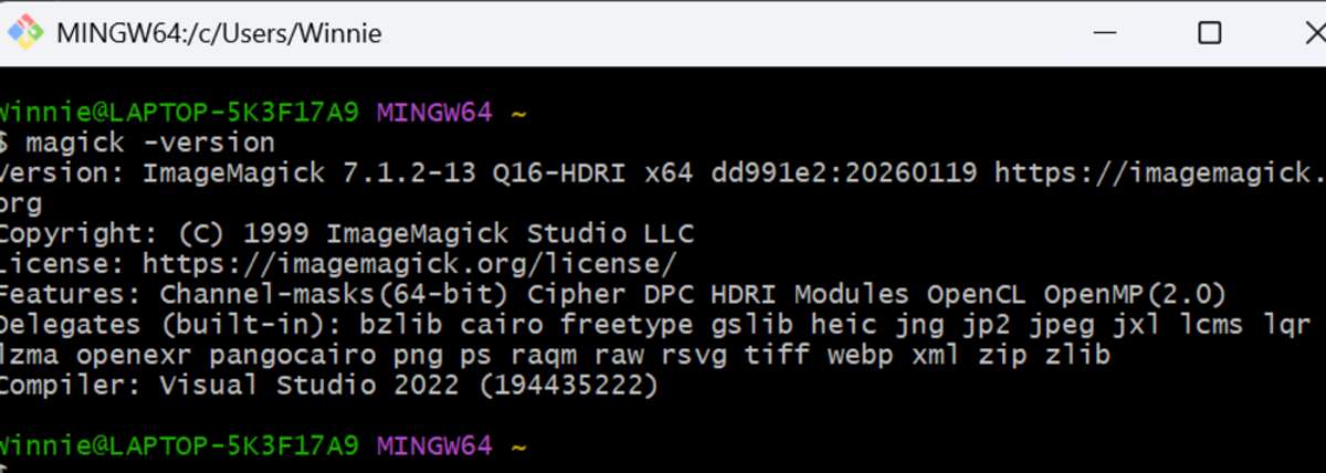
ImageMagick
It is recommended to download the local full.7z on the official website. Select Join path. Then check if the installation was successful. Once successful, it can be called from the command line.
I asked ai to help me write the .bat file to perform the compression work, the specific code is as follows:
Compression Results
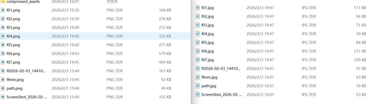
The size reduction is very considerable, some can be four times different.
squoosh Online Image Compression Tool
It works, but it’s not convenient for batch resizing. If there are individual images that need extra re-compression, you can use it for that. The page visualization is well-done.