
Week 15: System Integration
Assignment
- Design and document the system integration for your final project
This week, I mainly worked on my final project PCB and on designing the enclosure of my backpack.
Final Project PCB
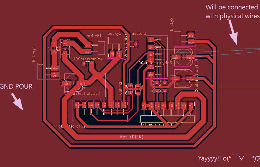
This is the complete schematic design!
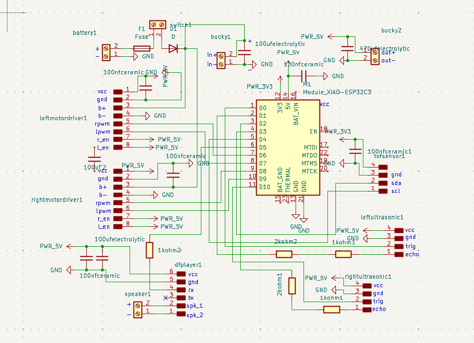
I referred to Mr. Théo Gautier’s Fab Academy site (thank you! 😄) and got the idea of designing a separate board for the motors. This made the routing process much easier and faster (It honestly would've taken me hours otherwise 🫠), and it was more practical for handling the different motor trace requirements.
To do that, I added two 6 pinheaders and connected one with the motor pins and the other with the XIAO ESP32 C3 pins. The two connectors will then be connected using jumper wires. In my PCB editor, I then separated the components. Note: I also added a GND pour and more details can be found on my Final Project Page.
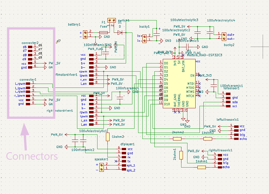
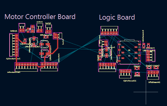
Here is the final look of the two boards! 😄
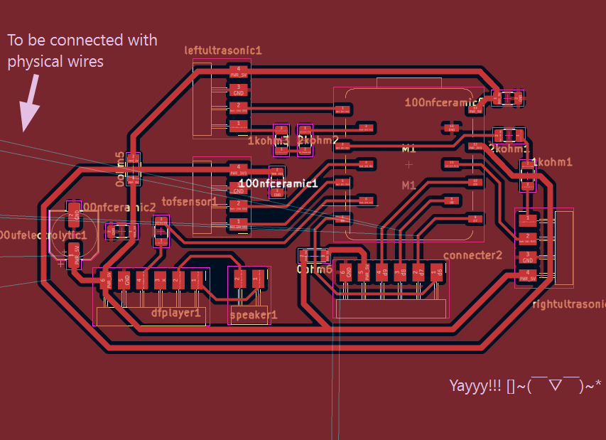
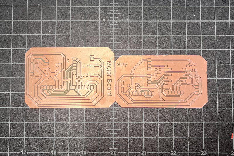
I milled out both the two boards. 😄
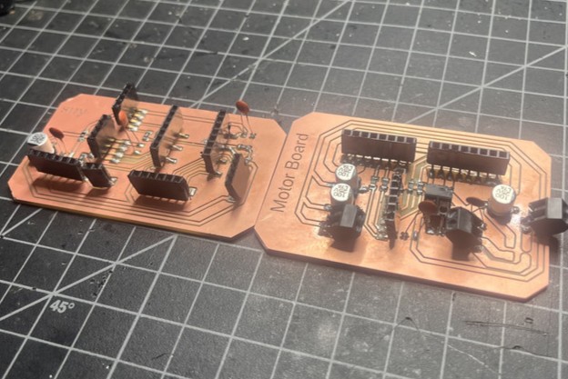
I then soldered the available lab components onto both the logic board and the motor controller board.
Exterior Design
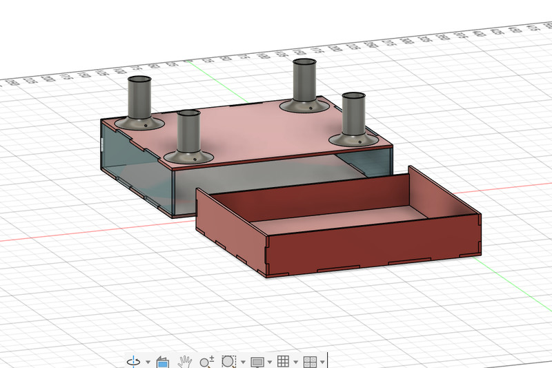
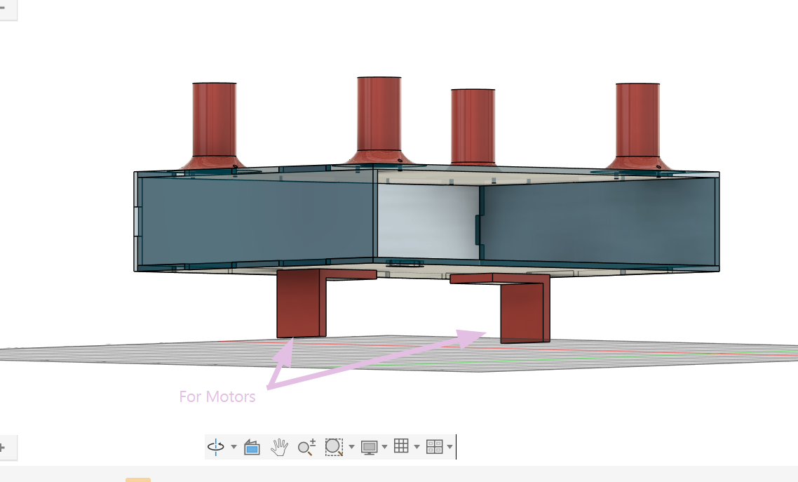
I made the first draft of my backpack's frame in Fusion 360
My initial plan was to use the CNC Machine for the outer box but now that I think about it, I feel like it will be a little too heavy so now, I plan to make use of the lasercutter for the entire base.
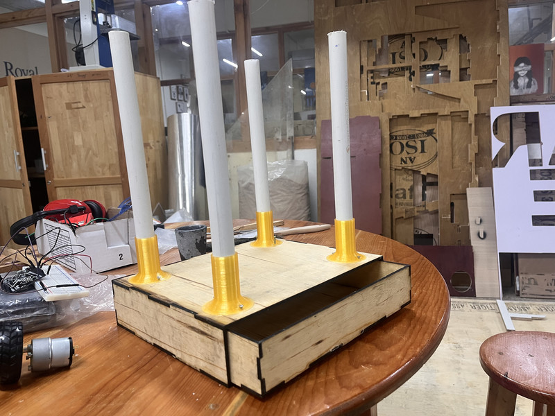
I also designed these PVC pipe holders that will be attached onto the frame. Sadly, I wasn't able to 3D print them becasue none of the 3D printers in our lab were functioning. 😕
As for the motor mounts, I'm thinking of an L-shaped structure. But since I don't have the motors right now, I'm not really sure of the exact dimensions. 🧐
After 3D printing the PVC holders and lasercutting the base, here is how it looks now! ☺️🥳 All my electronic components (excluding the sensors that will be mounted on the frame) will be placed inside the drawer. I will position one sensor in the center and place the other two on either side, each angled at 45°. I am planning to route the wires through the PVC pipes to keep them concealed while connecting the sensors.
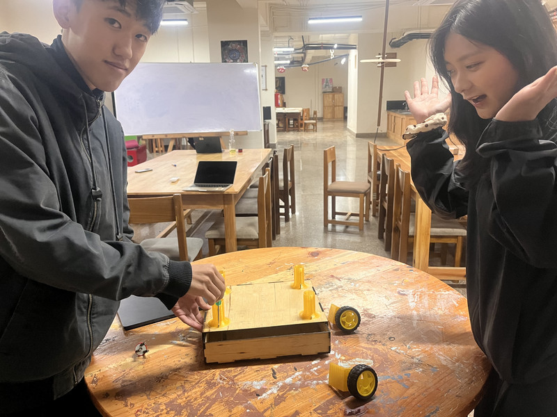
After assembling everything, I realized that there was no way to screw in the motor mounts while still allowing the drawer to slide. I also need to create a few holes on the bottom of the base to allow the motor wires to pass through. Therefore, I need to redesign a few parts of the project. 😌
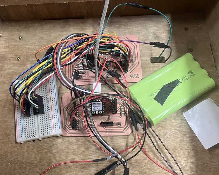
I'm also planning to design and laser cut a small case to contain all the electronics used in the project. (Note: I will be replacing the breadboard with a perf board and will also work on improving the wiring layout to make the connections more organized.😉)
Sir Rico and I talked about the overall design of my project. He suggested making a cart that could carry any backpack instead of building a backpack specifically for the project. I really liked the idea because it would be more flexible, so I started redesigning everything.
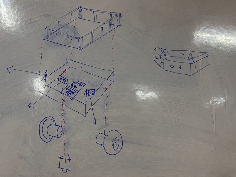
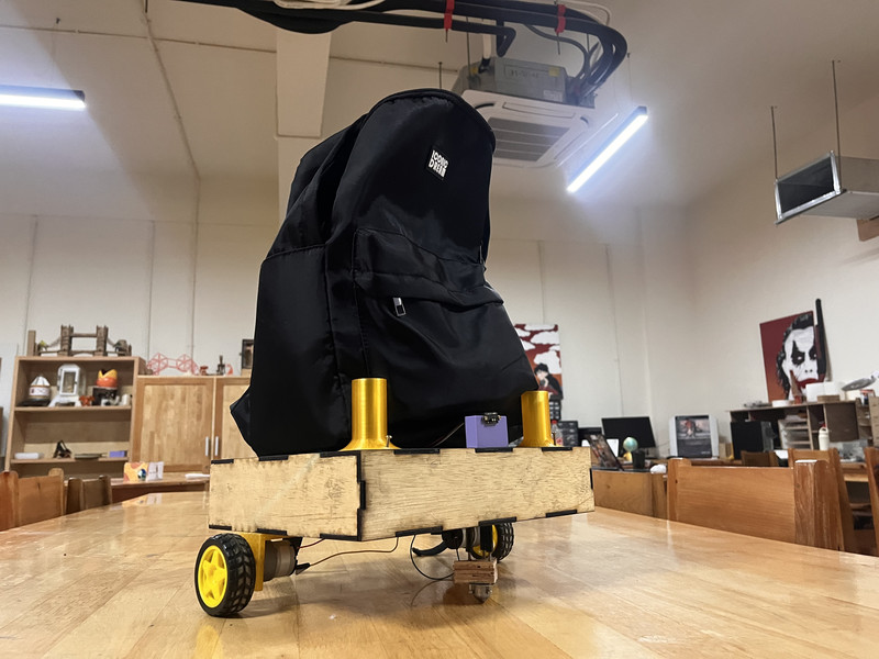
This is the final look of the design now!!! Sir Rico suggested I make a kind of lid so that I can easily acces the electronics and Sir Anith suggested I make a kind of pin-and-hole joint. 😄
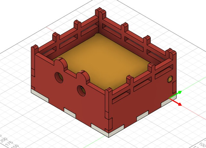
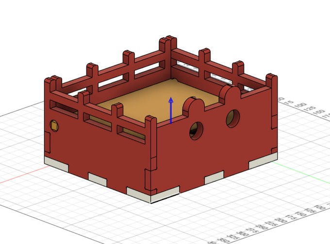
I CNC cut the main body and here is how it looks now!!! 🎉
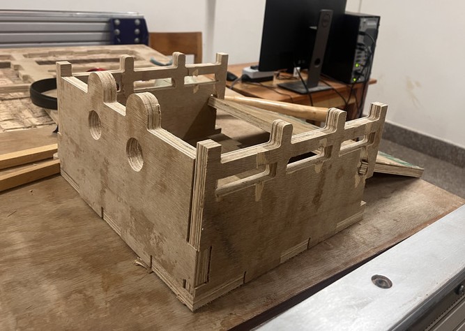
The electronic components will be placed beneath the lid. The wires connected to the sensors will be routed through the 3D-printed mounts, keeping them hidden while leading them directly to the compartment below the lid. ☺️
Further updates and progress will be documented on my Final Project Development page. 😉
This week, I came to the profound realization that if I ever want to graduate from Fab Academy, I'm going to have to start locking in. 🤗