Final Project Development
WEEK 01
Note: The links of the following have been shared on my Project Proposal page.This week, I started by creating a rough design of the backpack on Fusion 360. I had to remake the wheel about 5 times because it wasn't turning out the way I wanted it to. 😅
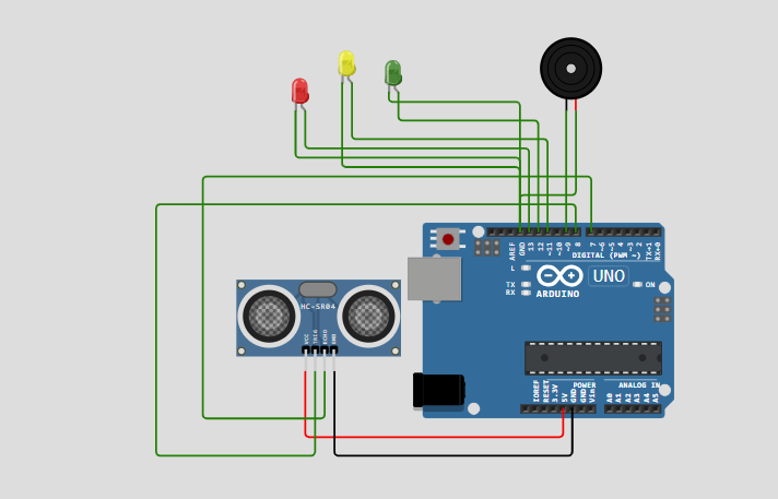
Then I created a rough design (On Canva) of the circuit as well. Since it's the first draft, it might not work. 🤷♀️
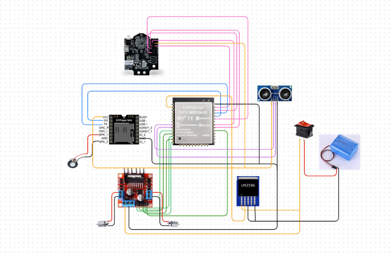
After I did that, I made a simulation using the same logic as the backpack's function.
Here you can see how the backpack decides on whether to move fast or slow, depending on how far away the owner is.
WEEK 02
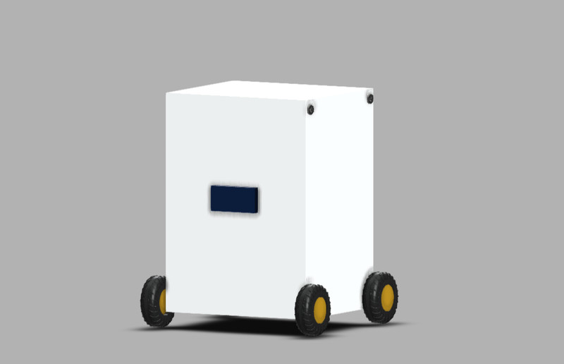
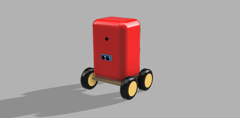
Note: I have shared the full design process for Fusion and Onshape on the Week 2 assignment page.This week, I created a more polished version of the last design that I made on Fusion 360.
I also designed a box in Onshape for my components.
.png)
Cardboard Prototype (04/02/2026)
Today we created a cardboard prototype of our final project. This activity made me realize the fact that there were a lot of important details that I hadn't considered. Also the fact that my artistic skills have a long way to go. ƪ(˘⌣˘)ʃ
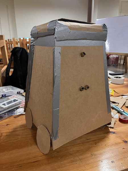
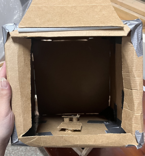
Here are some of the things that I didn’t pay much attention to:
- Find another way to access the circuit. So if something goes wrong after everything is done, I can have a way to check.
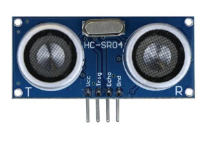
- How to protect ultrasonic sensor and the camera so that when the user puts their books and stuff in, nothing is altered with.
- The wiring part - So that everything is organized and well-hidden.
- What material should the backpack be made of, so that it actually looks like one.
- Battery management system!
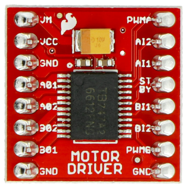
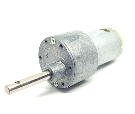
- Should look into using two motors and not four.
- How do I make the backpack light???
Thank you Sir Anith for pointing these out to me! 😄
Moving forward, here is my plan:
-
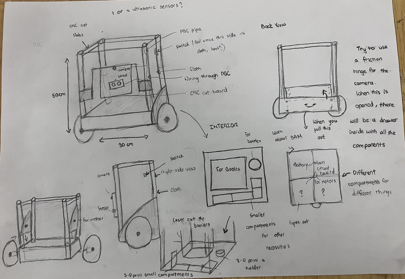
I will first start by creating more detailed sketches of my final project.
- To get a clearer idea of my final project, I am going to start with 3D sketches. The sketches will include both the interior and the exterior.
- As I go, I will also brainstorm some design ideas.
- I will then document the process on this page.
-
I will then do more research on Battery Management System.
- Under this, I will also have to do more research on current, voltage, power and torque as well. 😉
- I will then calculate the runtime of my backpack using this knowledge.
-
Figure out how to tilt the PIxy2 camera at such an angle that it can detect the color marker on the user's back.
- Even though using a QR code was the initial plan, I found out that a Pixy2 camera isn't capable of that which is why I'll have to do more research.
- I might also use 3 ultrasonic sensors instead of just one. 🧐
Note to self:
You have GOT TO go into more detail!
- Work on using multiple ultrasonic sensors simultaneously.
- Make the backpack's center of gravity as low as possible - So that when it turns and stuff, it doesn't topple over.
- How much weight will the backpack be able to carry?
- Heavier weight = Bigger motor = Larger power supply
- Focus on one terrain!!!
- I'm thinking of using a joint to tilt my camera 🤔. I don't know if that is a safe option though.
- I need to make the backpack as light as possible too.
- Widen the base - Should tweak the design a bit.
- Keep all heavy components at the base.
- Maybe attach the wheels a little higher on the frame so that the body hangs lower.
- Design the internal compartments of the backpack in such a way that the contents are closer to the base. For example: Instead of keeping books vertically upright, they could be kept horizontally.
WEEK 03
I worked on a couple of sketches, although there still is a lot that I have to consider.
WEEK 04
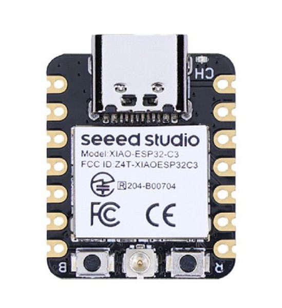
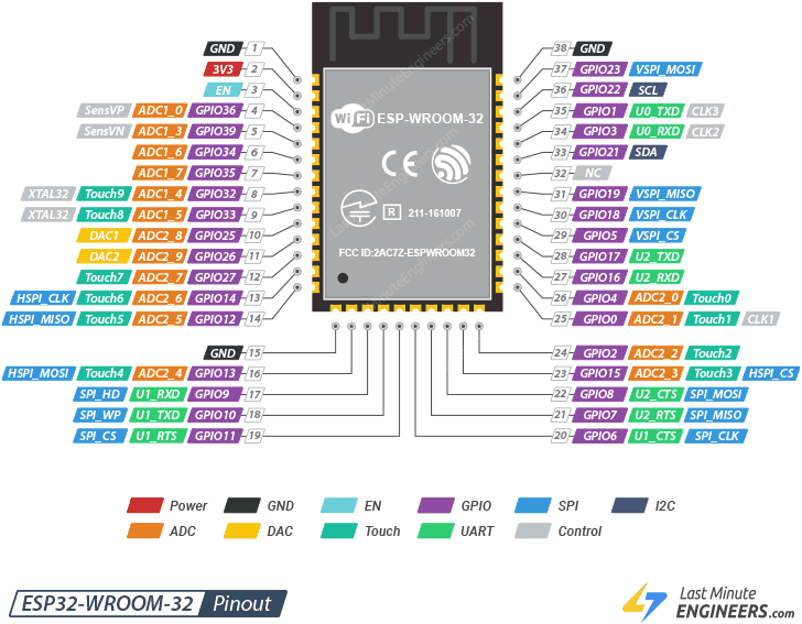
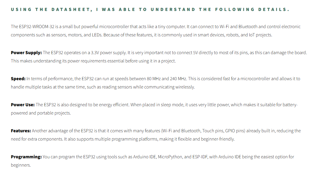
This week, I went through the datasheet for the ESP32-WROOM-32 and found quite a lot of important details.
More can be found on my Week 04 page!
I then created a simulation on Wokwi that can give visual and audio responses based on how far away the object is.
After that I also assembled the cicuit using components that I could find in the lab. 😉
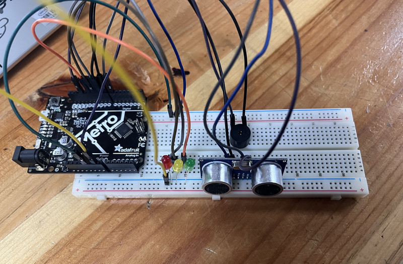
This is how it works (~ ̄▽ ̄)~
WEEK 05
There were still so many things that I hadn't considered. Thank you Sir Rico for pointing them out to me! 😃
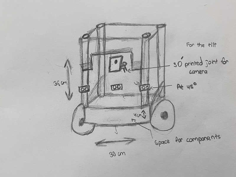
To lower the center of gravity, here are some of the things I plan to do:
WEEK 06: Final Project Board Draft!!!
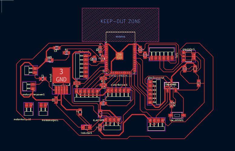
This week, I designed the first draft of my final project board 🤗. Routing the PCB was an absolute nightmare. It took me a really longgggggg time to finish 🙂.
This was my first attempt. There were still many connections that needed to be fixed by adjusting the placement of the components.
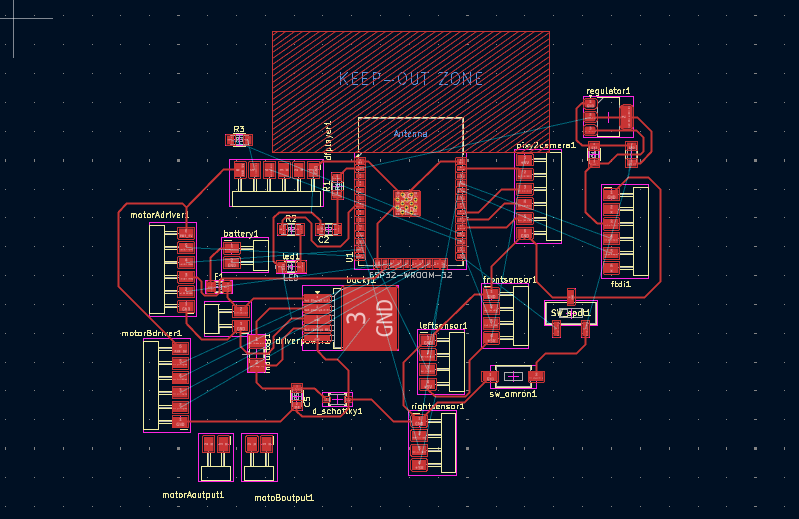
My second attempt was better than the first, but I still needed to adjust the placement of some components to improve the connections.
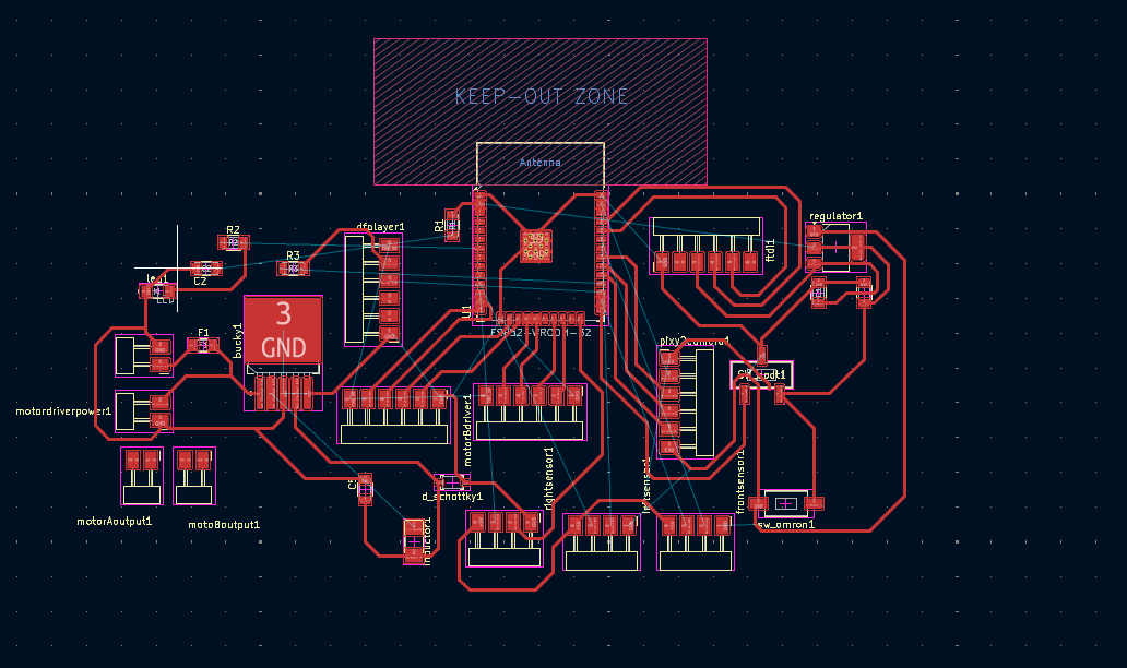
I think the third attempt turned out pretty well, so here is the final look! I had to use 10 0Ω resistors 😅, so I will definitely need to work on improving this in the coming weeks.
Thursday 05/03/2026
Today sir Rico suggested that I use one motor and four wheels. I am not really familiar with this concept so I'll have to explore on that. I don't think the ESP32-WROOM-32 is working out for me so if I have fewer components, I might be able to use another microcontroller 🤔. Sir Rico also suggested that I could connect the TRIG pins of all my ultrasonic sensors to a single pin so that they trigger and send out waves at the same time (I think I should try this out).
WEEK 07
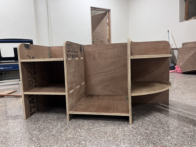
This week, I designed and made a backpack holder! Since it was CNC cutting week, I chose this as my assignment 😁
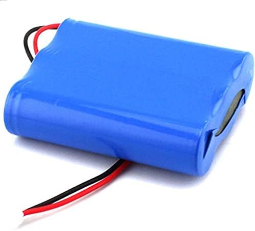
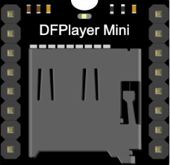
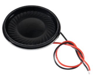
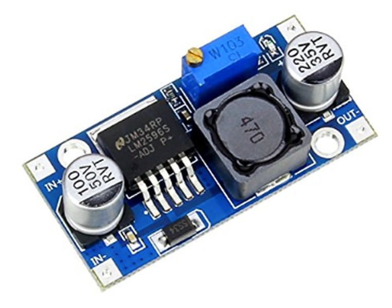
This week, I was also able to get a clearer idea of all of the components that I'll be using. Here is my list for now: