
Week 04: Embedded Programming
Assignments:
Group Assignment
- Explain and compare how different microcontrollers are programmed, including the tools and steps use
- Document your work to the group work page and reflect on your individual page what you learned
Individual Assignment
- Browse through the data sheet for a microcontroller
- Write and test a program for an embedded system using a microcontroller to interact (with input &/or output devices) and communicate (with wired or wireless connections)
Things to Complete This Week
- Browse and document some information from the microcontroller's datasheet
- Programme the simulated board to interact and communicate
- Describe the programming process used
- Include source code
As usual, here is my updated schedule for the week.
.png)
Here is the link to my schedule
Group Assignment
This week, we explored different microcontrollers and their features. We used Arduino IDE to write our code and test out three boards: the Arduino UNO, XIAO ESP32-C3, and the ATtiny44. I personally found this assignment extremely helpful, as it gave me a lot of insight into the capabilities of each board. 😃 Overall, the entire process was both educational as well as exciting!
To access our group assignment, click on this link.
Individual Assignment
ESP32-WROOM-32
I went through the datasheet for the ESP32-WROOM-32 to better understand its features, as I am planning to use this module for my final project. Here is the link to the datasheet.
Here are the main parts of an ESP32-WROOM-32 and its functional diagram:
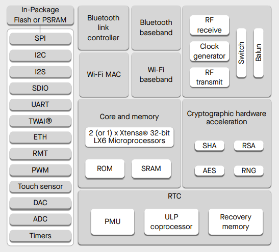
Using the datasheet, I was able to understand the following details.
The ESP32-WROOM-32 is a small but powerful microcontroller that acts like a tiny computer. It can connect to Wi-Fi and Bluetooth and control electronic components such as sensors, motors, and LEDs. Because of these features, it is commonly used in smart devices, robots, and IoT projects.
Power Supply: The ESP32 operates on a 3.3V power supply. It is very important not to connect 5V directly to most of its pins, as this can damage the board. This makes understanding its power requirements essential before using it in a project.
Speed: In terms of performance, the ESP32 can run at speeds between 80 MHz and 240 MHz. This is considered fast for a microcontroller and allows it to handle multiple tasks at the same time, such as reading sensors while communicating wirelessly.
Power Use: The ESP32 is also designed to be energy efficient. When placed in sleep mode, it uses very little power, which makes it suitable for battery-powered and portable projects.
Features: Another advantage of the ESP32 is that it comes with many features (Wi-Fi and Bluetooth, Touch pins, GPIO pins) already built in, reducing the need for extra components. It also supports multiple programming platforms, making it flexible and beginner-friendly.
Programming: You can program the ESP32 using tools such as Arduino IDE, MicroPython, and ESP-IDF, with Arduino IDE being the easiest option for beginners.
Pin Layout
The ESP32 has many pins, and each one has a specific purpose. Some pins are used only for input, while others are involved in the boot process. Using the wrong pin can cause the board to not work properly. 😉
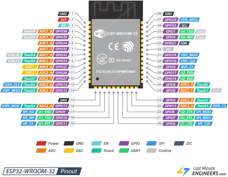
Here are some important pins to remember:
- VCC: Supplies 3.3V power to the ESP32.
- GND: Acts as the ground for the circuit.
- GPIO: Connects sensors, LEDs, or buttons and can read or send signals.
- EN: Turns the ESP32 on or off (reset if LOW).
- BOOT / GPIO0: Puts the ESP32 into programming mode when held LOW.
- TX / RX: Handles serial communication and code uploading.
- ADC: Reads analog values from sensors like light or temperature.
Wokwi
I started by creating an LED simulation in Wokwi, which is really easy to use. You can try it yourself by clicking on this link. Here are the steps that I followed:
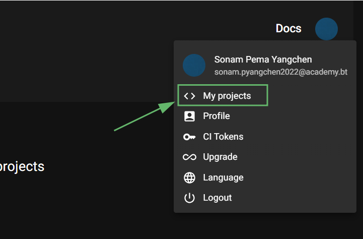
1. Before getting started, make sure that you are signed in. Then click on your profile and go to "My projects"
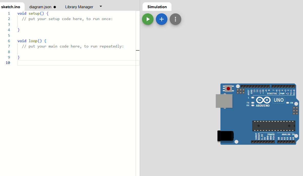
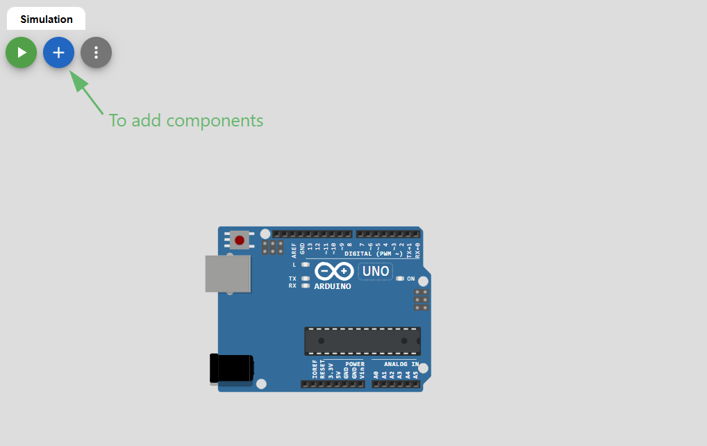
2. After that, click on "New project" and select "Arduino UNO". Your workspace should now look like this:
3. Click on the plus button and add an LED, a resistor and a button.
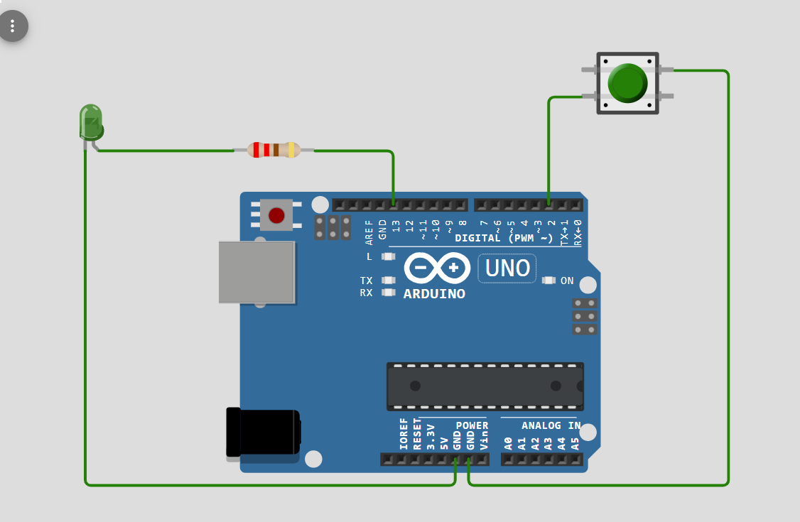
4. Connect the long leg of the LED (Anode) to pin 13 through a 220Ω resistor, and the short leg (Cathode) to GND. Connect one side of the button to pin 2 and the other side to GND. It should now look like this:
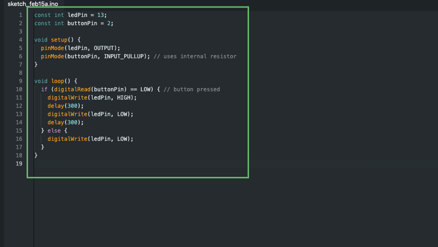
As for the code, I used ChatGPT to create one using the prompt: "Can you write an Arduino program that makes an LED light up when a button is pressed?"
                        const int ledPin = 13;
                        const int buttonPin = 2;

                        void setup() {
                        pinMode(ledPin, OUTPUT);
                        pinMode(buttonPin, INPUT_PULLUP); // uses internal resistor
                        }

                        void loop() {
                        if (digitalRead(buttonPin) == LOW) { // button pressed
                            digitalWrite(ledPin, HIGH);
                            delay(300);
                            digitalWrite(ledPin, LOW);
                            delay(300);
                        } else {
                            digitalWrite(ledPin, LOW);
                        }
                        }
I then made Chat GPT explain each function in simple terms. This is what I understood:
- const int ledPin = 13; –> This creates a constant variable named ledPin and sets it to 13.
- const int buttonPin = 2; –> Creates a constant variable named buttonPin and sets it to 2.
- void setup() { … } –> Runs once to prepare pins and settings.
- pinMode(ledPin, OUTPUT); –>Makes the LED pin an output.
- pinMode(buttonPin, INPUT_PULLUP); –> Makes the button pin an input with an internal pull-up.
- void loop() { … } –> Repeats continuously to check the button and control the LED.
- if (digitalRead(buttonPin) == LOW) { … } –> Checks if the button is pressed.
- digitalWrite(ledPin, HIGH); –> Turns the LED on.
- delay(300); –> Waits for 0.3 seconds.
- digitalWrite(ledPin, LOW); –> Turns the LED off.
- else { digitalWrite(ledPin, LOW); } –> Keeps the LED off if the button isn’t pressed.
Here is my circuit! 😄
Assembling
I decided to try out my circuit in real life and for programming the board, I made use of Arduino Ide. Arduino Ide is an open-source application that is used for writing, compiling and uploading code. You can download it by clicking on this link.
Here are the steps that I followed:
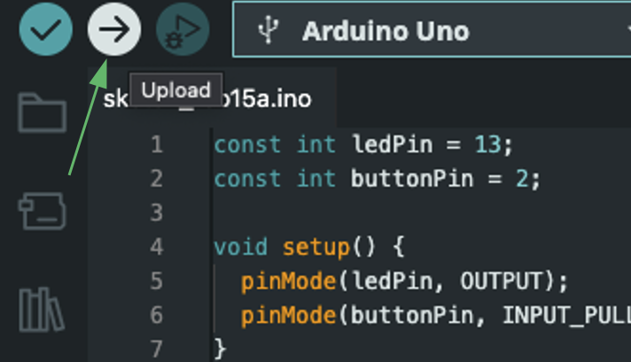
1. Open Arduino Ide and paste your code.
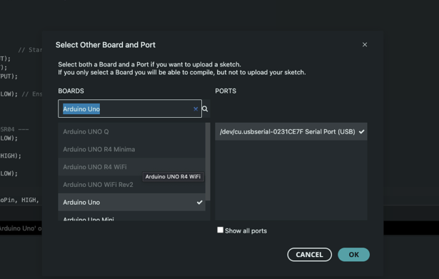
2. Connect the USB to your computer and select your port then board.
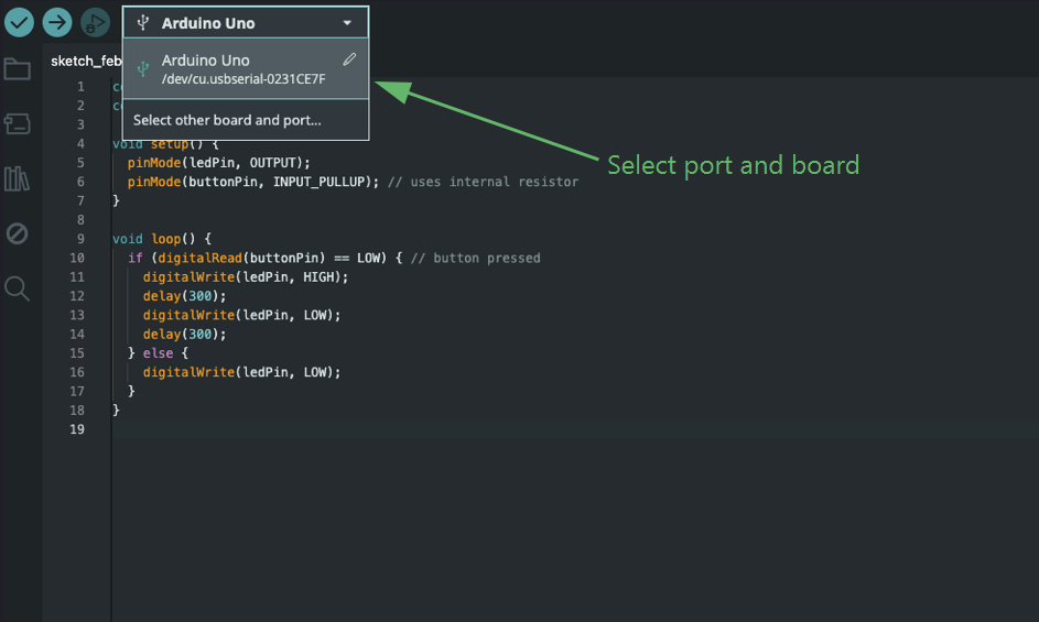
3. Click this to upload the code! 😃
Here you can see how the LED blinks whenever the button is pressed 😁
Here is the link to the simulation
After that, I decided to create another simulation that followed the same logic as my final project. To do this, I used Wokwi again and repeated the same steps I had used for the first simulation.
Here is the link to the simulation
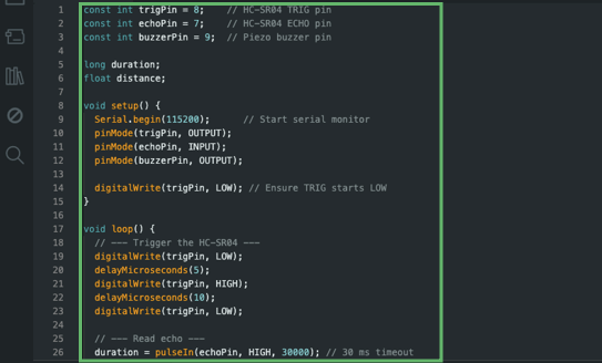
I used ChatGPT to create a code and this was the prompt that I gave: Can you give me a code that will make three different LEDs light up and a buzzer beep depending on the distance that an ultrasonic sensor detects? Red for when the object is too far or not detectable, yellow for when it is too close and green for when it's in the perfect range.
const int trigPin = 8;
const int echoPin = 7;
const int buzzerPin = 9;

const int greenLED = 12;
const int yellowLED = 11;
const int redLED = 10;

long duration;
float distance;

void setup() {
  Serial.begin(115200);

  pinMode(trigPin, OUTPUT);
  pinMode(echoPin, INPUT);
  pinMode(buzzerPin, OUTPUT);

  pinMode(greenLED, OUTPUT);
  pinMode(yellowLED, OUTPUT);
  pinMode(redLED, OUTPUT);

  digitalWrite(trigPin, LOW);
}

void loop() {
  // Measure distance
  digitalWrite(trigPin, LOW);
  delayMicroseconds(5);
  digitalWrite(trigPin, HIGH);
  delayMicroseconds(10);
  digitalWrite(trigPin, LOW);

  duration = pulseIn(echoPin, HIGH, 30000);

  if (duration == 0) {
    distance = -1;
    Serial.println("No echo detected");
  } else {
    distance = duration * 0.034 / 2;
    Serial.print("Distance: ");
    Serial.print(distance);
    Serial.println(" cm");
  }

  // Reset LEDs
  digitalWrite(greenLED, LOW);
  digitalWrite(yellowLED, LOW);
  digitalWrite(redLED, LOW);

  // LED + buzzer logic
  if (distance == -1) {
    digitalWrite(redLED, HIGH);
    tone(buzzerPin, 1500);
    Serial.println("Warning: No object detected!");
  }
  else if (distance < 10) {
    digitalWrite(yellowLED, HIGH);
    tone(buzzerPin, 400);
    Serial.println("Alert: Object very close!");
  }
  else if (distance > 50) {
    digitalWrite(redLED, HIGH);
    tone(buzzerPin, 1000);
    Serial.println("Warning: Object too far!");
  }
  else {
    digitalWrite(greenLED, HIGH);
    noTone(buzzerPin);
    Serial.println("Object within safe range.");
  }

  delay(500);
}
I then made Chat GPT explain each function in simple terms. Here is what I understood:
- void setup() { … } –> This runs once at the start to prepare the serial monitor, sensor pins, LEDs, and buzzer.
- void loop() { … } –> This runs over and over, constantly checking the distance and updating the feedback.
- Serial.begin(115200); –> Starts communication with the computer to print distance values and warnings.
- pinMode(trigPin, OUTPUT); –> Sets the trigger pin to send out ultrasonic pulses.
- pinMode(echoPin, INPUT); –> Sets the echo pin to receive the reflected pulse.
- pinMode(buzzerPin, OUTPUT); –> Allows the buzzer to produce sound.
- pinMode(greenLED, OUTPUT); –> Configures the LED pins so they can be turned on and off.
- digitalWrite(trigPin, HIGH); –> Sends a short ultrasonic pulse to measure distance.
- pulseIn(echoPin, HIGH, 30000); –> Measures how long the pulse takes to return, stopping after a timeout.
- if (duration == 0) { … } –> This checks if the sensor failed to detect any objects.
- distance = duration * 0.034 / 2; –> Converts the pulse travel time into a distance in centimeters.
- digitalWrite(greenLED, LOW); –> Resets the LEDs by turning them off before choosing the new color.
- tone(buzzerPin, frequency); –> Makes the buzzer beep at different pitches for different distance warnings.
- noTone(buzzerPin); –> Turns the buzzer off when the distance is safe.
- delay(500); –> Pauses the system for half a second before taking the next measurement.
Here you can see that based on the distance, the system provides different visual and audio feedback.😄
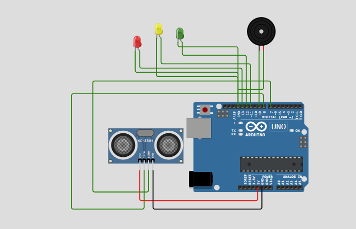
After creating the simulation, I tried to assemble the circuit in real life ^_^. I started by copying and pasting the code from Wokwi onto Arduino Ide. Then I selected the port and board.
Here is how the setup looks like (This was before I uploaded the code):
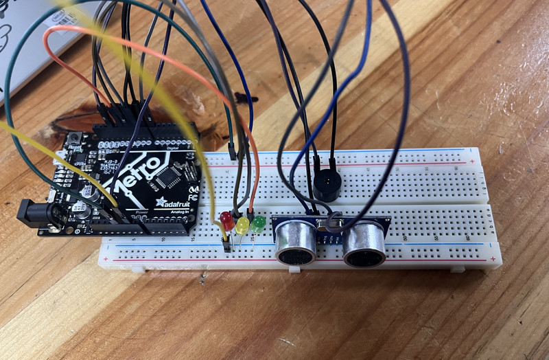
Here is the outcome!!!
At the start of the week, I was a bit worried since I had very little programming experience and wasn’t sure if I would be able to complete my assignments. However, everything worked out and I was able to finish on time! Along the way, I was able to learn a lot of cool stuff as well 😄.
That is all for this week.