Mechanical and Machine Design
Here is the group assignment for this week:
-
Design a machine that includes mechanism + actuation+ automation + function + user interface
-
Build the mechanical parts and operate it manually
-
Document the group project and your individual contribution
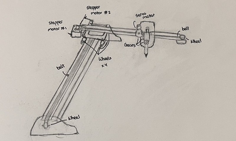
For this week’s group assignment, we agreed on creating a CNC pen plotter (after a lot of braintstorming 😄). A CNC pen plotter is like an automated drawing machine that can accurately write or draw things on a plain surface.
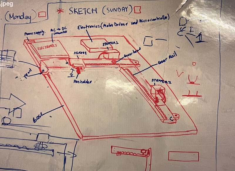
We made some modifications to the initial design because it had a few gaps and wasn’t very practical. 🤓
| | |
|--------|--------|
|  |
|  |
|
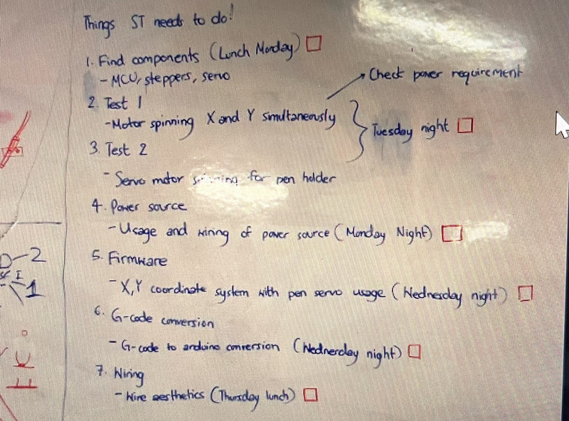
After we had the design planned out, we divided the work between the three of us:
| | |
|--------|--------|
|  |
|  |
|
Note: More detailed steps for each aspect can be found in our individual documentation 😉.
1. Designing and Fabrication
These were all the parts that we designed and printed out:
- The frames
 |
 |
 |
 |
- The top and bottom intersection parts
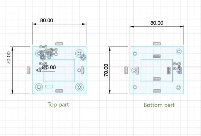 |
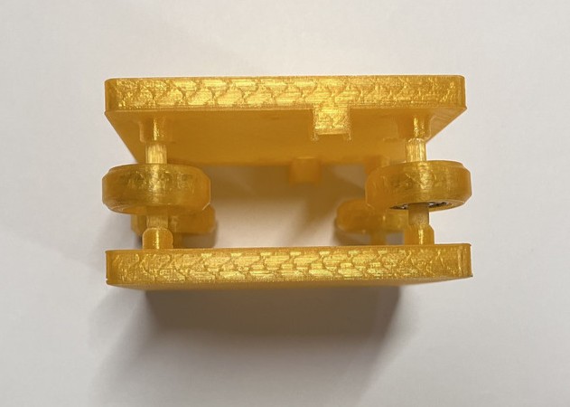 |
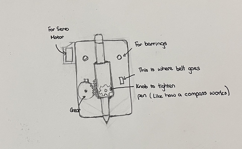
- The penholder parts
 |
 |
 |
 |
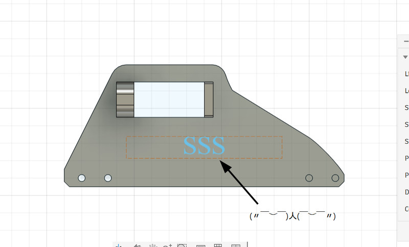
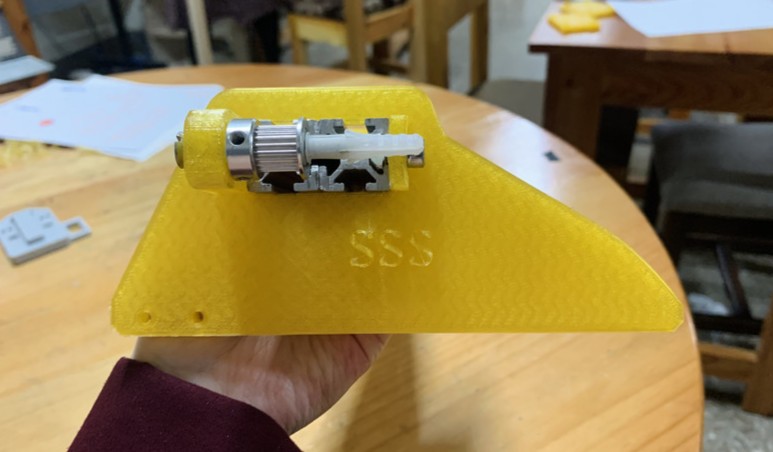
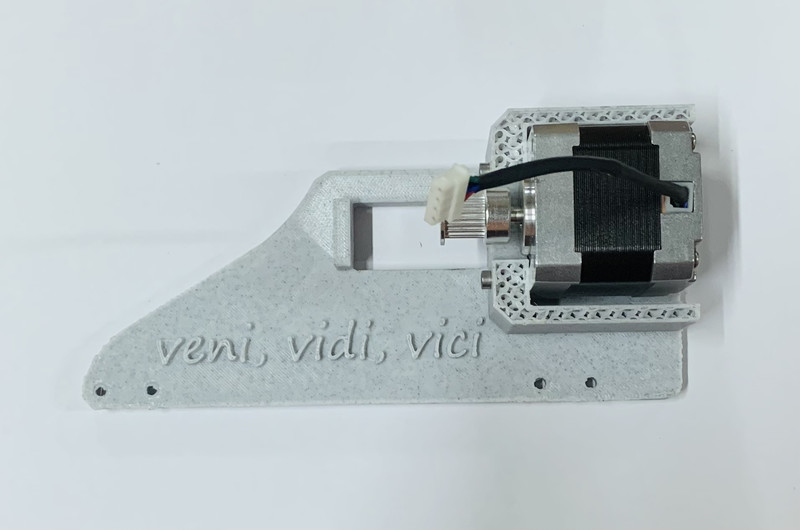
- Holder for stepper motor shaft
 |
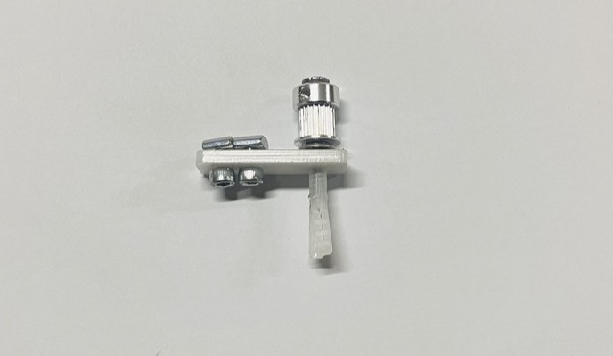 |
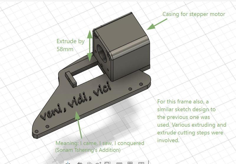
- Holder for stepper motor
 |
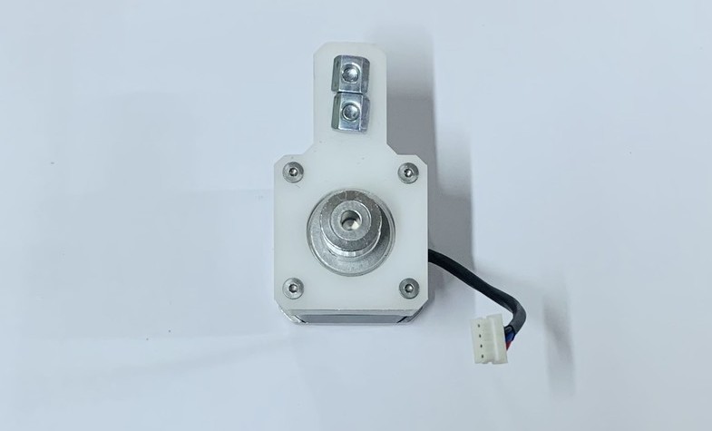 |
Electronics
Here is a list of all the components that we used:
| Component | Spec | Quantity |
|---|---|---|
| Arduino Nano | ATmega328P | 1 |
| Stepper Motor | NEMA 17 — Jameco 42BYG44B, 1A, 4V rated | 2 |
| Motor Driver | A4988 module (clone, Rs = 0.1Ω) | 2 |
| Servo | MG90S | 1 |
| Capacitor | 100µF electrolytic | 1 |
| Power Supply (motors) | 12V 5A | 1 |
| Power Supply (logic) | 5V 2.5A | 1 |
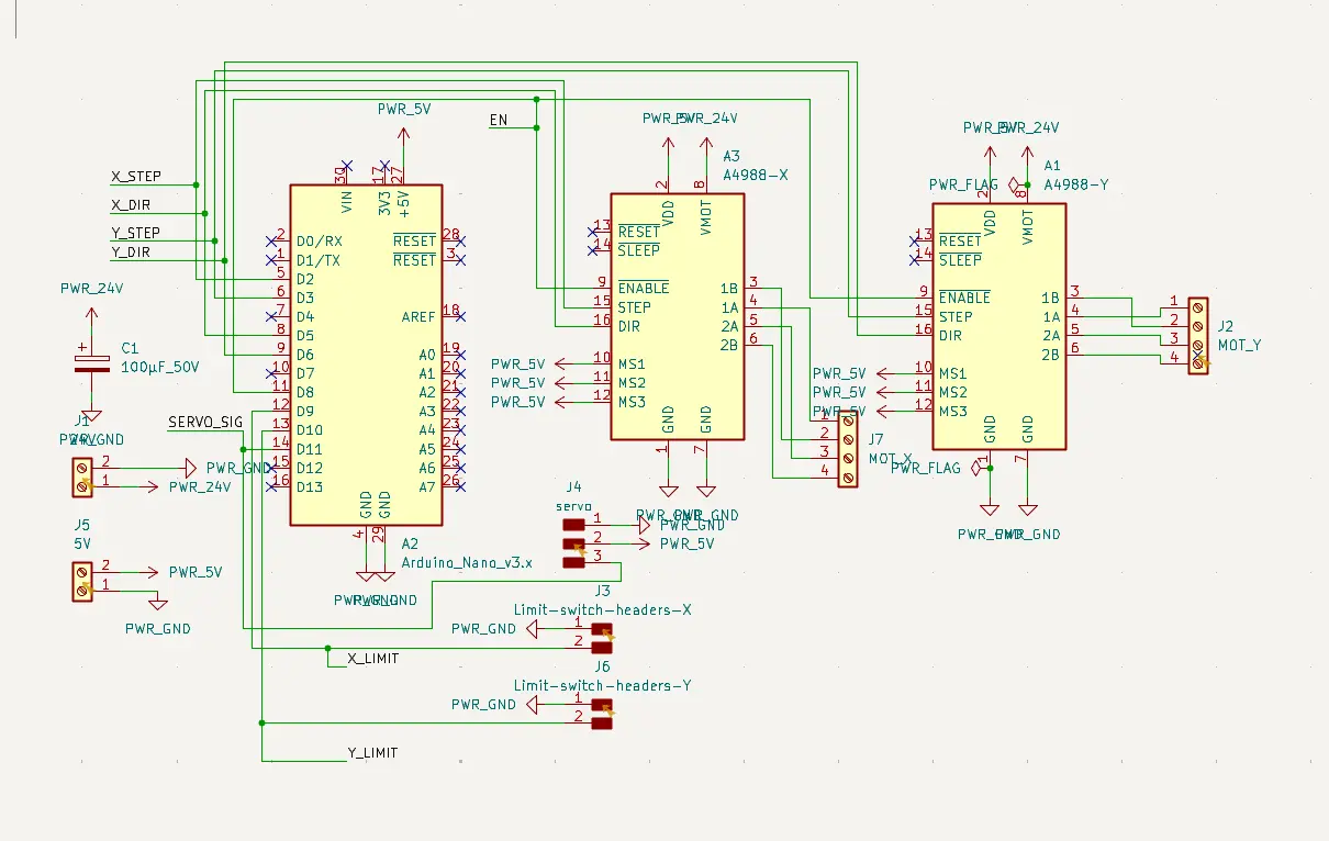
Making custom PCB
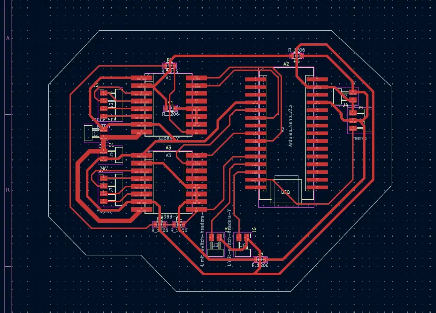
A custom PCB was designed in KiCad.
The wiring was done according to the standard GRBL pin mapping:
| Signal | Arduino Nano Pin |
|---|---|
| X STEP | D2 |
| X DIR | D5 |
| Y STEP | D3 |
| Y DIR | D6 |
| EN (Enable) | D8 |
| Servo PWM | D11 |
After designing the schematic, the PCB was laid out in KiCad by routing all connections manually and making power traces thicker to safely handle motor current. The board outline was added using edge cuts, and the design was checked in 3D before fabrication
 |
 |
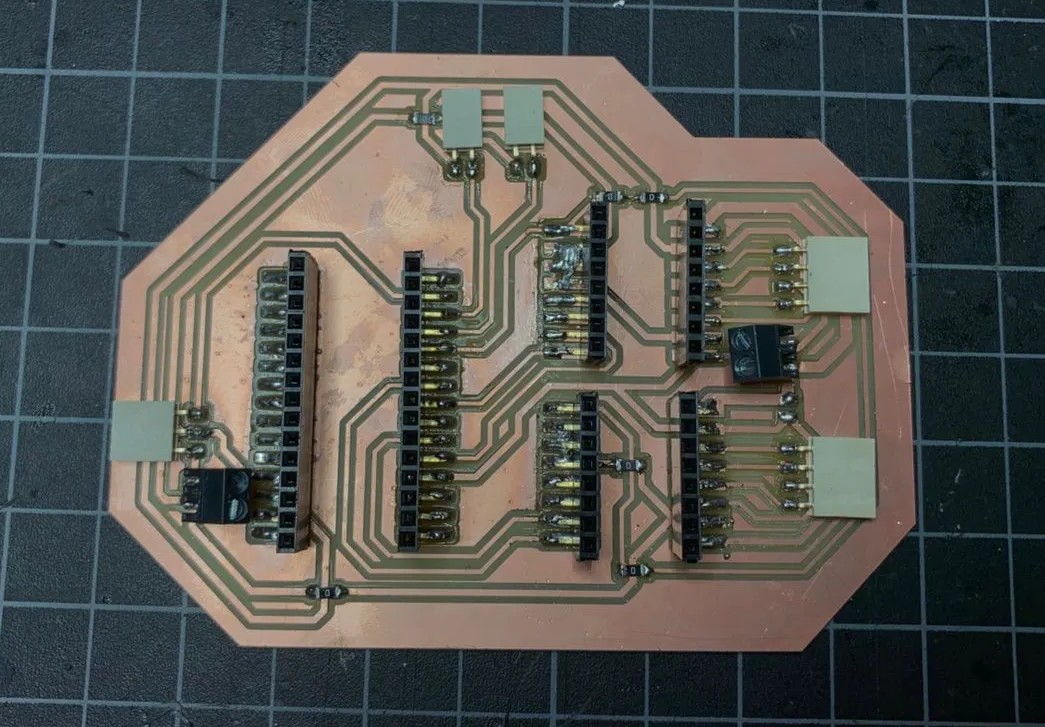
Once the design for the custom PCB was complete, required RML files were generated using Mods CE and the Roland SRM-20 milling machine was used to fabricate the PCB. After milling, all the components were soldered and connections were carefully checked to ensure that there were no short circuits.
Here is how it came out!!! 🤗😄
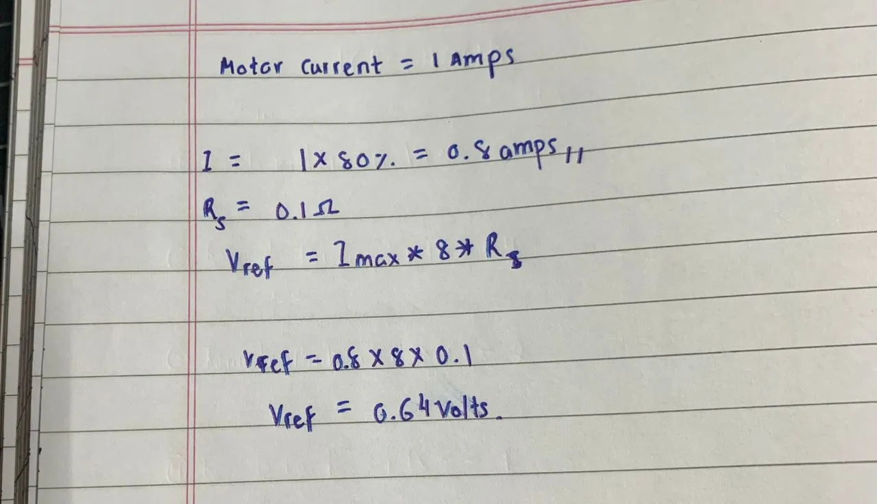
Before powering the motors, the A4988 drivers were calibrated by setting the current limit (Vref). Based on calculations, the target value was 0.64V, and both drivers were adjusted using a multimeter until they matched this value.
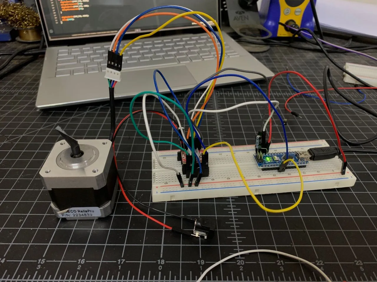
Initial testing was performed on a breadboard to verify motor functionality and determine suitable speed settings. Once confirmed, the setup was transferred to the custom PCB, where both motors were tested individually and together to ensure proper operation.
 |
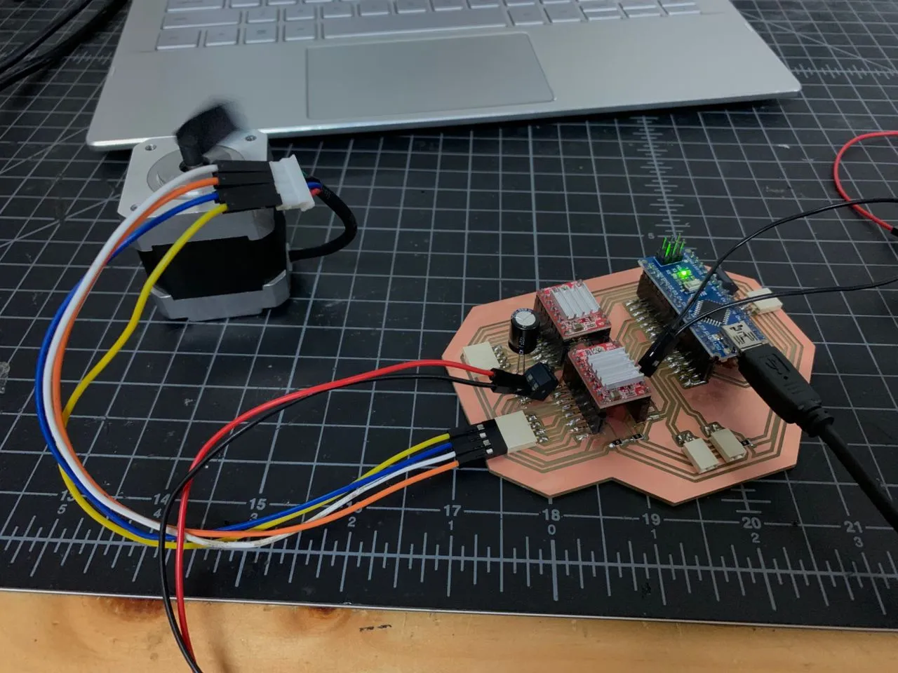 |
The full PCB was then tested with both motors. Once the enable pin was correctly set to LOW in code, both motors worked properly. They were tested individually, together, in opposite directions, and independently, and all cases worked correctly
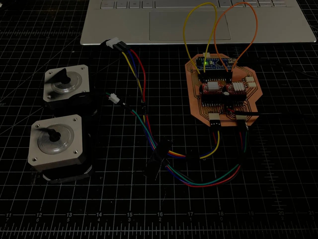
Same Direction
Opposite Direction
The servo motor (responsible for lifting and lowering the pen) was then tested and calibrated to determine accurate angles for pen-up and pen-down positions. 90° worked as pen-up and 0° as pen-down when mounted on the holder.
GRBL firmware was then installed using the grbl-servo version, which allows servo control using M3/M5 commands.
Here are the steps that were followed:
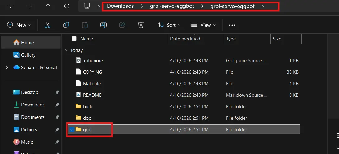
I downloaded the grbl-servo ZIP from the cprezzi/grbl-servo GitHub repository.
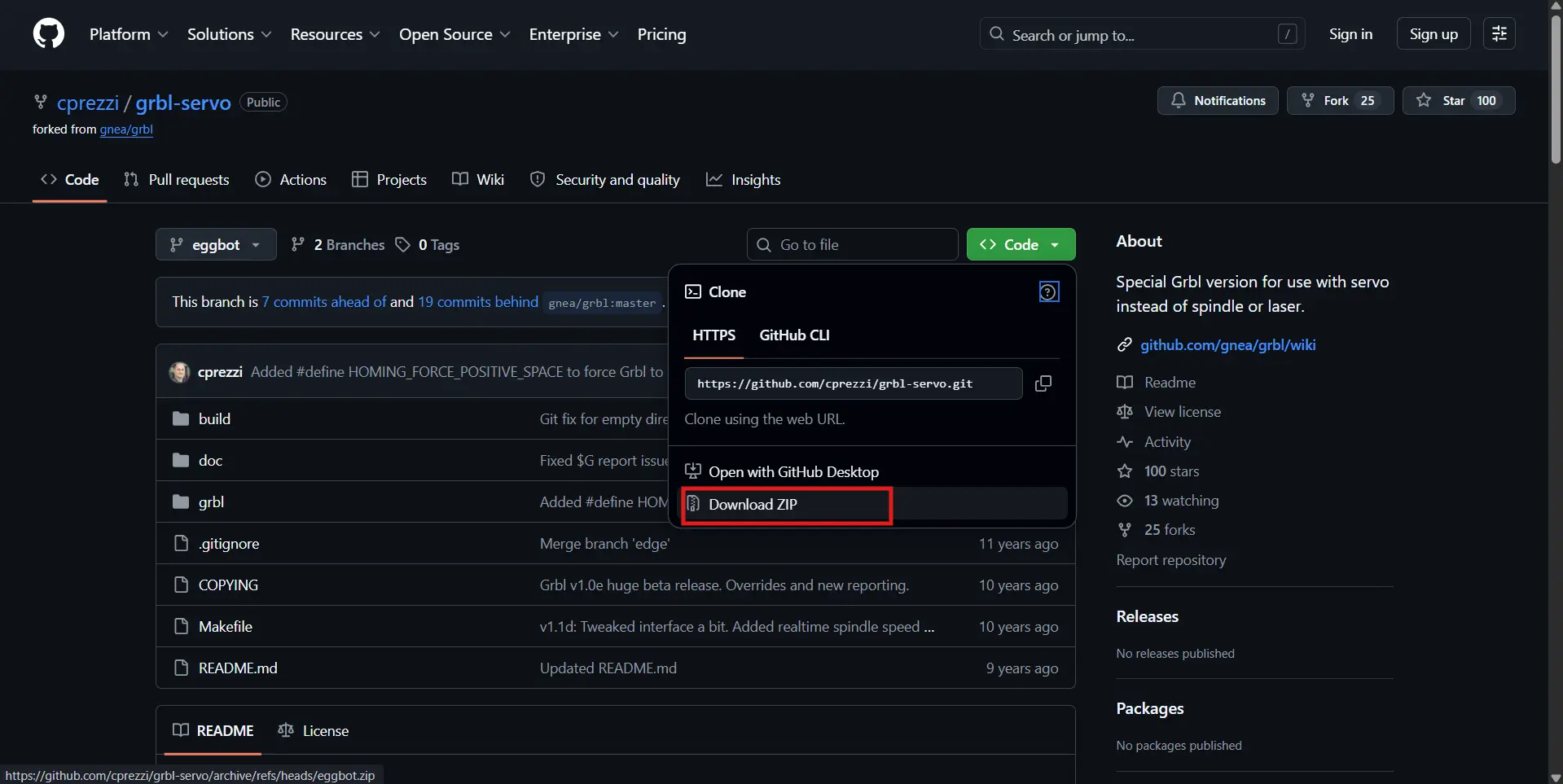
Extracted the ZIP and found the inner grbl folder.
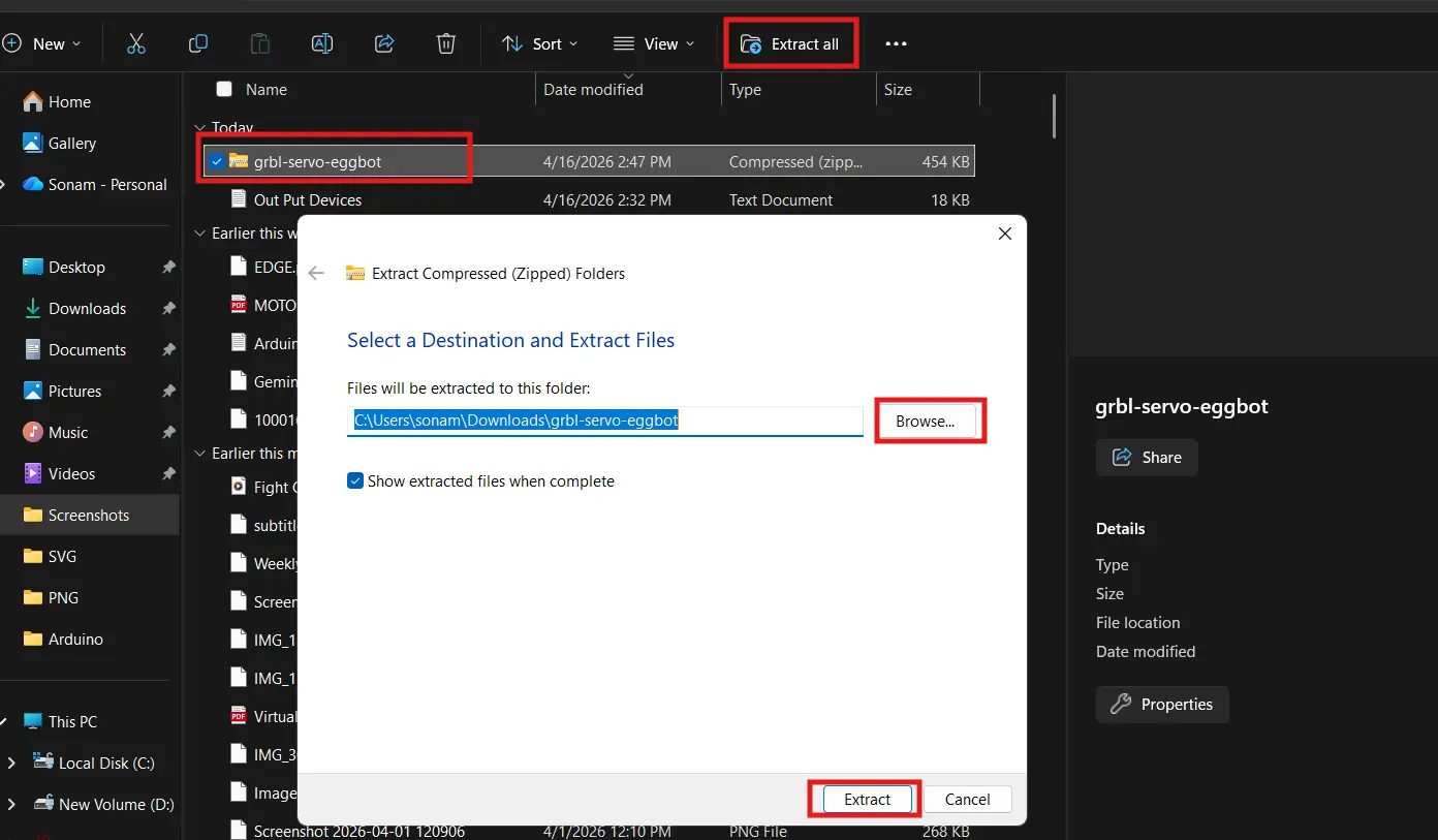
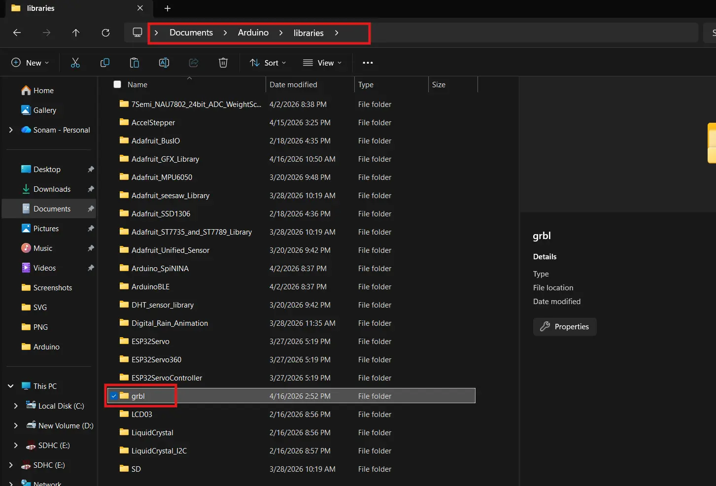
Then copied just that inner grbl folder into Documents → Arduino → libraries.
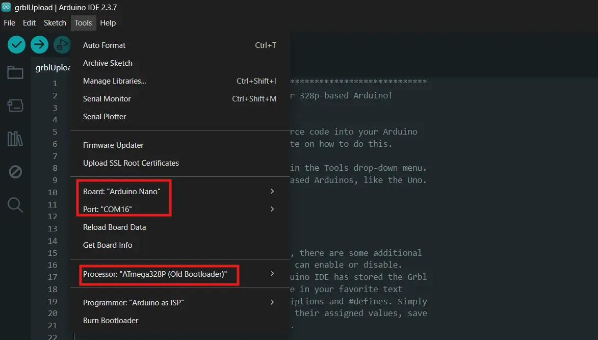
Uploading
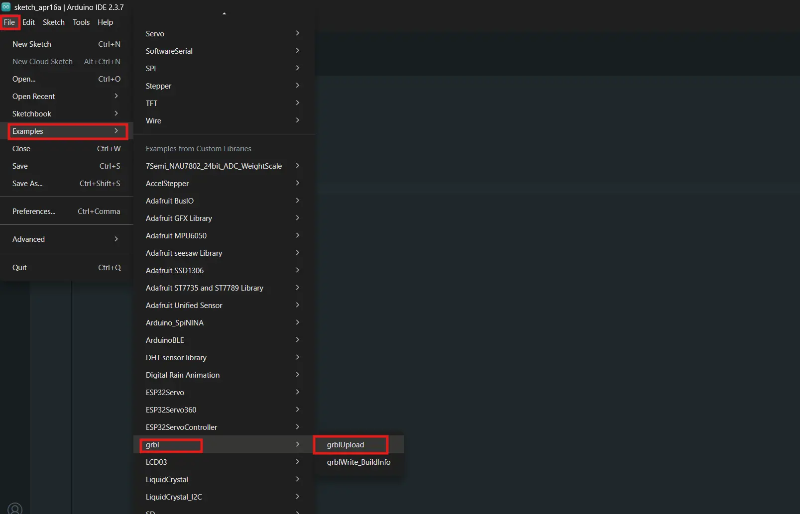
I opened File → Examples → grbl → grblUpload and uploaded it to the Nano.
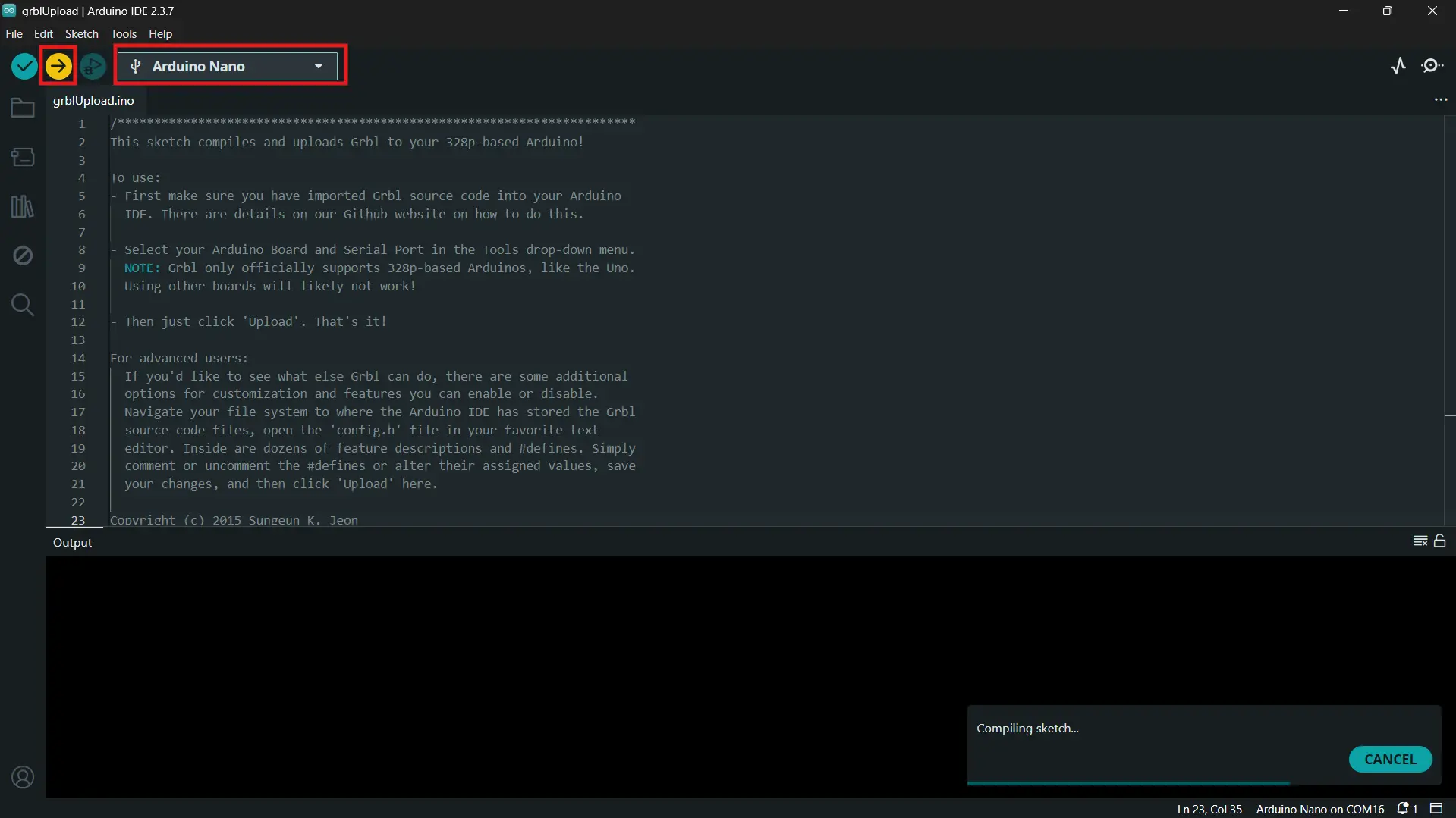
At first, the board did not respond due to a driver and bootloader issue. This was fixed by installing an older CH340 driver and selecting the “Old Bootloader” option. After that, GRBL worked correctly. 🥳
| Setting | Value |
|---|---|
| Board | Arduino Nano |
| Processor | ATmega328P (Old Bootloader) |
| CH340 driver | Version 3.7.2022.01 |
| Port | COM17 |
| Baud (upload) | 57600 |
To test movement, Universal G-code Sender (UGS) was used. Both X and Y axes responded correctly to movement commands and manual control
The x and the y axis rods move! 🥳
Control software was then used to run the system. Universal G-code Sender (UGS) allowed manual motor control, while GRBL-Plotter was used to send drawing commands. The system successfully followed G-code, with both motors and the servo working together properly.
At this point, the entire system (from PCB to firmware to motion control) was fully working 😄.
Designing the Case
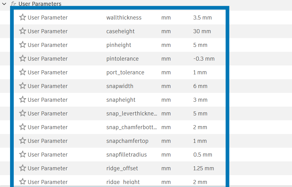
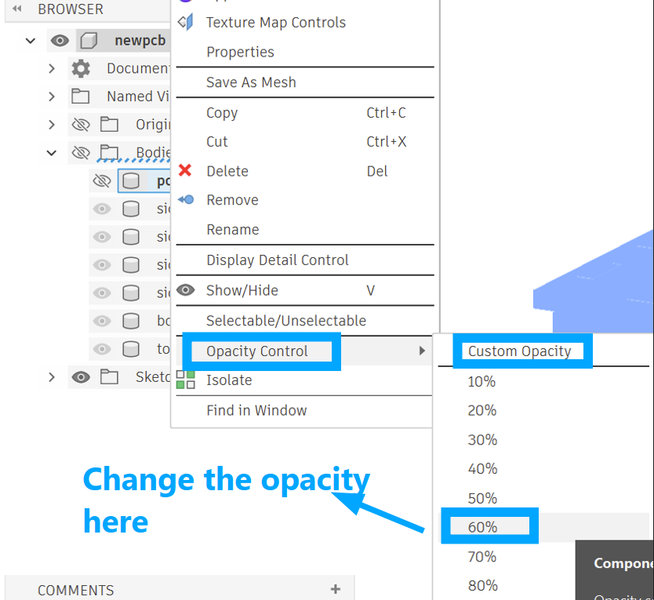
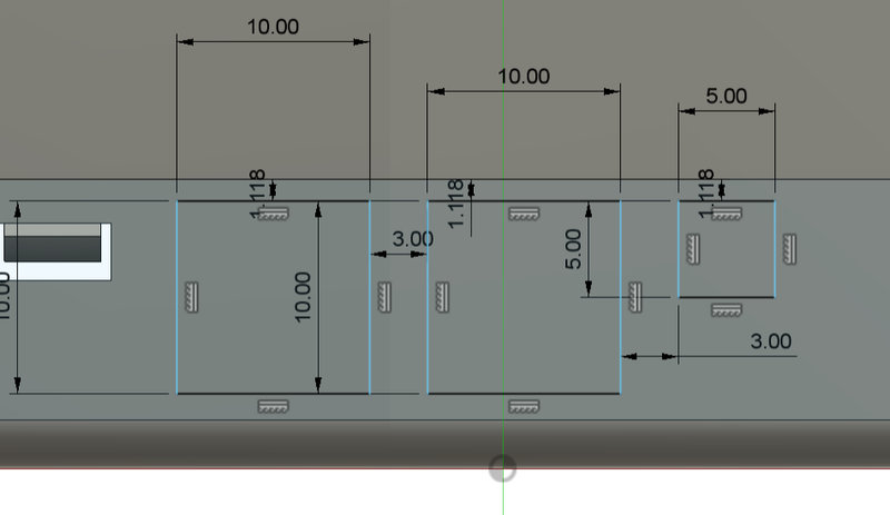
Fusion 360 was used for all designs. For the casing (of the pcb), an Arduino Nano was used as the reference model. Length, width, and height were set as adjustable parameters for flexibility. The model’s opacity was reduced to 60% to clearly view internal components.
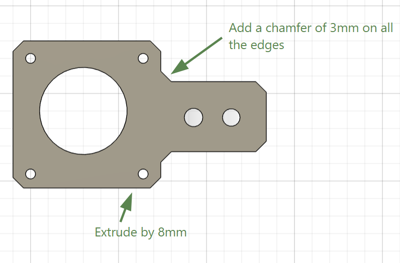
Dimensions were extended and then the shell toolwas used to hollow out the box by a thickness of 3.5mm
 |
 |
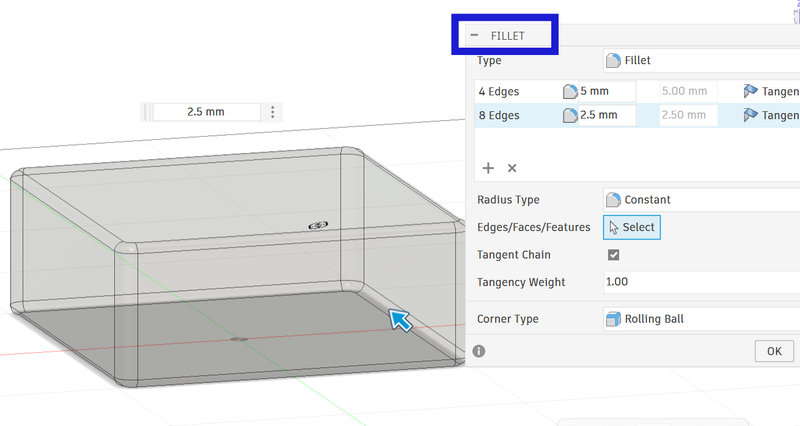
After using the fillet tool to round certain edges, holes were also created for the wiring
 |
 |
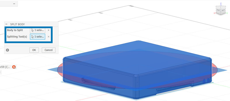
The body was then split, with the top being the lid and the bottom being the bottom.
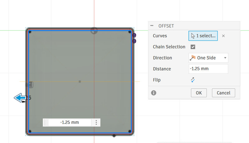
The Offset tool was used to form the ridge for the container.
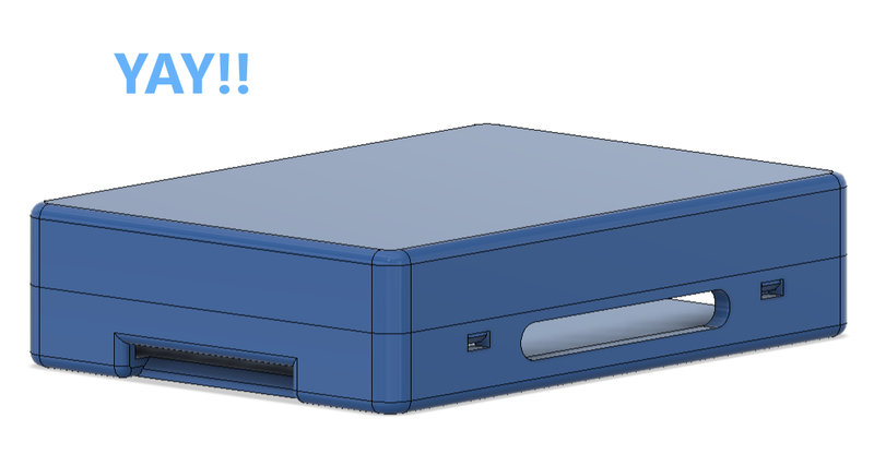
Screw holes (2.5 mm) were added to fix the casing to a wooden base. A chamfered hinge was designed for the lid and mirrored using a midplane to create additional hinges. Here is the final look! 🥳
Our initial plan was to 3D print the casing but since our printer was giving us a lot of problems, we decided to laser cut it instead. 🥸
For that, some modifications weere made to the design.
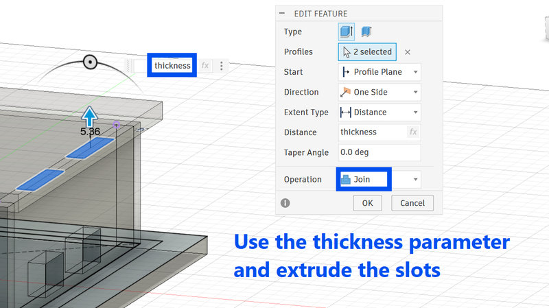
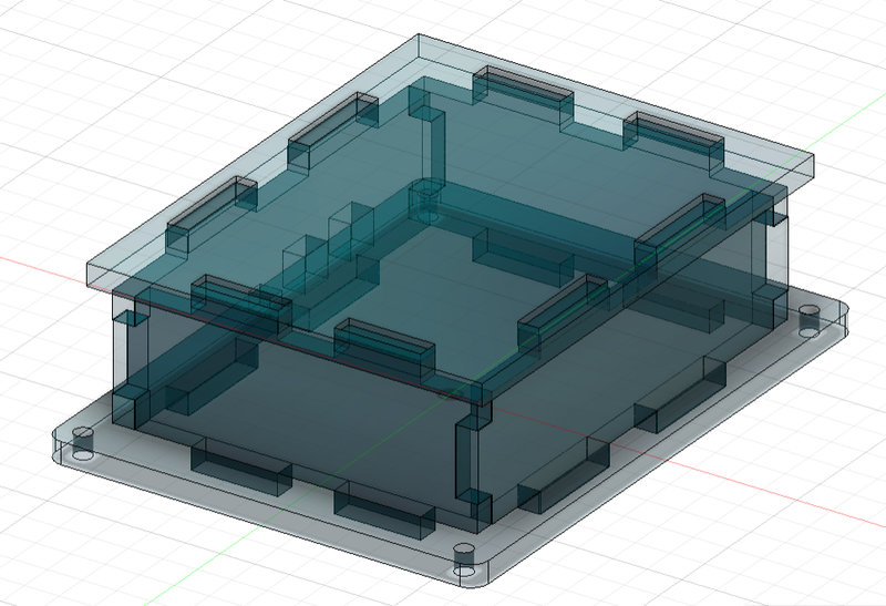
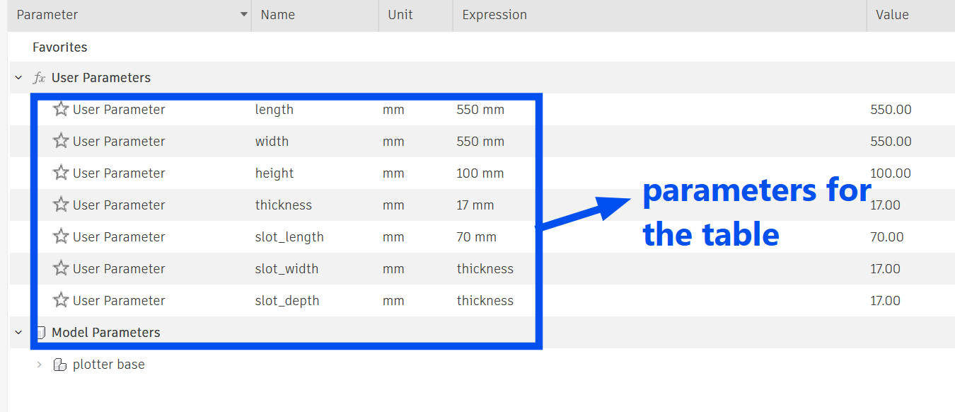
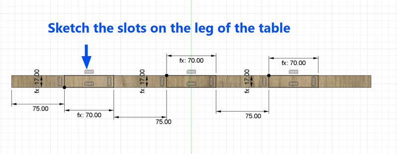
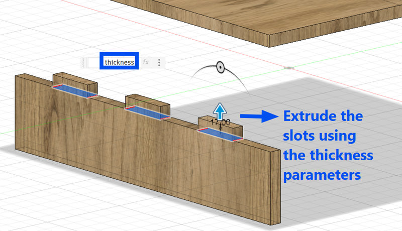
Using the earlier parameters, a sketch of the pcb base was made and then each wall was extruded as a new body.
The thickness parameter was used to extrude each of the slots.
Here is how it turned out!!! 😄🤗
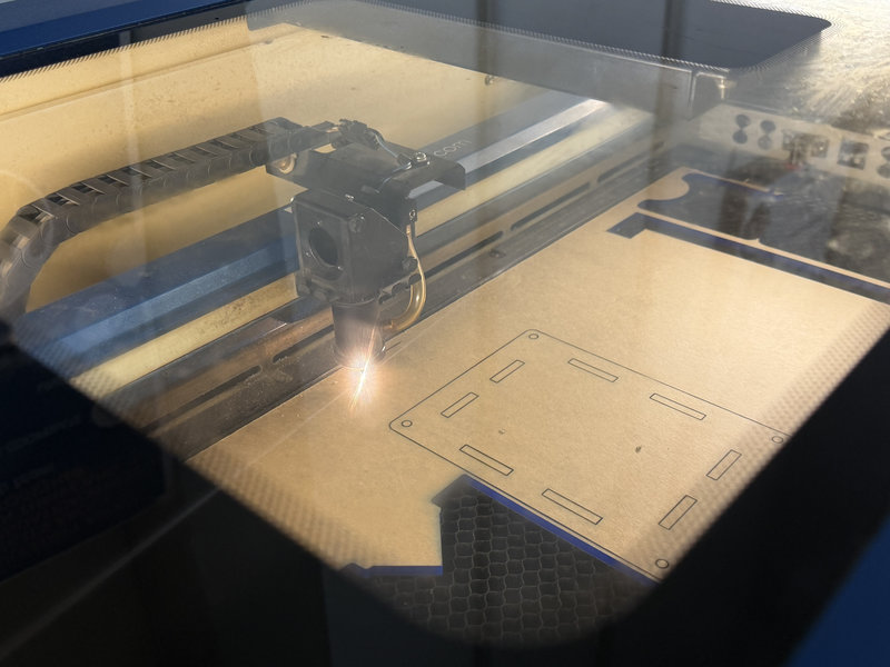
Lasercutting
 |
 |
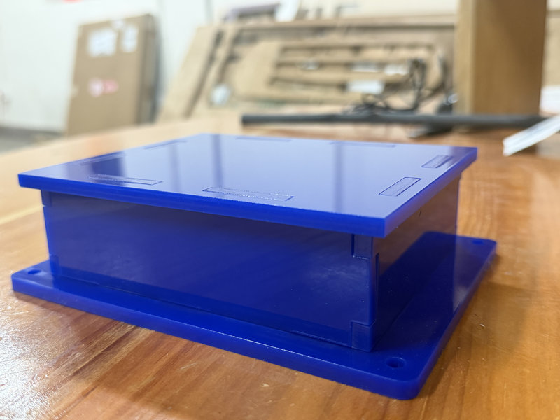
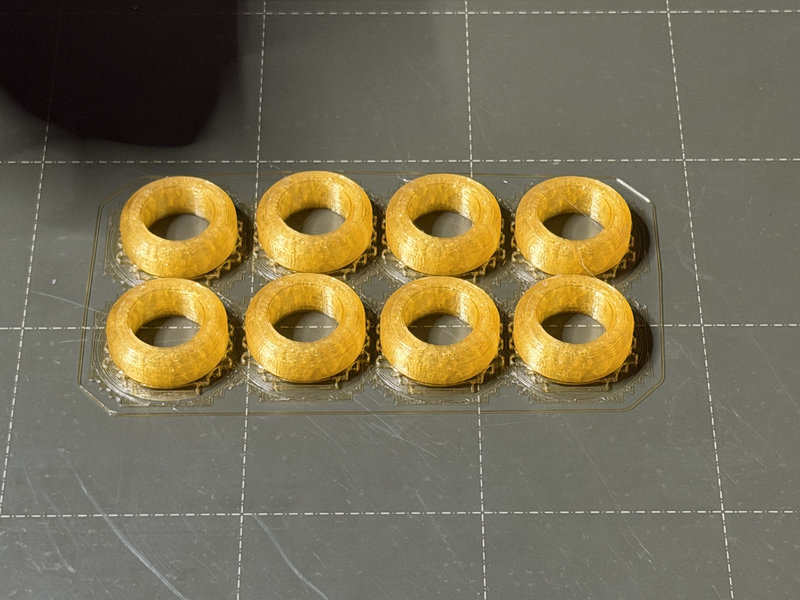
Smaller parts like the casing for the bearings were also designed and 3D printed.
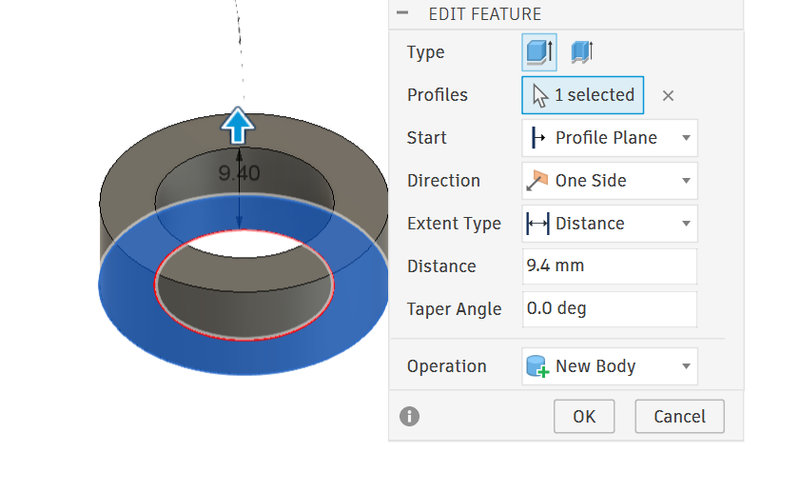 |
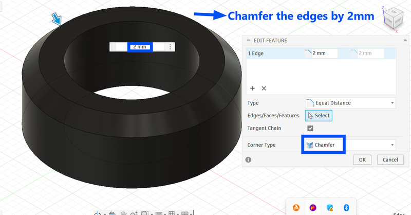 |
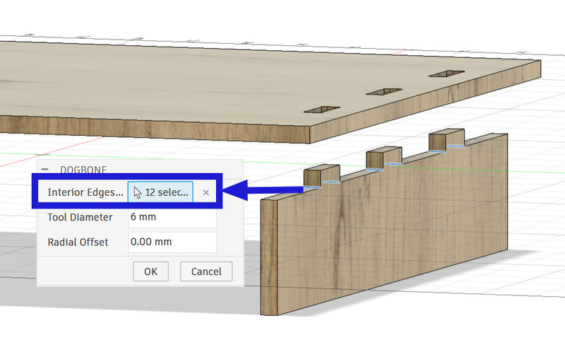
The next task was to design the base of the pen plotter.
Here are the steps that were followed:
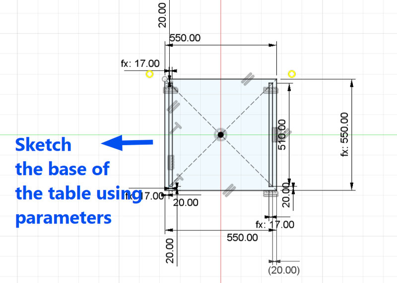
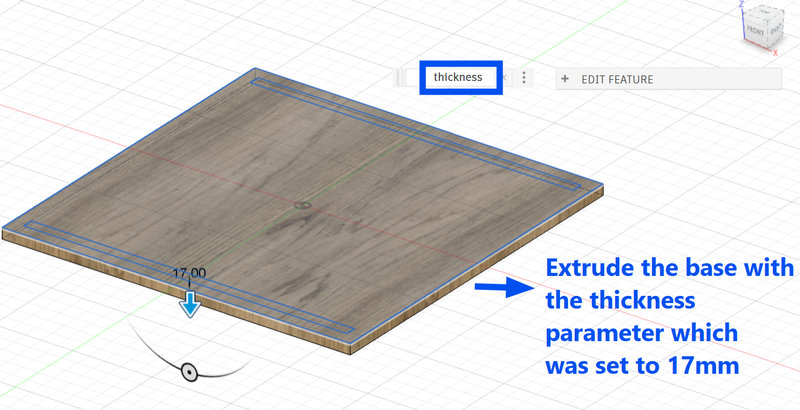
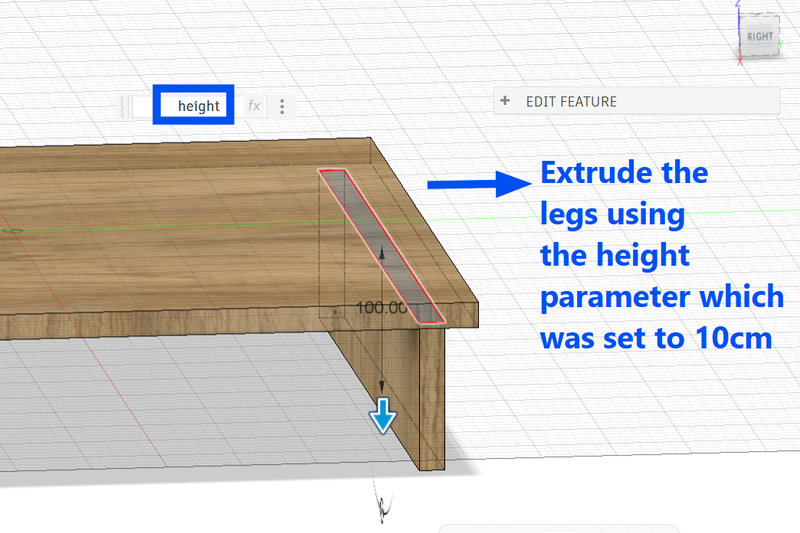
Dogbones were also created for the slots.
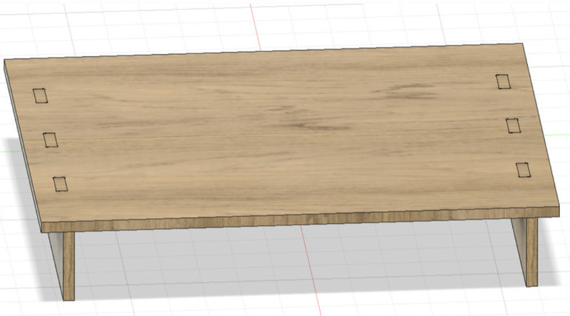
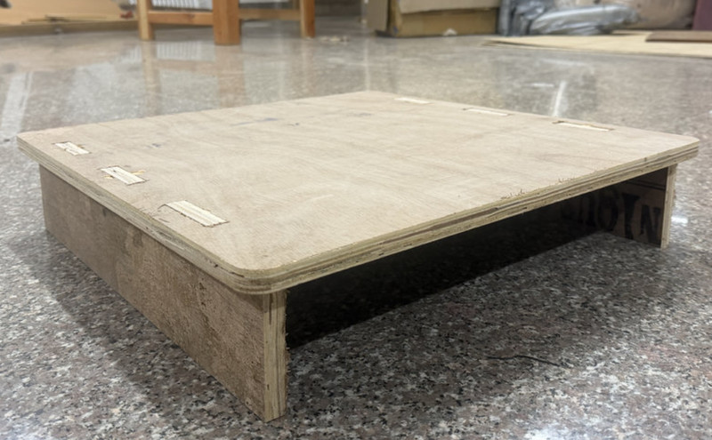
This is the final look of the table:
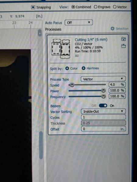
Cutting
It took about 40 minutes to finish cutting everything.
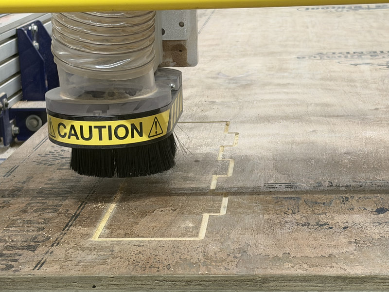
Here is the final look after assembling!!! 😄
This was our frist trial 🤗😁
Final Video
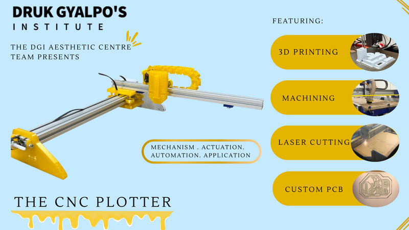
Poster
That is all for this week.