Machine Week — Mechanical & Machine Design

For machine week, our group designed and built a 3-axis CNC solder paste dispenser for circuit board fabrication. Each team member took responsibility for a different section of the machine. I worked on the Z-axis and the tool head — specifically, the solder paste dispensing mechanism.

Assignment Requirements

Mechanical Design (Part 1 of 2):

Group Assignment:

Individual Assignment:

Machine Design (Part 2 of 2):

Group Assignment:

Individual Assignment:

Machine Overview

Assembled 3-axis CNC solder paste dispenser

Completed 3-axis CNC solder paste dispenser machine

Our machine is a 3-axis CNC solder paste dispenser designed to automate the application of solder paste onto circuit boards. Instead of manually applying paste with a stencil or by hand, this machine uses G-code to precisely deposit solder paste at each pad location on a PCB.

How It Works

The machine moves a syringe filled with solder paste along the X, Y, and Z axes. The X and Y axes position the syringe over the correct pad on the board, while the Z-axis lowers the tip to the surface. A separate stepper motor with a lead screw pushes down on the syringe plunger to dispense a controlled amount of paste.

This was a team project where each member was responsible for a different axis. My contribution focused on the Z-axis (vertical movement) and the tool head (solder paste dispensing mechanism).

My Individual Contribution — Z-Axis & Tool Head

3D Model — Full Assembly

Explore the complete assembly of the tool head and Z-axis in 3D. Click and drag to rotate, scroll to zoom:

Interactive 3D model - Click and drag to rotate, scroll to zoom

Design Files

Download the full-resolution design files to view, modify, or 3D print the parts yourself:

📥 Download STL 📥 Download Fusion 360 File

My responsibility was the Z-axis and the tool head — figuring out how to dispense solder paste in a controlled, repeatable way and integrating that mechanism into the Z-axis of the machine.

Syringe dispenser design inspiration

Design inspiration for the syringe dispensing mechanism

The first idea was straightforward: use a syringe to hold the solder paste and find a way to push the plunger down mechanically. I briefly considered a pneumatic system — using air pressure to push the paste out — but that would have required a compressor, regulators, valves, and tubing, adding a lot of complexity and extra parts to the build.

Instead, I went with a lead screw driven by a stepper motor. The stepper turns the lead screw, which translates rotational motion into linear motion, pushing the syringe plunger down at a controlled rate. This gives precise control over how much paste is dispensed — you can control the volume by controlling the number of steps.

Why Lead Screw + Stepper?

  • Precision: Stepper motors move in discrete steps, so you get fine control over how far the plunger moves and how much paste comes out
  • Simplicity: No air compressor, no valves, no tubing — just a motor, a lead screw, and a mount
  • Repeatability: Same number of steps = same amount of paste every time
  • Integration: The lead screw mechanism fits naturally into the Z-axis assembly

Lower Plate Design

I began by designing the lower plate for the tool head. The plate uses four 8mm × 100mm stainless steel rods:

  • 2 support rods — provide structural rigidity for the assembly
  • 2 guide rods — the plunger pusher slides along these to press down on the syringe

Syringe Holder & Clamp

I designed a slot in the lower plate that fits the specific syringe we're using for solder paste. The syringe drops into the slot and is held in place by a clamp. Precision here was critical — even the smallest design flaw could cause major issues down the road when you're trying to precisely dispense measured amounts of paste. The tolerance for the syringe slot had to be perfect so it slips into the exact same position every time, ensuring repeatable dispensing.

Syringe Pusher

I modeled a custom syringe pusher that moves up and down on the guide rods. Originally I was going to connect it to the existing syringe plunger, but I decided to make a new one from scratch — it's much easier to get a precise fit that way rather than trying to clamp an existing plunger in perfectly.

I spent a lot of time dialing in the tolerances until I got a perfect snap-in fit with the solder paste syringe. Even being slightly off could mess up the whole machine — the pads on a PCB are tiny, and applying solder paste to them has to be exact.

Bottom & Top Plate Details

On the bottom plate, I added:

  • Holes to connect the aluminum extrusion (Z-axis mount)
  • Slots for the rails to connect — these are in the same positions on the top plate for alignment
  • A clamp for the syringe to lock it firmly in place

Dispensing Control

We considered adding a force sensor to detect how much pressure is being applied to the syringe, but after thinking it through, we decided against it. Instead, we're programming the machine to push out the desired amount by running the stepper motor at a slow, controlled speed. The machine will also push a small amount of paste out before it starts printing to prime the syringe and eliminate air gaps.

Versatility

This tool head isn't limited to solder paste — it could be used for anything that comes in a syringe and needs to be laid out precisely. The difference is that our code and motor speeds will be specifically tuned and tested for the viscosity of the solder paste we're using.

Assembly Chain

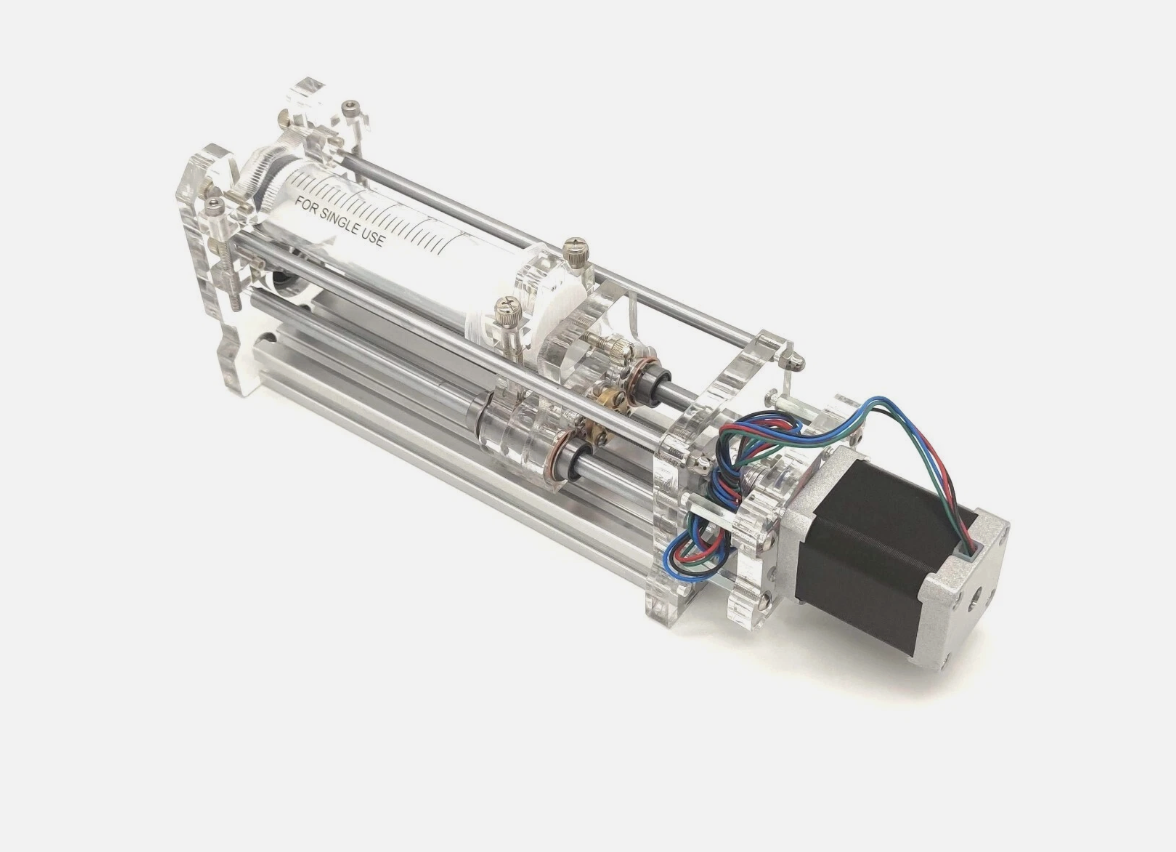
The assembly chain goes: tool head (syringe + dispense stepper) → Z-axis → Y-axis on the CNC gantry. My tool head mounts to the Z-axis, which then connects to the Y-axis carriage on the gantry that the rest of the team designed.

Z-Axis Mechanism

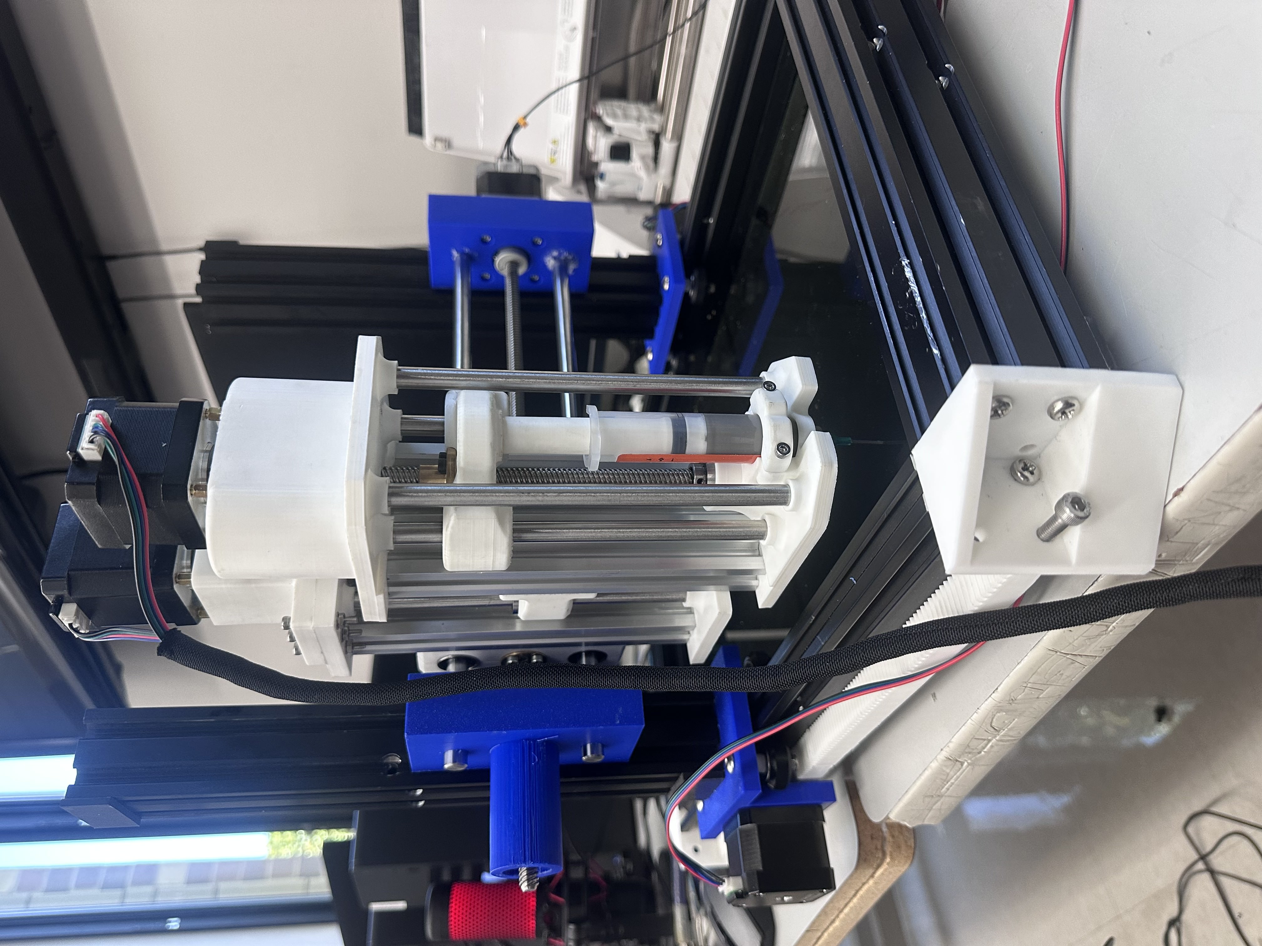
The Z-axis sits between two pieces of extruded aluminum, using two guide rods with linear bearings for smooth vertical travel and the same T8 lead screw as the tool head. The stepper motor turns the lead screw, which moves the entire tool head assembly up and down.

All the stepper motors on this machine are NEMA 17s, but for the Z-axis I needed a larger NEMA 17 — the Z-axis has to lift the entire weight of the tool head. The guide rods and bearings don't carry any of the load; they only add rigidity and keep the carriage aligned. All the lifting force comes from the stepper motor and lead screw.

The Z-axis is configured the same way as the tool head — using extruded aluminum on the back for mounting. It works perfectly for vertical movement (up and down), and the mechanism is now fully functional and tested.

Stepper Motor Mounting — Redesigned

One of the harder parts was finding a strong way to mount the stepper motors, because they had to sit higher than the top plate. I had to design a mounting solution that held the motors securely above the plate while keeping everything aligned with the lead screw below.

I had a lot of trouble assembling the first motor mount design, so I redesigned it to make assembly much easier. The new mount is simpler and faster to put together. Unfortunately, during assembly I tightened one of the parts too much and it snapped — a piece is now stuck in the stepper motor. But it's still pretty sturdy and will definitely work for what we need. The motor is secure and the Z-axis moves smoothly.

Limit Switch Placement Decision

I considered adding a limit switch to the Z-axis for homing and zeroing, but I realized that wouldn't work well for this machine. The reason: we can swap out different syringe tips that have different lengths. If the limit switch was on the Z-axis, the machine wouldn't be able to zero correctly depending on which tool head tip is installed.

Instead, the limit switch should be mounted on the tool bed (the surface where the PCB sits). That way, the machine can always zero to the bed surface regardless of which tip is being used. This makes the machine more versatile and ensures accurate Z-height calibration every time.

Mounting to the Y-Axis

For connecting the Z-axis to the Y-axis, I told the team member responsible for the Y-axis that he would need to design his mount so the Z-axis could attach to the extruded aluminum — similar to how I mounted the tool head to the Z-axis using the aluminum extrusion. This kept the mounting approach consistent across the machine.

I designed the Y-axis mount to attach to the backside of the extruded aluminum. Initially, we had issues getting it connected — the parts weren't lining up correctly. After I did some fixing and adjustments to his part, I was able to get it mounted up perfectly. The connection is now solid and the Z-axis moves smoothly along the Y-axis.

Cable Management

To keep everything clean and protect the wiring, I routed the motor cables through a cord protector (cable management sleeve). This gives the machine a much cleaner look and prevents the cables from getting caught in moving parts or snagging on the frame during operation. Proper cable management is critical on a CNC machine — loose wires can cause shorts, get pinched, or interfere with motion.

Aluminum Extrusion Mount

For the back of the tool head, I sourced an extruded aluminum profile from Amazon. This is what mounts the entire tool head assembly to the Z-axis. I sketched out the cross-section of the aluminum extrusion in Fusion 360 and extruded it to my desired length to model it accurately in the assembly.

Extruded aluminum cross-section modeled in Fusion 360

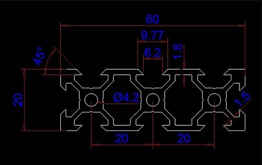
Extruded aluminum cross-section sketched in Fusion 360

Weight Considerations

The Z-axis assembly adds a lot of weight. I had to communicate to the rest of the team early on that the X and Y axes would need to be designed to hold significant weight without putting strain on their stepper motors. Getting that right early was important — if the frame can't handle the load, nothing else matters.

Fastening & Assembly

For the 3D printed components, I used heat-set inserts to create strong, reusable threaded connections in the PLA parts. For the aluminum extrusion, I used a tap to cut threads into the inside of the extrusion channels, allowing bolts to thread directly into the aluminum for a solid mechanical connection.

Purchased Parts

Part Quantity Size
T8 Lead Screw with Copper Coupler Bearing 2 D8mm × L150mm
Stainless Steel Round Rods 6 (3 packs of 2) 8mm × 150mm
Aluminum Extrusion 2 150mm / 5.9"

Additional Parts

These parts I either already had or were available in the lab:

  • NEMA 17 stepper motors
  • Solder paste syringe
  • Linear motion rod bearings / sliders
  • Heat-set inserts
  • Aluminum extrusion T-nuts
  • Miscellaneous nuts and bolts

3D Printing

All the custom parts were 3D printed on a Bambu A1 using Bambu generic white PLA, sliced with Bambu Studio:

  • Printer: Bambu A1
  • Material: Bambu generic white PLA
  • Infill: 20–30% gyroid
  • Wall thickness: Increased from default for added rigidity
  • Quality: Fine quality preset for tighter tolerances and better surface finish

Ideally I would have printed the final parts in PETG for better strength and durability, but I didn't have the time to source it and reprint everything. Instead, I increased the wall thickness and used 20–30% gyroid infill on the PLA to make the parts as strong as possible.

Useful Links