5 Axis Robot Arm
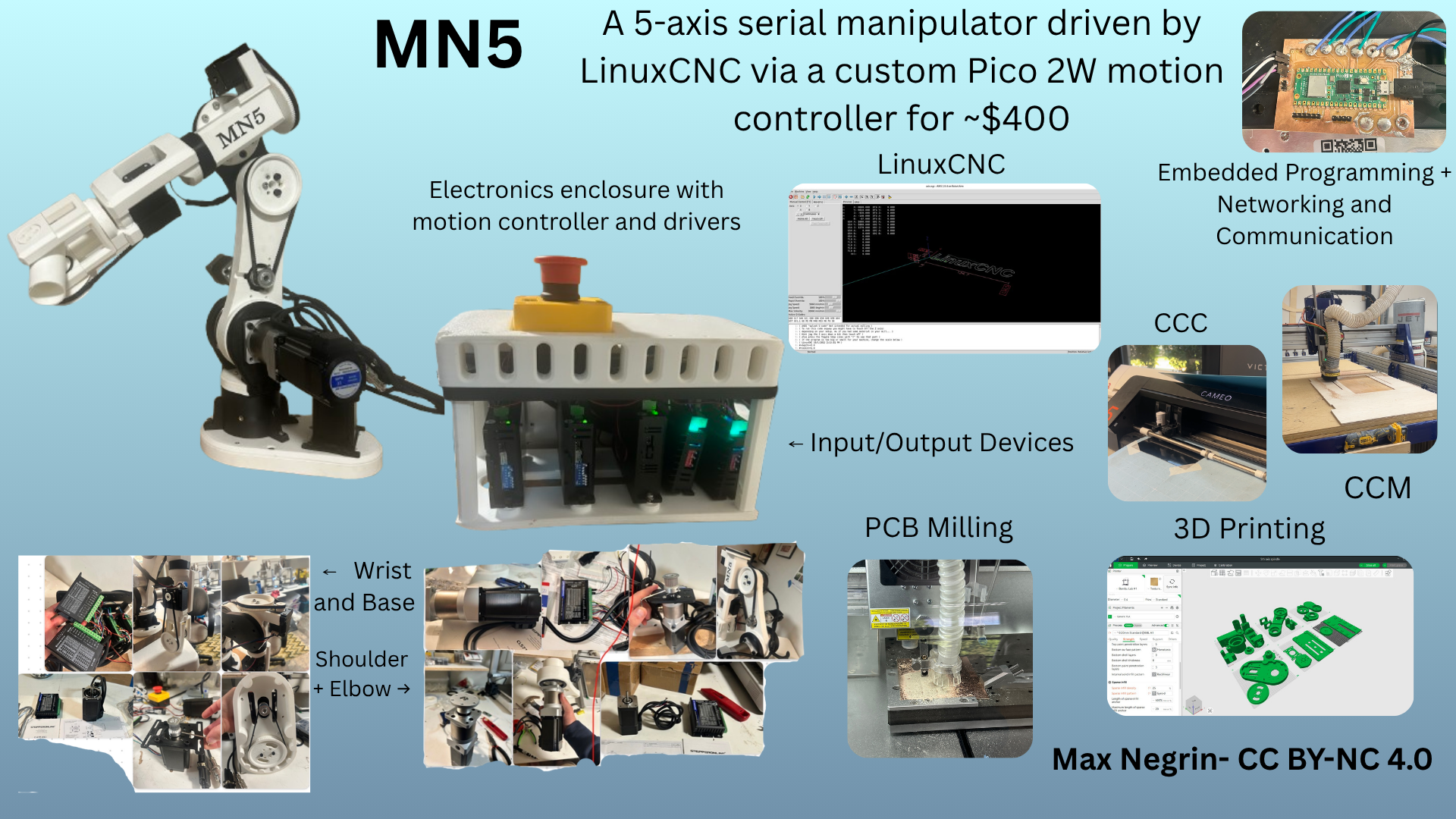
My final project is a 5 axis serial manipulator arm. It uses stepper motors with gearboxes and belt reductions for greater torque, and 3d printed links for the majority of the structural components. It is controlled by LinuxCNC running the genserkins module on a desktop computer sending commands via a custom program to a Pico 2W running custom firmware, which then calculates the number of steps needed to reach the commanded position given the steps per rotation. LinuxCNC is an incredibly powerful (and equally frustrating) software, and it enables complete control over the arm: you can synchronize each axis to run complex gcode, trace patterns in the air, and repeat any pattern you command. It was among the hardest parts of this build process, but by far the most rewarding. For the arm, I used the following weeks:
Not my Work
I borrowed this guy's motor mount bracket + belt tensioner for the wrist joints, after realizing that my current method for tensioning belts is extremely silly. I did modify it a little, but barely. It helps to tension the belts on joints 3 and 4.
I also downloaded ALL of the stepper motor + gearbox combos from the official Stepperonline website. You can find links to the downloads in the BOM for each respective component. This is a purely cosmetic thing, as it is just so the 3d model of the arm looks more complete.
Week 2: CAD week
As most of the project is 3D printed, I made heavy use of CAD. I used Fusion 360 to completely model the entire arm, with interactive joints (including stepper motors, which are obviously not 3d printed). Here is the model of the arm:
Week 3:
I created a sticker to better the looks of the final product. More documentation is below.
Week 4: Embedded Programming
For this week, I made use of a Raspberry Pi Pico 2W as the microcontroller, soldered to a PCB breakout board for easier interfacing with the electrical components of the arm.
Week 5: 3D Printing
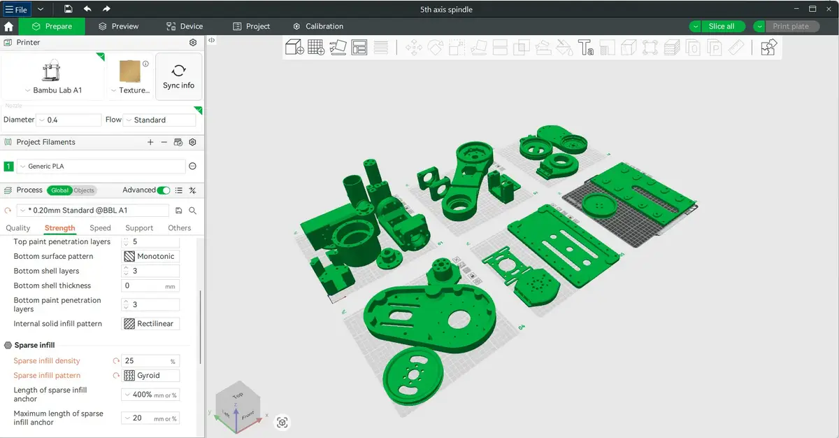
As a majority of the components of the arm are 3D printed, this week is very important to the final product. I printed each part of the arm individually on my and the lab's Bambu A1s, with 8 wall loops and 25% gyroid infill for all parts above the shoulder arm mount. All parts including and below the shoulder arm mount are 16 wall loops and 100% infill, as they support the weight of the entire arm + payload, and they are not being supported by any motors, so their weight is not important.
Week 6: Electronics Design AND Week 8: Electronics Production
To tidy routing between the stepper drivers and the Raspberry Pi Pico 2 W, I laid out a small interface board. Each driver gets three landing pads—STEP, DIR, and ENABLE for a possible software e-stop. Three 2-pin headers pair limit switches to GPIO and GND. I also added 1×4 and 1×6 2.54 mm headers for extras (driver ALARM, future wrist limit, and other GPIO).
In KiCad, signal pads use the 3 mm mechanical solder-pad footprint; headers use standard 2.54 mm footprints. The large pads are easier to land stranded wire from the drivers than single header pins. Copper geometry is 0.5 mm on the pad nets and 0.25 mm on the header signals, with a flooded GND pour tying driver returns to logic ground.
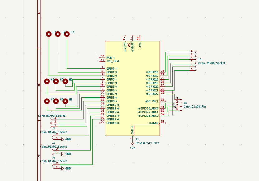
Schematic of the interface PCB.
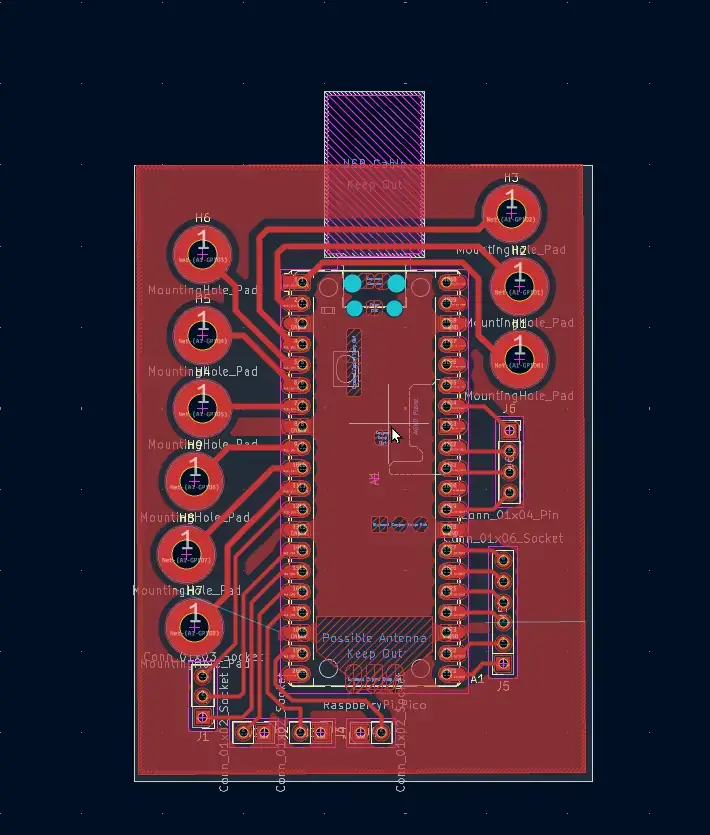
Board layout with pours and traces.
Design Rules Check before fab:
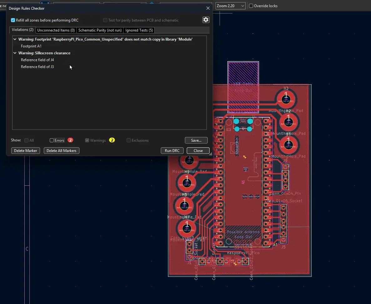
DRC results—no unresolved errors before export.
From KiCad I exported Gerbers and drill files, then moved to the Carvera workstation and built toolpaths from saved profiles.
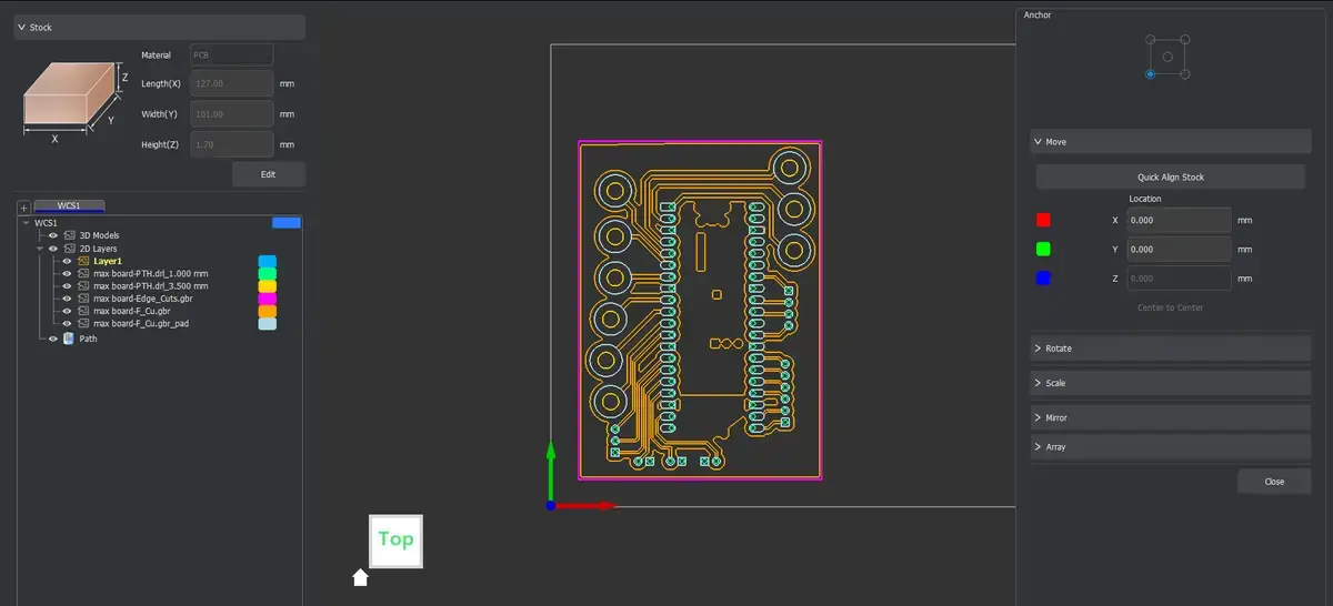
Carvera CAM profiles for the board.
Four operations: a long isolation/engraving pass for traces and pad outlines, two drill cycles (headers vs wire pads), and an outer contour to release the board from stock. The pad drills ended up too small for the wire gauge I wanted, so I plan to solder those leads on the copper side instead of threading through the holes.
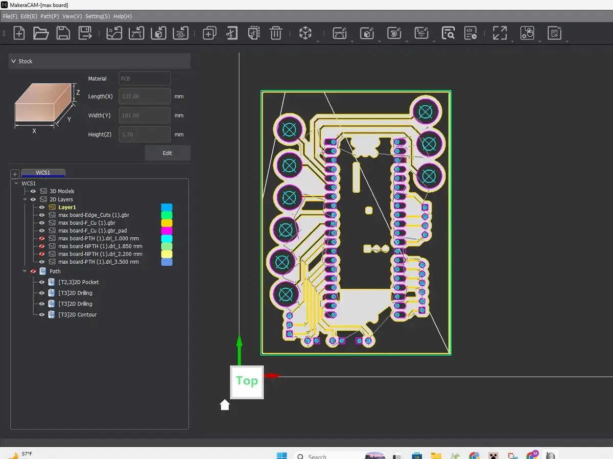
Toolpath preview in the milling software.
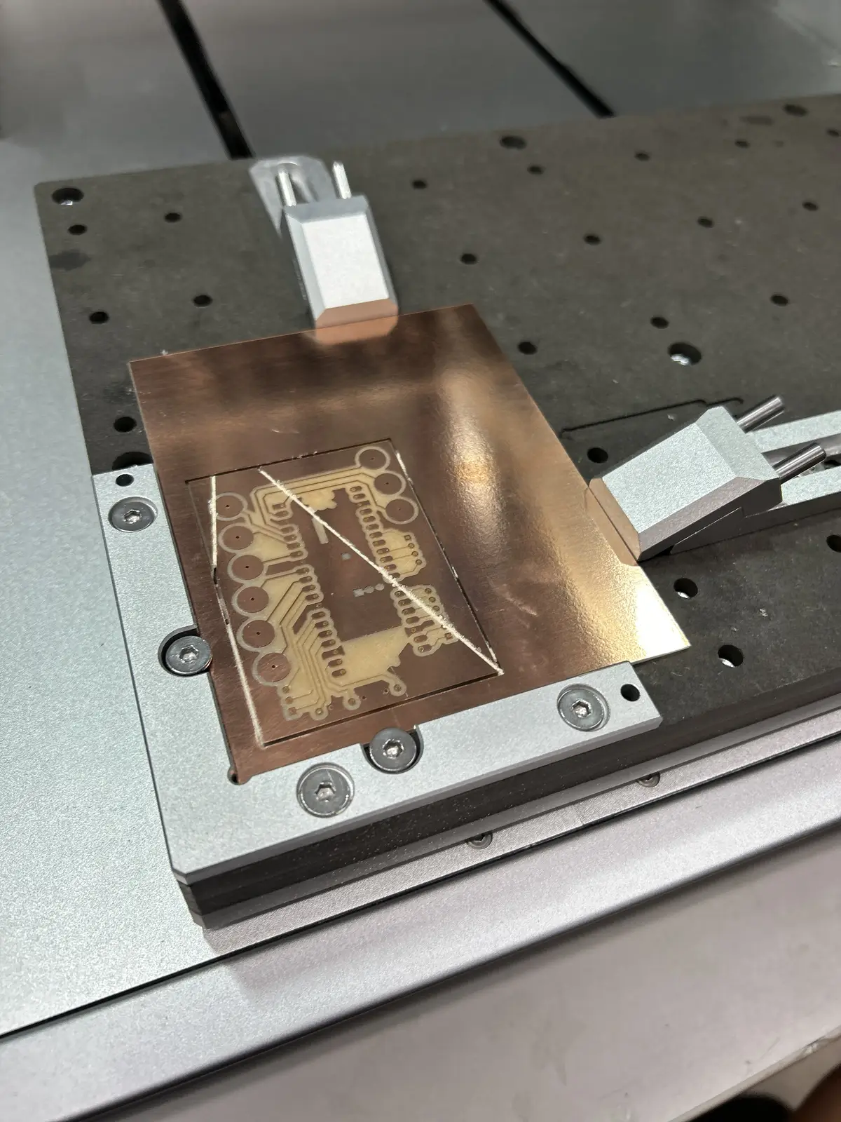
The first article looked good after machining.
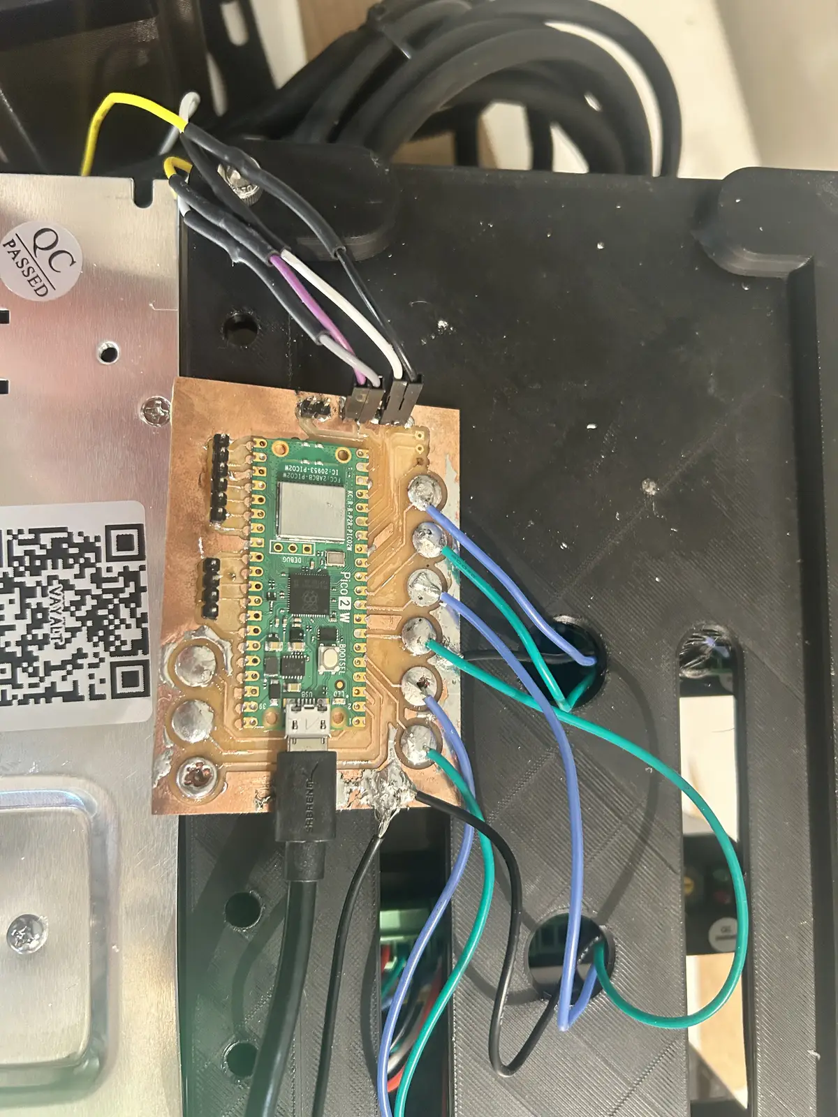
And then I soldered the signal wires and the microcontroller to the board, which now lives in its final position.
Week 7:
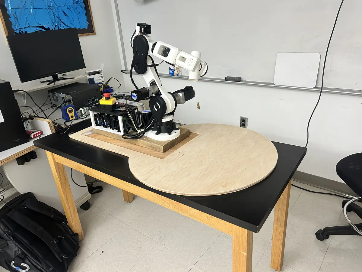
I used the shopbot to mill a plywood sheet that serves as the work space for the arm. More documentation on this process/result is below.
Week 10: Output Devices
This week is another essential week to the integrity of the project: the motors are what creates movement in the arm. I use screw terminal stepper drivers, with the elbow down being from Stepperonline, and the rest being from Amazon. You can refer to my BOM for more info. The drivers pull from my 24v PSU with an E-Stop in between to break the circuit. While it is an immature location for an estop (it should be tied to the enable pins), I chose this location to be able to completely shutoff power in case of emergency (electrical shocks, fire). The drivers take step/dir in from the Pico 2W and fire the corresponding coils. For more precise control, I have encoders on the elbow and shoulder (the motor drivers handle position feedback) and use 1600 steps per rotation for each joint.
Week 11: Networking and Communication
For communication between the Pico 2W and LinuxCNC on the RPI4, I had the use claude to create a custom serial protocol, which includes joint angles and E-Stop/Machine Power status. You can find the repo (on my personal github) here. Please read the software documentation here.
Week 14: Interface Programming
To actually visualize the robot arm's movement, I used claude to generate a vismach python script, initialized automatically by LinuxCNC. It takes ASCII stls, repositions them given different translation functions, and finally links their rotation origins to the actual arm's joint position. You can find the vismach file on my repo here
Week 15: System Integration
On this page, I document how each individual part (the drivers, arm, and computer) connects to each other to form the complete system.
The Robot Arm
I am not quite sure why I decided to pursue this project. There is really no need, and I am not really solving any existing problem. I guess I just thought it was cool. It is a serial 5 axis robotic manipulator, inspired by Annin Robotic's AR4.
BOM
Here is the BOM for the robot arm. You can download it in .ODS Format at this link
Project Timeline
A Gantt chart is a horizontal bar chart that maps the tasks of a project against a timeline, showing when each task starts, how long it lasts, and how it overlaps with the others. Its purpose here is to lay out the full path from mid-March through the June 10 presentation so I can see at a glance which phases are done, which are in progress, and how the remaining documentation and deliverables stack against the deadline.
gantt
    title Robot Arm Final Project — Path to June 10 Presentation
    dateFormat  YYYY-MM-DD
    axisFormat  %b %d

    section CAD & Design
    Finalize Fusion 360 model        :done, cad1, 2026-03-16, 14d
    Design revisions / part remakes  :done, cad2, 2026-03-30, 35d

    section 3D Printing
    Base & turret parts              :done, p1, 2026-03-16, 10d
    Shoulder parts                   :done, p2, 2026-03-23, 10d
    Elbow parts                      :done, p3, 2026-04-06, 10d
    Wrist parts                      :done, p4, 2026-04-20, 10d
    Reprints / iterations            :done, p5, 2026-04-20, 21d

    section Mechanical Assembly
    Base turret + tapered bearings   :done, m1, 2026-03-23, 7d
    Shoulder joint + gearbox         :done, m2, 2026-04-01, 10d
    Elbow joint + bearings           :done, m3, 2026-04-13, 7d
    Wrist joints                     :done, m4, 2026-04-27, 7d

    section Electronics
    PCB schematic + layout (KiCad)   :done, e1, 2026-04-06, 5d
    PCB milling on Carvera           :done, e2, 2026-04-13, 3d
    Wiring drivers + PSU + E-stop    :done, e3, 2026-04-20, 7d
    Limit switch install             :done, e4, 2026-04-27, 4d

    section Firmware & Software
    Pico 2W firmware (step/dir)      :done, s1, 2026-04-20, 10d
    LinuxCNC + genserkins setup      :done, s2, 2026-04-27, 14d
    Serial protocol (Pico ↔ RPi)     :done, s3, 2026-05-04, 7d
    Vismach visualization script     :done, s4, 2026-05-11, 7d

    section Integration & Tuning
    System integration               :done, i1, 2026-05-11, 10d
    Motion tuning + repeatability    :active, i2, 2026-05-18, 12d
    Payload & gcode testing          :i3, 2026-05-28, 7d

    section Documentation
    Process section (photos)         :active, d3, 2026-05-25, 6d
    Evaluation / results writeup     :d4, 2026-05-30, 4d
    Fix placeholders, typos, links   :d5, 2026-05-26, 4d
    Hero photos of finished arm      :d6, 2026-06-02, 2d

    section Final Deliverables
    1-minute presentation video      :d7, 2026-06-04, 3d
    1920x1080 slide PNG              :d8, 2026-06-06, 1d
    Final review pass                :d9, 2026-06-08, 2d
    Presentation                     :milestone, m, 2026-06-10, 0d
Licensing
This work is licensed under a Creative Commons Attribution-NonCommercial 4.0 International License. You are free to share, remix, and alter this project for any non-profit or educational purpose as long as you provide proper attribution. For any commercial use or intent to sell this work, you must obtain explicit written permission from the creator.
The Problems
What does it do?
It is a 5 axis robot arm with around a 500g payload (although I am working to increase that). You can upload gcode via linuxcnc and have it run different patterns.
Who's done what beforehand?
The only project I could find that was close to mine was this machine week project. I would like to add, however, that they used an existing design, while mine I created from the ground up (in the humblest way possible). I also found this, but it was unfortunately what I was trying to avoid: he used servos.
What did you design?
I designed the entire assembly in fusion, save for the drivers. That was one of my regrets, that I didnt create a custom stepper board and instead simply bought them. I also created the simple interface PCB.
What sources did you use?
I used claude code a significant amount for the software side. I also took a lot of inspiration from the AR4 robot arm project.
What materials and components were used?
The structure was mostly PLA printed on my lab's Bambu A1s. I used belts for power transmission, a significant number of heat inserts, M5 screws to hold everything together, wire + heatshrink for signals, gearboxes, steppers, stepper drivers. For the base, I used a chunk of wood that has been sitting outside for most of my childhood, and a 24v power supply.
Where did they come from?
All of the CNC-related things (drivers, steppers, PSU) came from Stepperonline, and all the other miscellaneous things came from Amazon. I was able to find small things like heat inserts from the lab.
How much did they cost?
The project was roughly $400 in total. I see this as a win, as other projects of similar scale and capability cost ~$2000>.
What parts and systems were made?
I made the mechanical systems, the driver housing, and the interface PCB.
What processes were used?
3D printing: For almost all of the physical parts of the project Milling: for the PCB.
What questions were answered?
Going in, I had three big open questions, and the project answered all of them:
- Can I run real-time motion control on cheap, lab-grade hardware? Yes — but not on a Raspberry Pi 4. The Pi couldn't solve the inverse kinematics inside the servo period, so I moved to a $70 used desktop running Debian + PREEMPT_RT, which handles it without breaking a sweat.
- Can LinuxCNC's genserkins actually drive a custom 5-axis arm? Yes. It defaults to 6-axis arms, but once I had the DH parameters right it solved the kinematics for my 5-axis build and let me world-jog the end effector through 3D space.
- Can I get clean, jitter-free step generation off a Pico? Yes — by offloading step timing to the Pico's PIO state machines instead of the main CPU, so the pulses stay evenly spaced no matter what the processor is doing.
What worked? What didn't?
Worked:
- The full control chain — LinuxCNC → genserkins → HAL → Pico → PIO → drivers — produces smooth, coordinated five-axis motion.
- The closed-loop shoulder and elbow joints hold position under load without missing steps.
- The HTD-3M belt reductions and the 3D-printed structure are rigid enough for the ~500 g payload.
- The VisMach model tracks the real arm, which is genuinely useful for spotting trouble given there are no encoders on the controller side.
Didn't (or could be better):
- The Pi 4 was a dead end — I lost time before accepting it couldn't keep up with the kinematics.
- Hand-homing with no limit switches is imprecise; repeatability suffers because the zero position is set by eye.
- The shoulder gearbox backlash was closer to a full degree than the advertised 0.25°, and that play shows up out at the wrist.
- The elbow moves slowly, because a mis-measured belt order forced a ~4:1 reduction I hadn't planned for.
- Communicating over USB instead of Ethernet caps how fast I can stream commands to the Pico.
- With no encoder feedback reaching the controller, the system is effectively open-loop — if a belt slips, LinuxCNC never finds out.
How was it evaluated?
Can it produce smooth motion from point to point utilizing each joint indepedently? Can it move from point to point with high repeatability?
What are the implications?
Multi-Axis manipulators can be DIYed at home, to obviously amatuer levels of success.
The Process
Firstly, I started out with the 3d modeling. I really just dove into this without any real sense of direction or what the final product should look like (or even how it would work) but I managed to figure it out as I went. The modeling process took me roughly 20 hours total, as a conservative estimate, so I will not be discussing that in depth. If you are reading this, I am assuming you know how to extrude a sketch. Here is a sped-up video of the timeline, from start to finish, of the arm in Fusion:
Then, I had to assemble it. I used M5 screws with heat inserts for all of the places where parts connect. For the base joint, I used tapered roller bearings, an extremely overkill but equally effective option. I also used a tapered roller bearing/thrust roller bearing combo for the elbow, which produced smooth motion. For the shoulder, I used large 90x70mm bearings to support the link and a metal flange hub to connect the motor. The wrist joints both use 45x32mm bearings, which I had laying around from the cycloidal drive project.
I used a significant amount of 3D printing for my project. I used 8 wall loops and 25% infill for a majority of the project, excluding the base components, which were 100% infill. Each part laid out in Bambu Slicer:
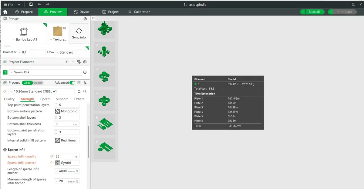
And it took around 3d days for printing (even more, realistically, as this is assuming everything is printed at the lower range of the infill/wall loop values I used for this project) and 2.5 kg of filament. I certainly used around twice as much as that in the end, including all of the iterations and temporary placeholder parts created because I wanted to see it work before needing to wait for the part to arrive.
The Hardware
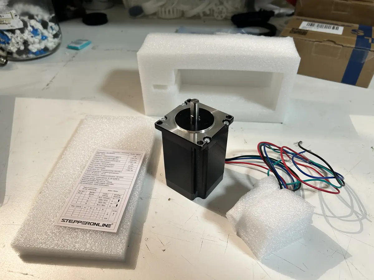
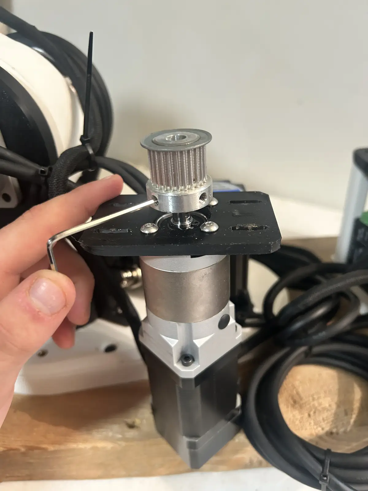
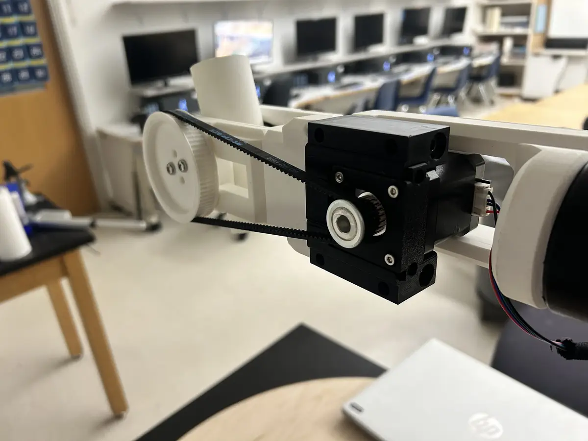
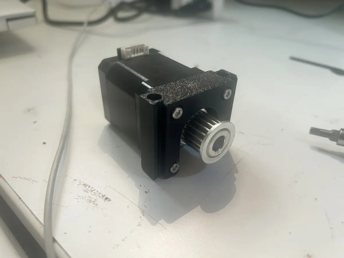
And now for an overview of the parts used in this project. I used the HTD 3M standard for all belts in this project, selected for its high torque ratings and deep teeth which help to minimize slipping. The HTD 3M belt standard is a type of synchronous timing belt with a 3 mm tooth pitch, designed for precise power transmission in compact mechanical systems. Its rounded tooth profile reduces backlash and improves load‑carrying capability, making it popular in robotics, 3D printers, and small machinery. Originally, I was going to use a longer belt for the base and a shorter belt for the elbow, but that all changed when I increased the length of the shoulder arm (to the maximum size my build plate would allow), so I ended up just using the same size belt for each joint (447mm long). Now, for the motors and drivers. For the base, I selected a 2NM NEMA 23, which I chose over a NEMA 17 with a gearbox, as the nema 23 has more torque at the same speed, which is exactly what I wanted. It has a 20t aluminum pulley driving a 105t pulley on the base.
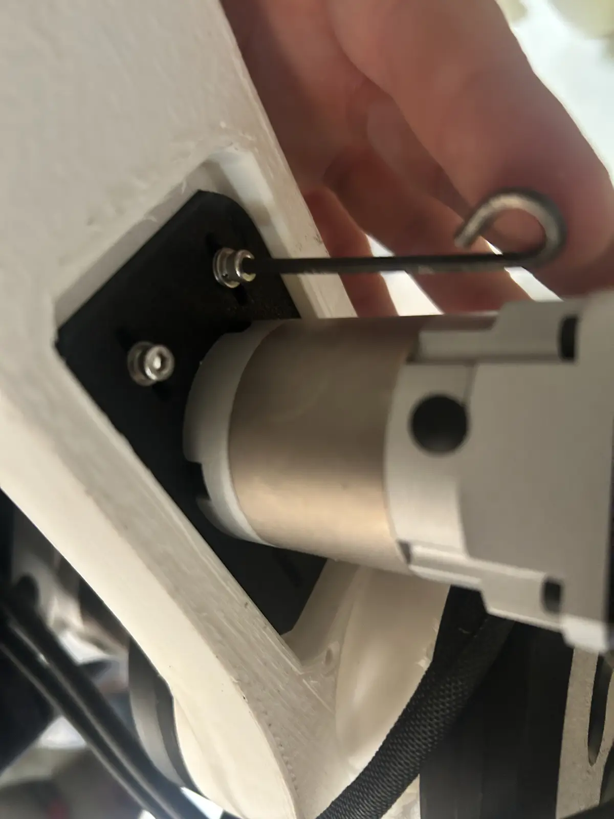
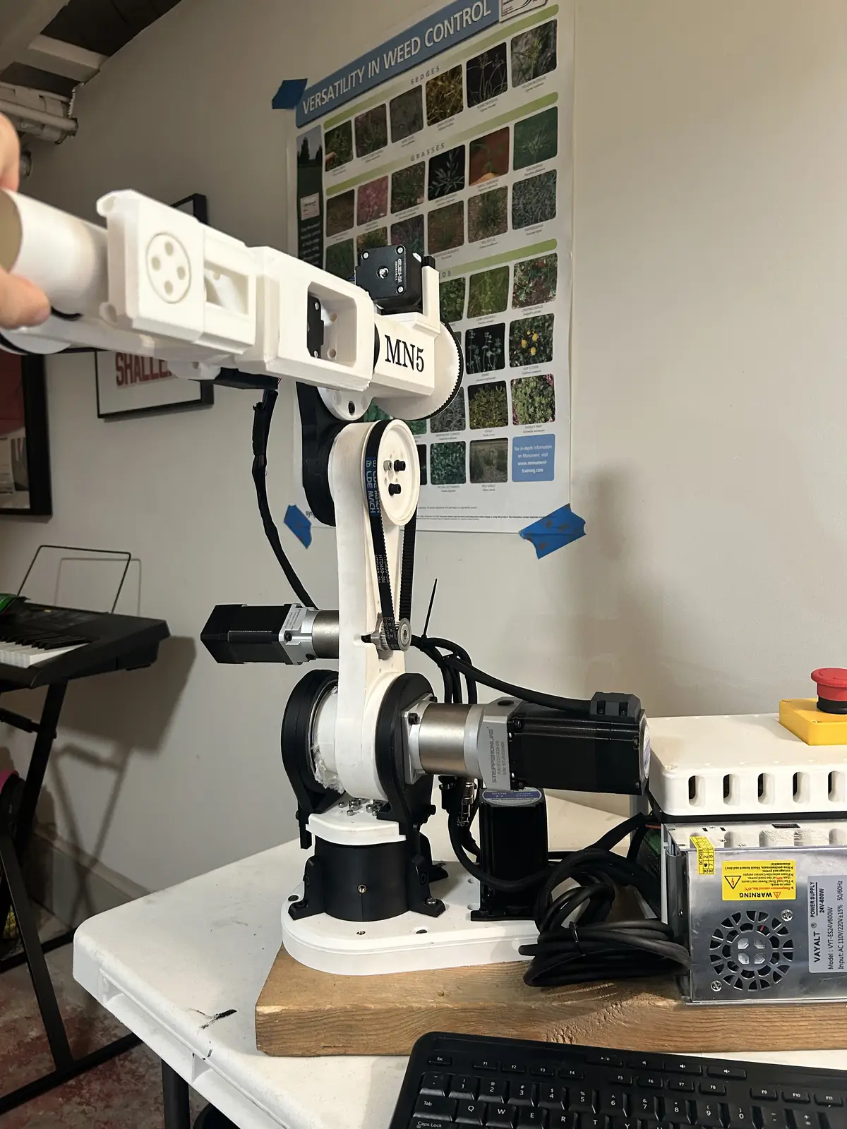
It also has a custom made motor bracket, with slots to adjust the distance between the pulley's centers to tension the belt.
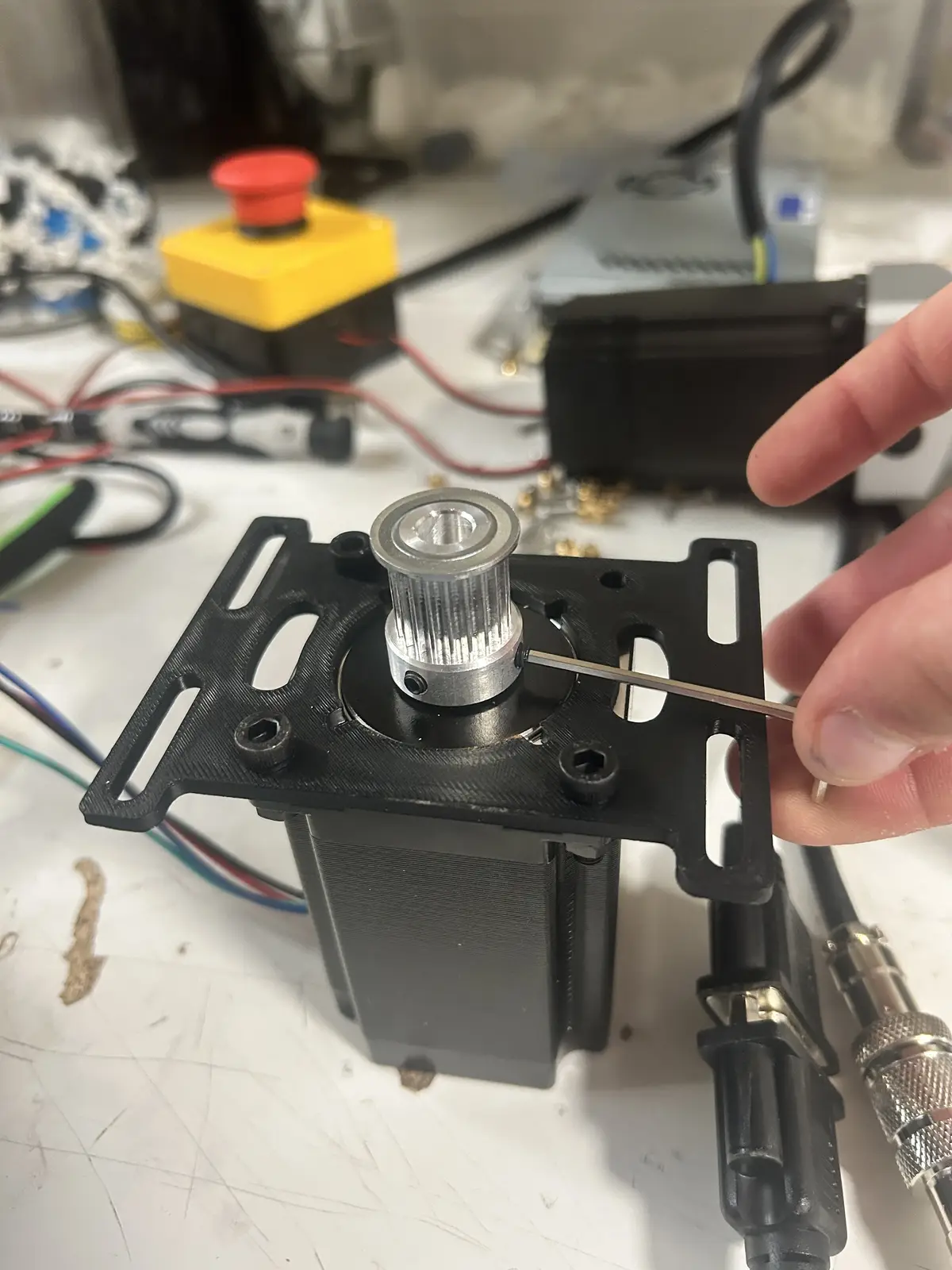
And in its final location:
And this is what tensioning the belt looks like:
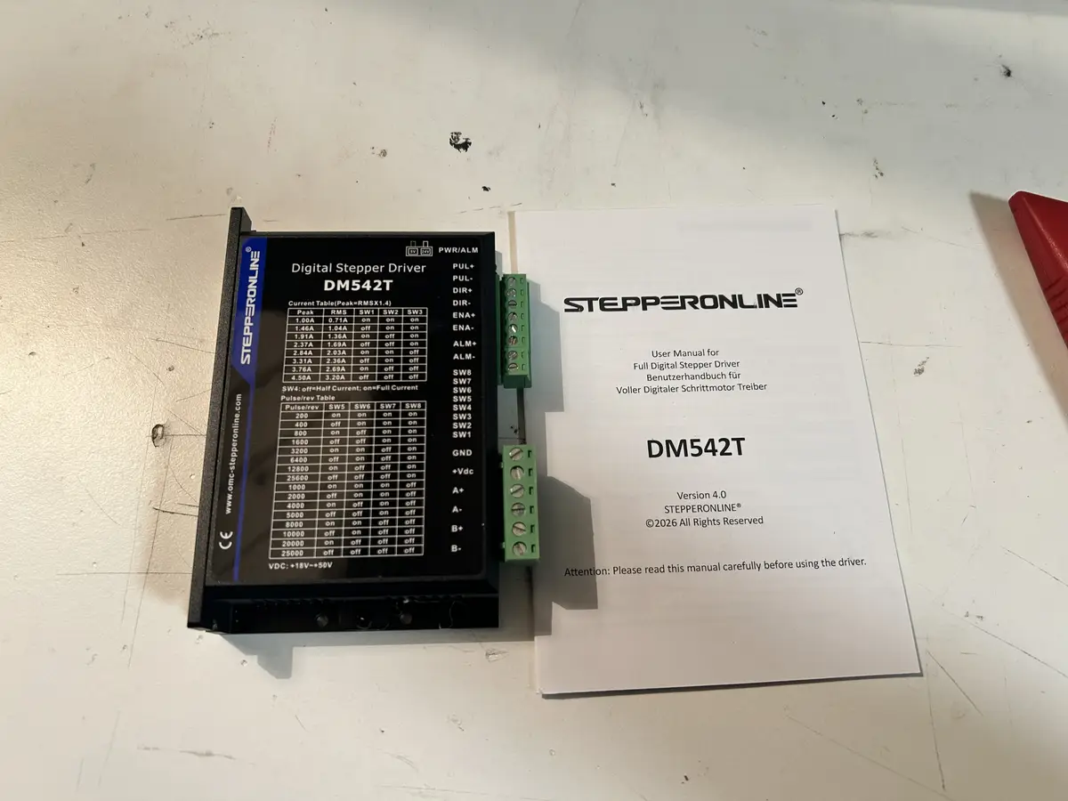
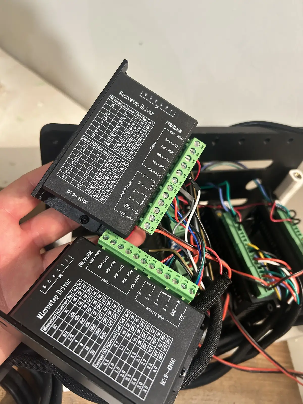
It is paired with a DM542T driver from stepperonline, and is set to 1/4 microstepping, which you can configure using the table printed to the driver and the DIP switches on the side. The driver is nothing special (unlike for the elbow and shoulder), besides the fact that it supports microstepping. So, all I had to do was screw the phase wires of the motor into the corresponding terminals on the driver.
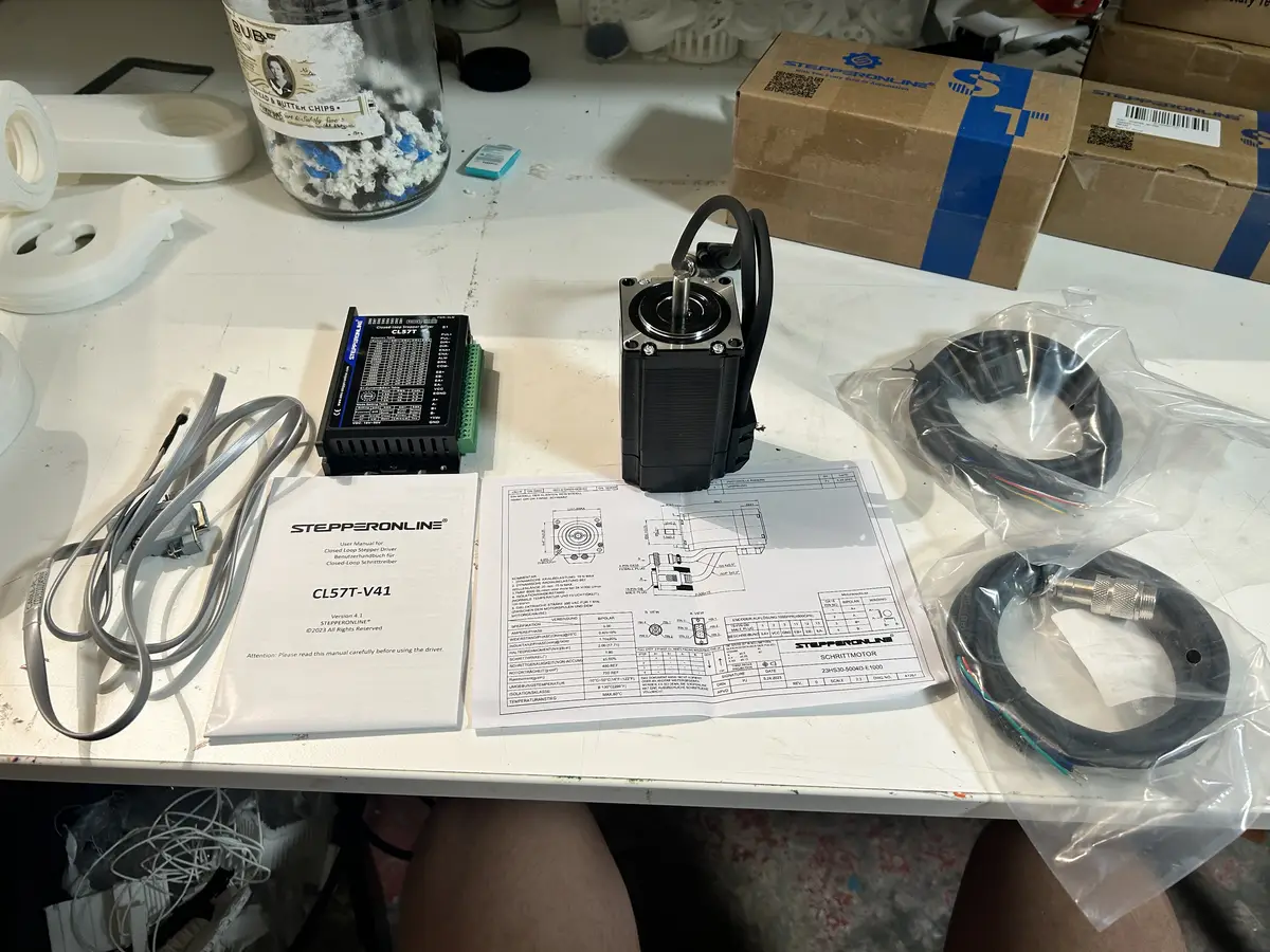
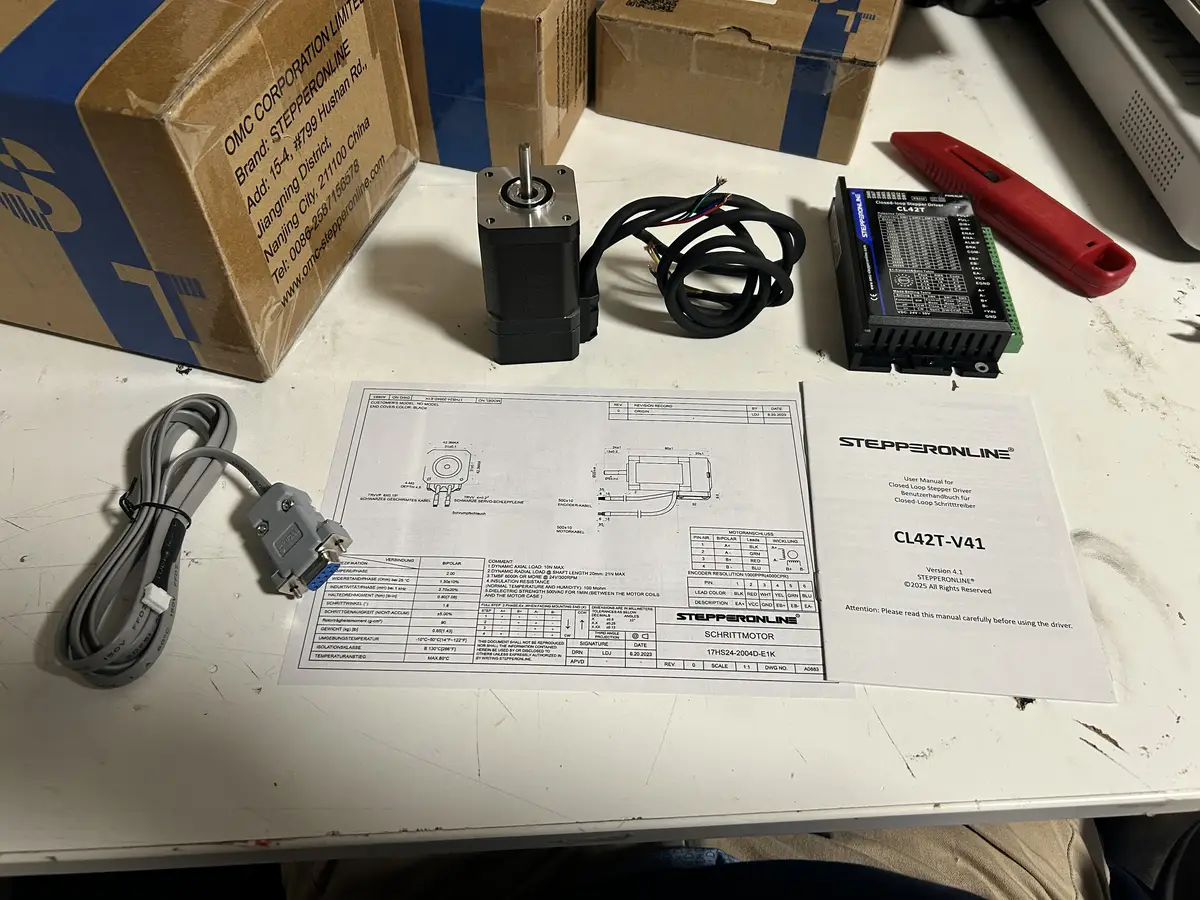
The shoulder is one of the two special joints, in that it has an encoder and is a closed loop joint. It is also a 2NM NEMA 23 motor, driven by Stepperonline's CL52T closed loop stepper driver. The driver takes the encoder's signals as an input and processes them + applies the position change automatically, without needing to waste MCU IO.
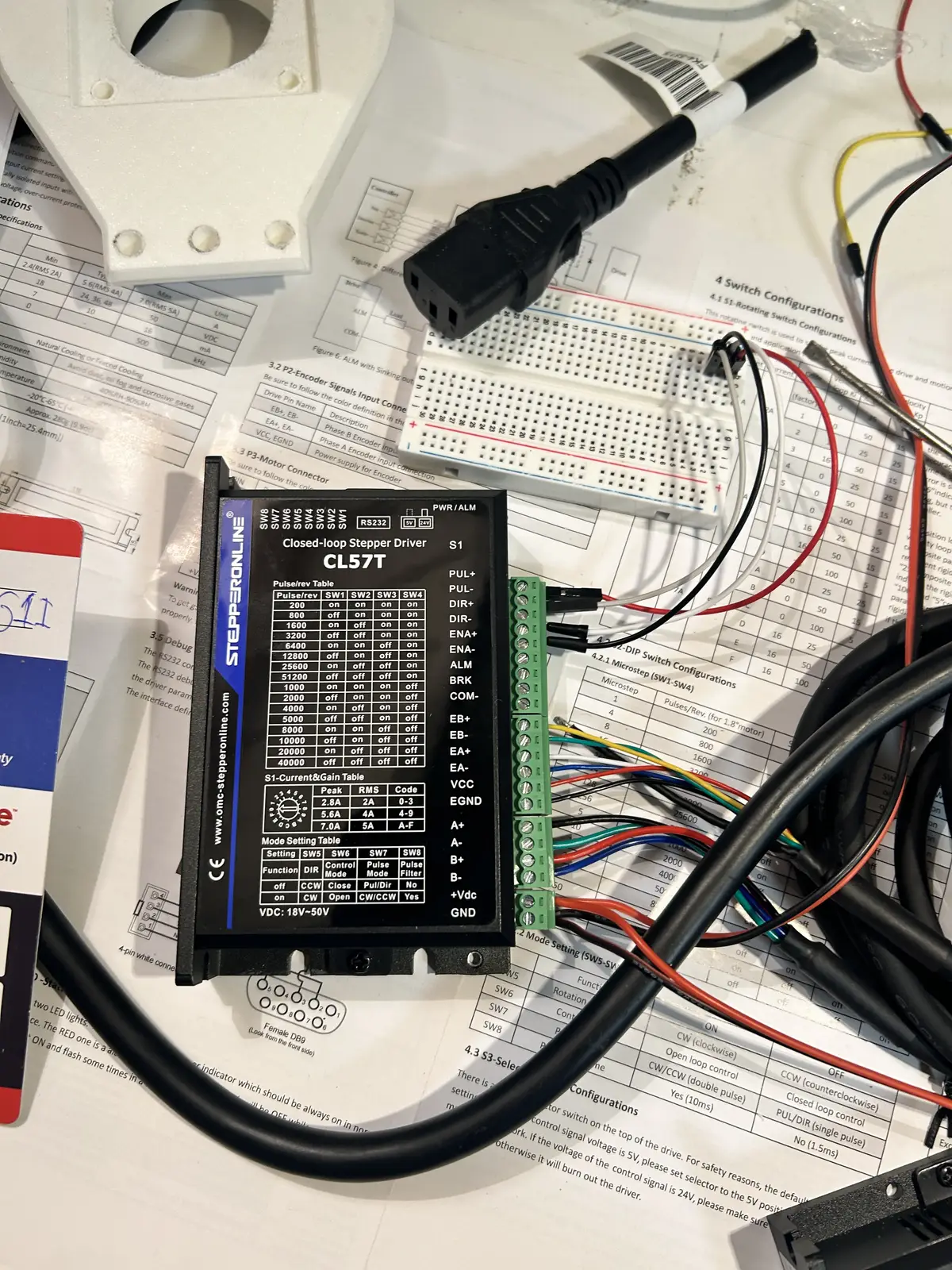
As you can see, it has inputs for, and is connected to, an encoder, which it automatically corrects for. This driver's microstepping is still handled by DIP switches on the side, but the current is handled by a rotary switch, whose values you can find in this document. Mine is set to 5.6 Amps, which is .6 amps outside of the recommended operating range, but I do not need to worry about overheating as the closed loop system works to only apply power at very high load.
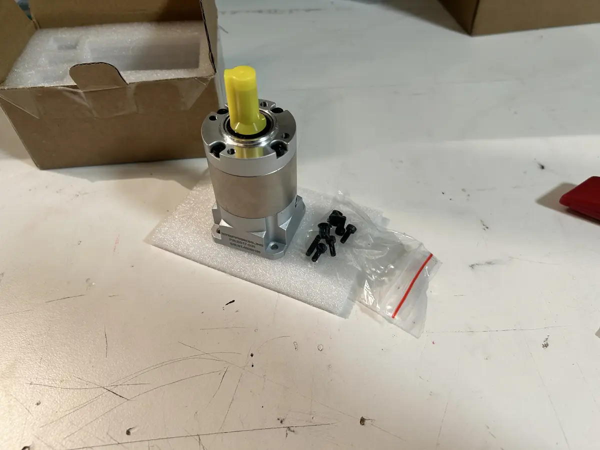
The shoulder motor is equiped with a 20:1 planetary gearbox reducer, which turns the quick rotation of the stepper into high torque, but slow, motion. It is advertised as having a backlash of around 15 arc-minutes, which translates to .25 degrees (this was not true, I could observe at least a degree of backlash in the system). Backlash is the small amount of play or looseness between mechanical parts shows up as a delay before motion fully transfers.
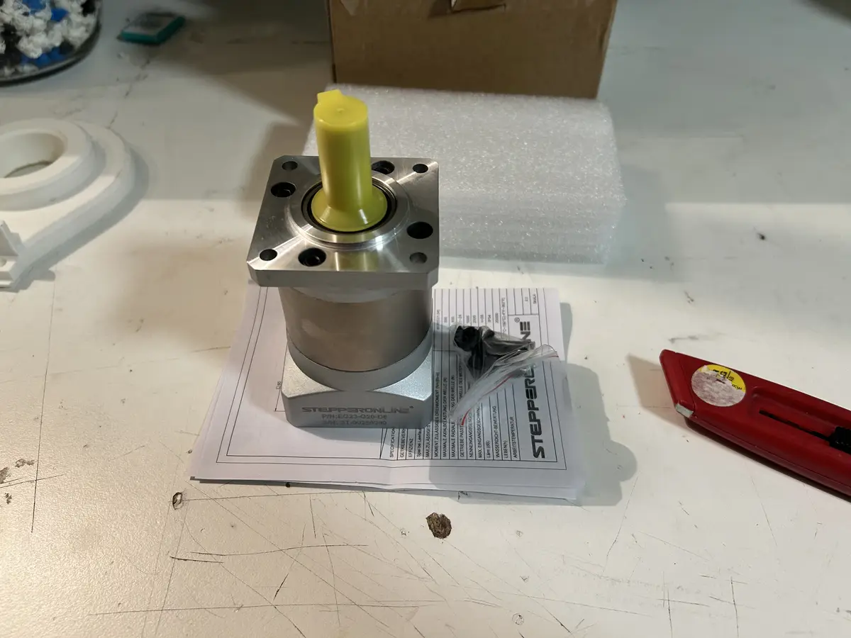
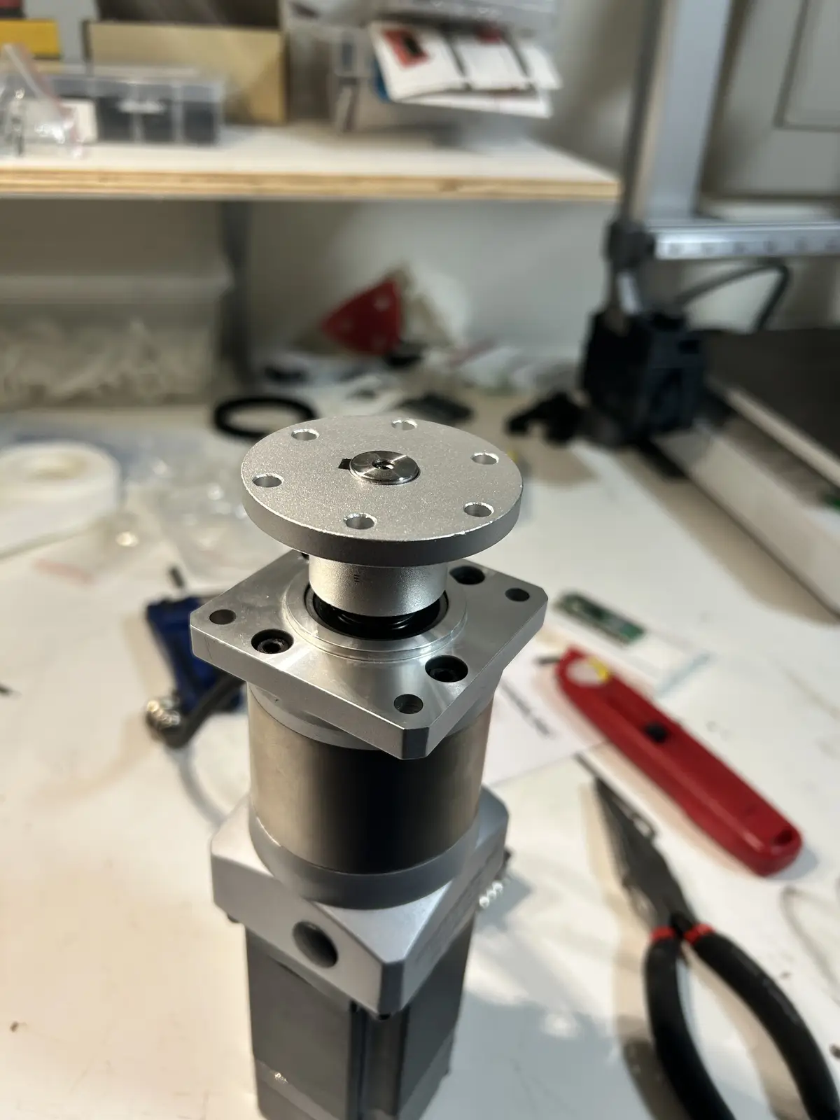
The gearbox fits on to the stepper motor with a collar, which you can tighten via holes in the sides. It is screwed to the motor with the holes on the base, which you can see above, using M5 screws and bolts. To connect to the shoulder link, I have an aluminum flange hub that is tightened to the shaft using a keyway and set screws. The flange hub is first screwed down to the shoulder link, then the motor + gearbox is screwed to the motor mount, and then finally the flange hub + link is set onto the gearbox's shaft.
I chose this setup because the shoulder will experience the highest load out of all the joints, and having both a powerful motor and closed loop feedback meant this joint would still remain accurate even under heavy load. And making it direct-drive means I would not have to suffer from belts not being able to hold the high torque and slipping.
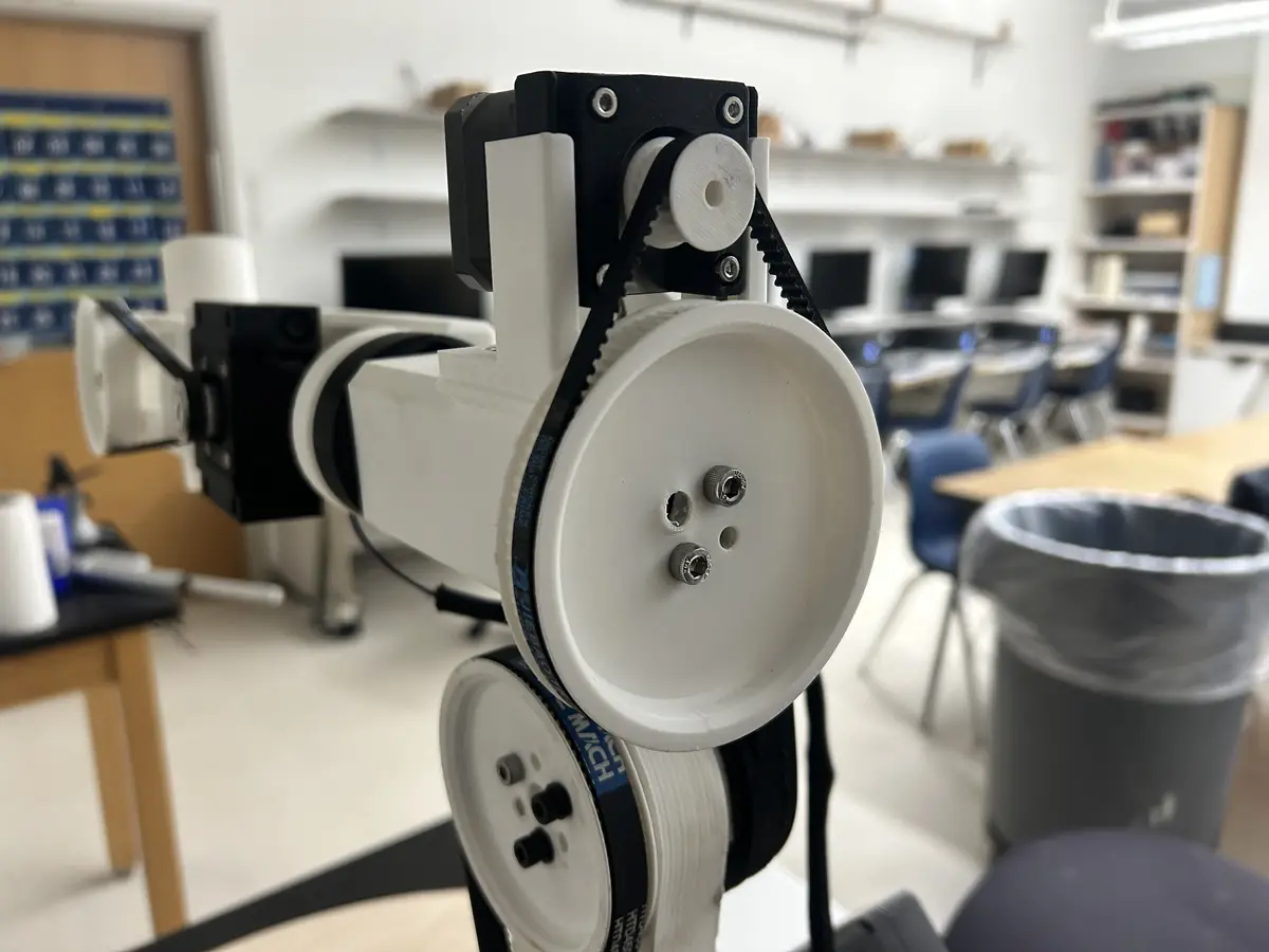
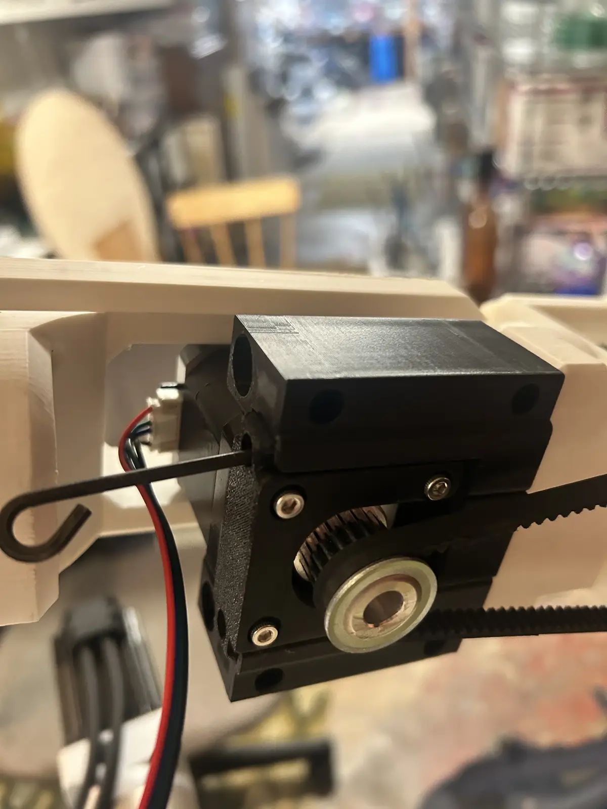
The elbow motor setup is extremely similar to the shoulder, except for the fact that the motor is smaller. It uses a .8NM NEMA 17 stepper with a 20:1 gearbox and a roughly 4:1 belt reduction. The belt reduction was a result of faulty measuring causing me to order the wrong sized belt, which led to me using one of the bases' much longer belts. It turned out fine though, but the joint does move pretty slowly. It also has an encoder on it, as it is the second most loaded joint of the arm, so it needs to be able to carry weight without missing steps. Like the shoulder, the encoder position feedback is also handled by the drivers themselves.
And the elbow's gearbox
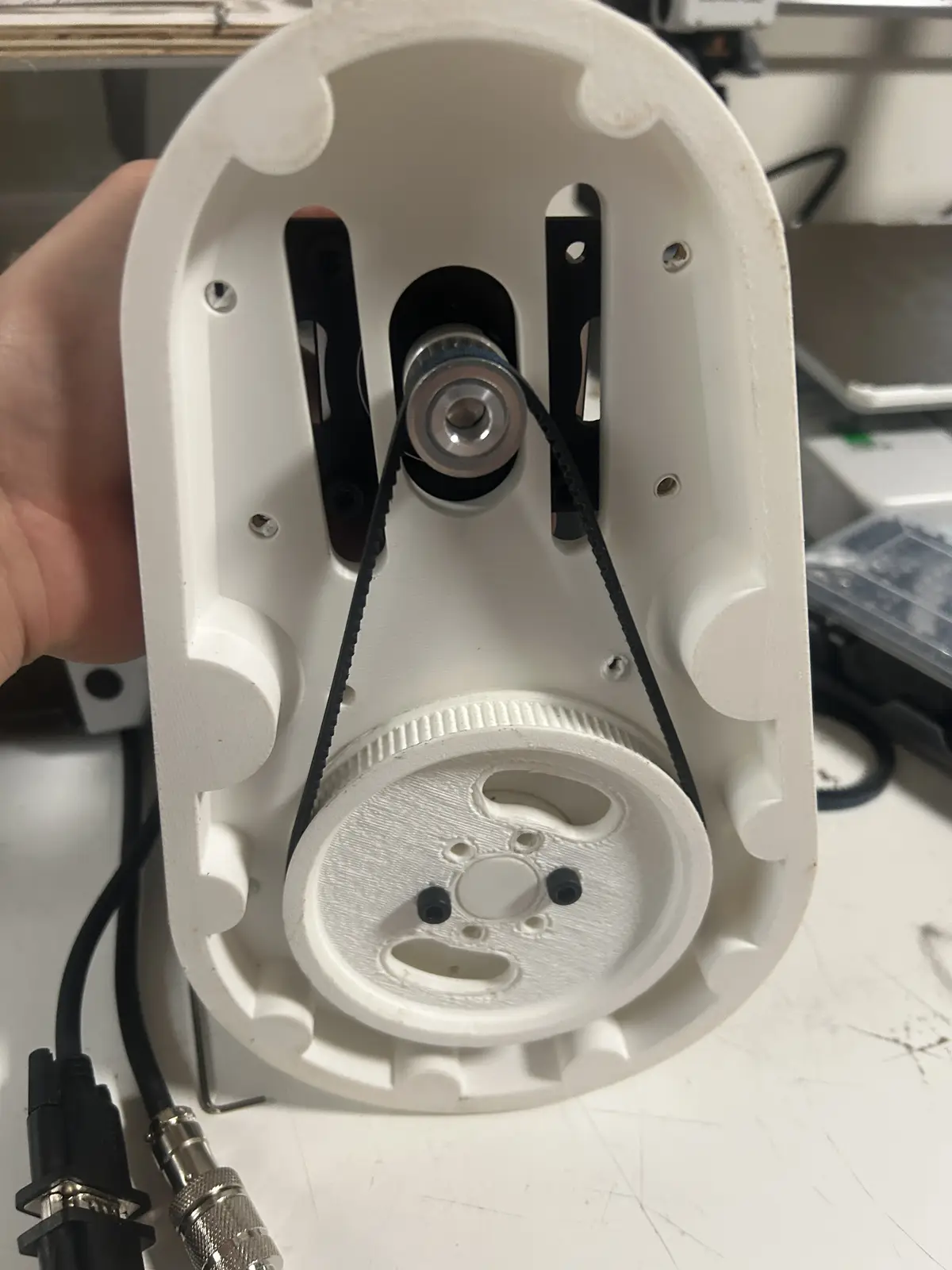
It uses a 20t driver pulley driving an 80t pulley, with a custom 3d printed mounting bracket that lets me tension the belt without any other mechanical components.
And you tension it very similarly to the base, by manually holding it down and tightenting the mounting screws
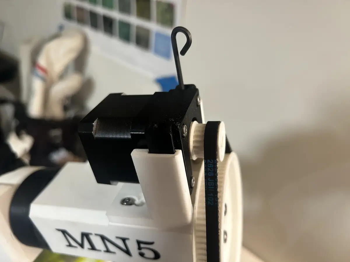
For the wrist joints, they both use 0.5NM NEMA 17s that I found from the lab, paired with two TB6600 motor drivers, which were the absolute cheapest options.
The rotating joint has a 20t pulley driving a 95t pulley:
And the other wrist joint, which uses a 20t driving pulley with a 50t driven pulley:
Both of these joints use the same belt tensioning system which I found from this Printables link. Both of the motors are screwed into a bracket like this:
With holes at the tops for long m3 screws which serve as the tensioning part. These brackets are then set into matching mounts, where you can tighten the above mentioned screws to tension the belt.
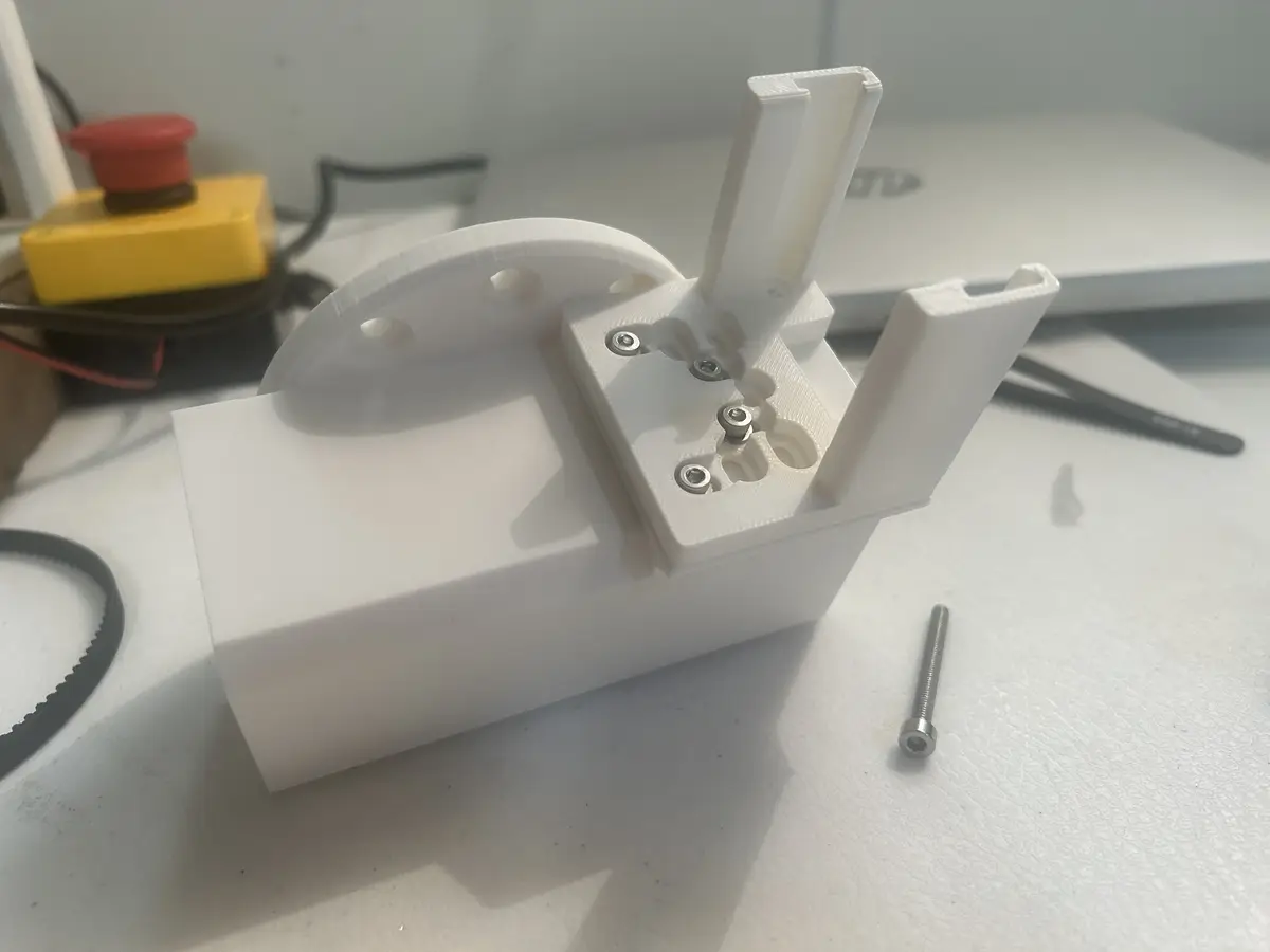
And then you set the motor with its bracket into the holder, put the belt over the driver and driven pulleys, and tighten the screws to tension the belt:
Electronics
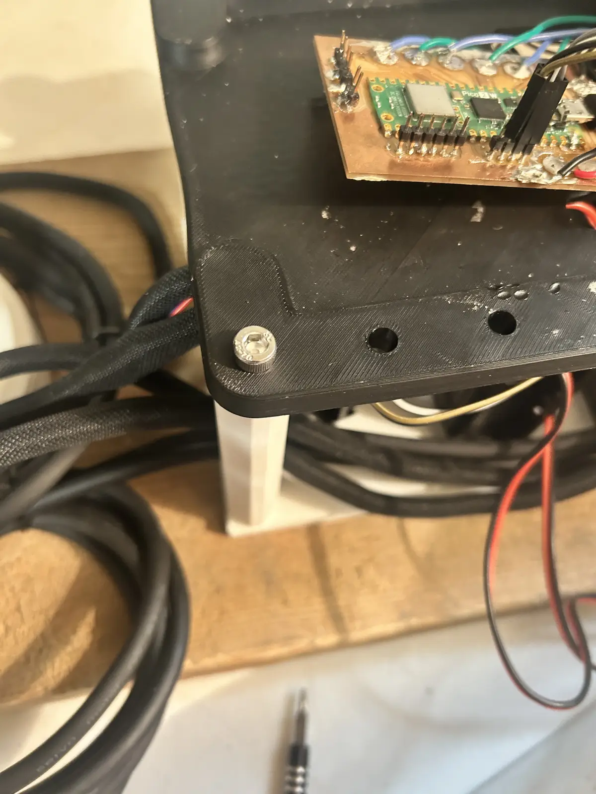
In this section, I will talk about the drivers, the estop, and the organizational wiring of the robot arm. Firstly, I created a 3d printed enclosure to mount all of the drivers in Fusion, which I then 3d printed using 6 wall loops and 15% rectangular infill. Each driver is screwed down, with both closed loop drivers using m5, and the three normal drivers using m3.
The enclosure has a base plate with heat inserts, where the drivers are screwed down, then four pillars (fastened from the top and bottom, they have inserts on both sides.)
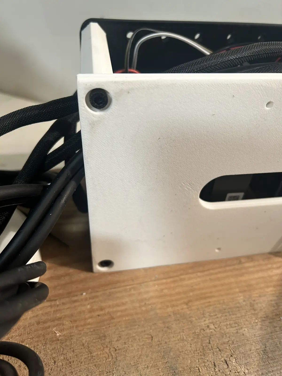
And it is screwed in from the top as well.
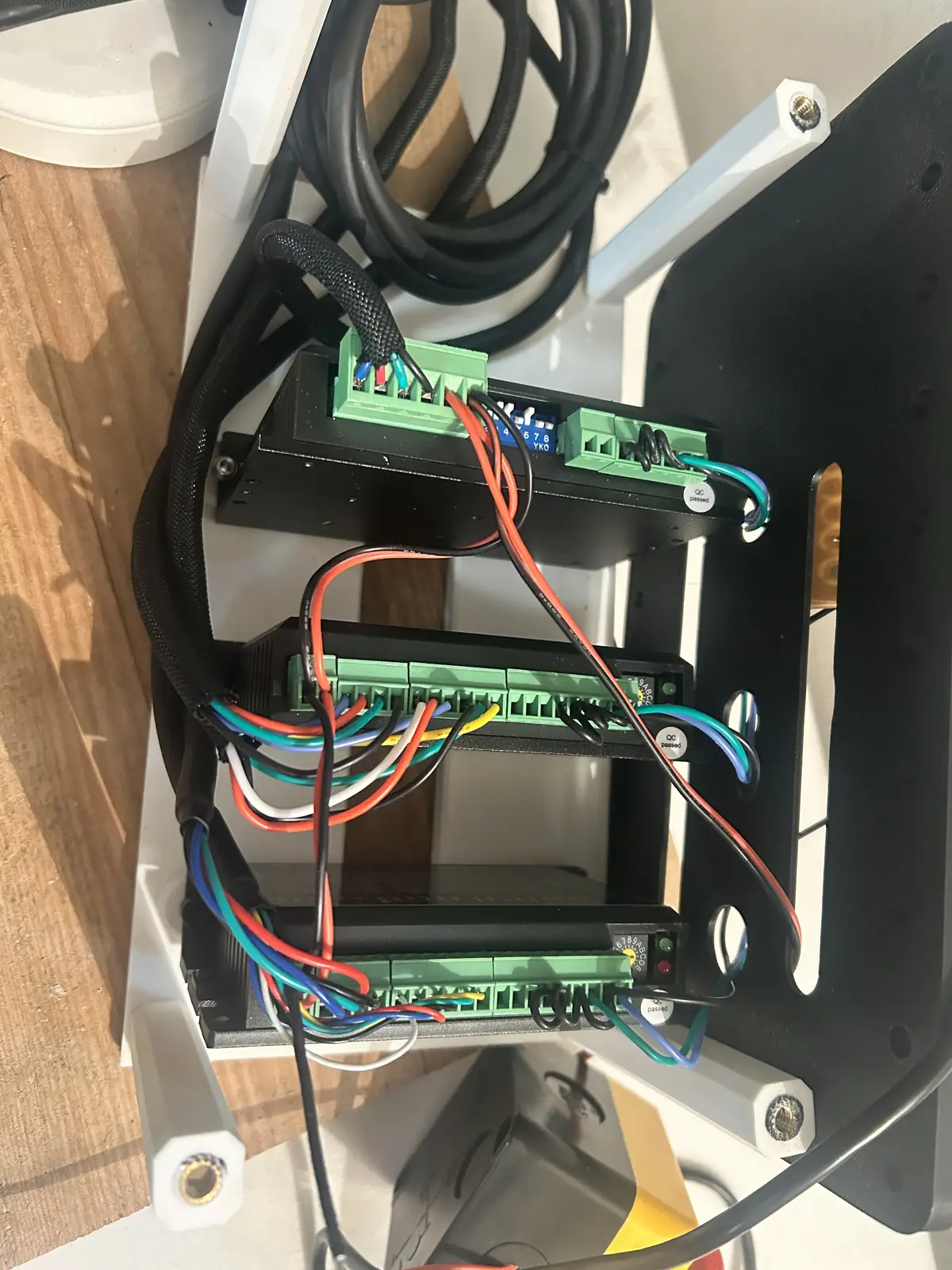
Each motor is routed down to the central driver enclosure using zipties and braided cable, which I installed over the bare wires using this cable sleeve tool, which was extremely helpful in fitting the sleeving over the wires. The four motors above the base are all tied together behind the shoulder joint, where they converge and then go down into a little area reserved for extra wiring, which then feeds into the enclosure.

I have, obviously, wired each driver to the corresponding motor's phase wires, or else they wouldnt rotate properly. And then I have a signal ground wire going from each of the negative terminals of the driver (DIR -, PUL -, and ENA -). Jumpers route this ground signal to each driver, so that there is only one connection to signal ground on the PCB. And, there are two wires running from each driver to dedicated solder pads on the PCB for DIR and STEP:
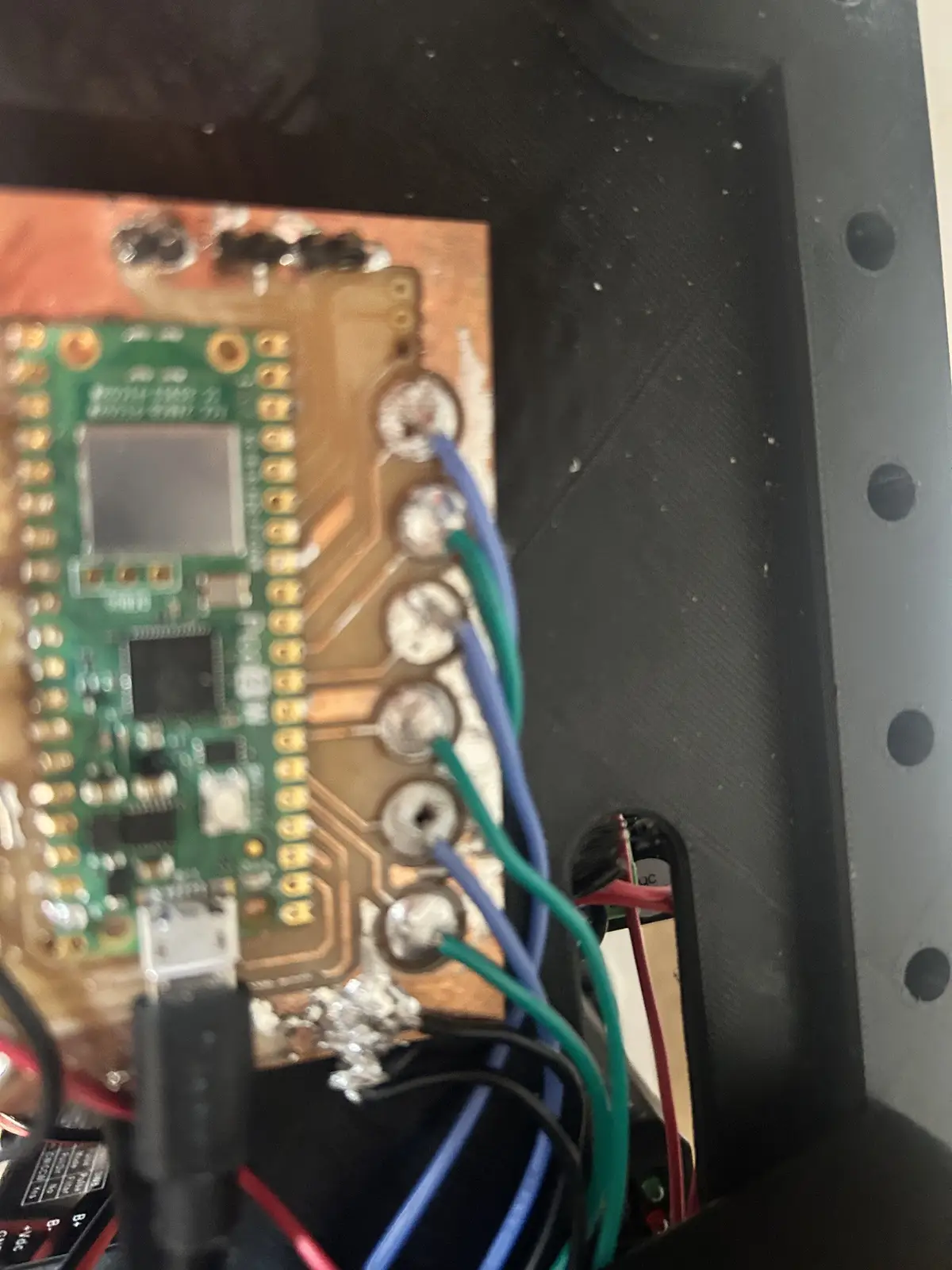
And on the drivers
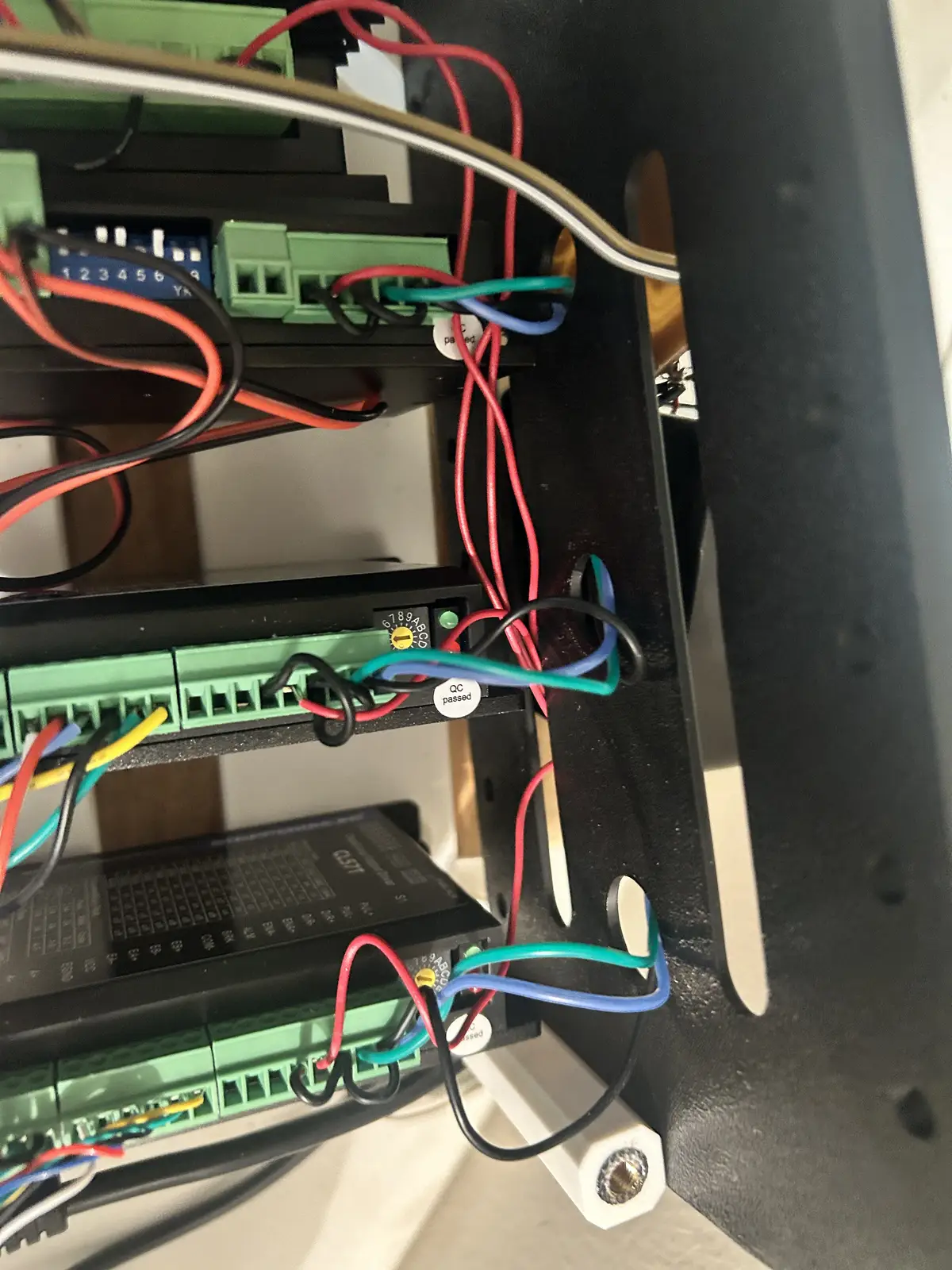
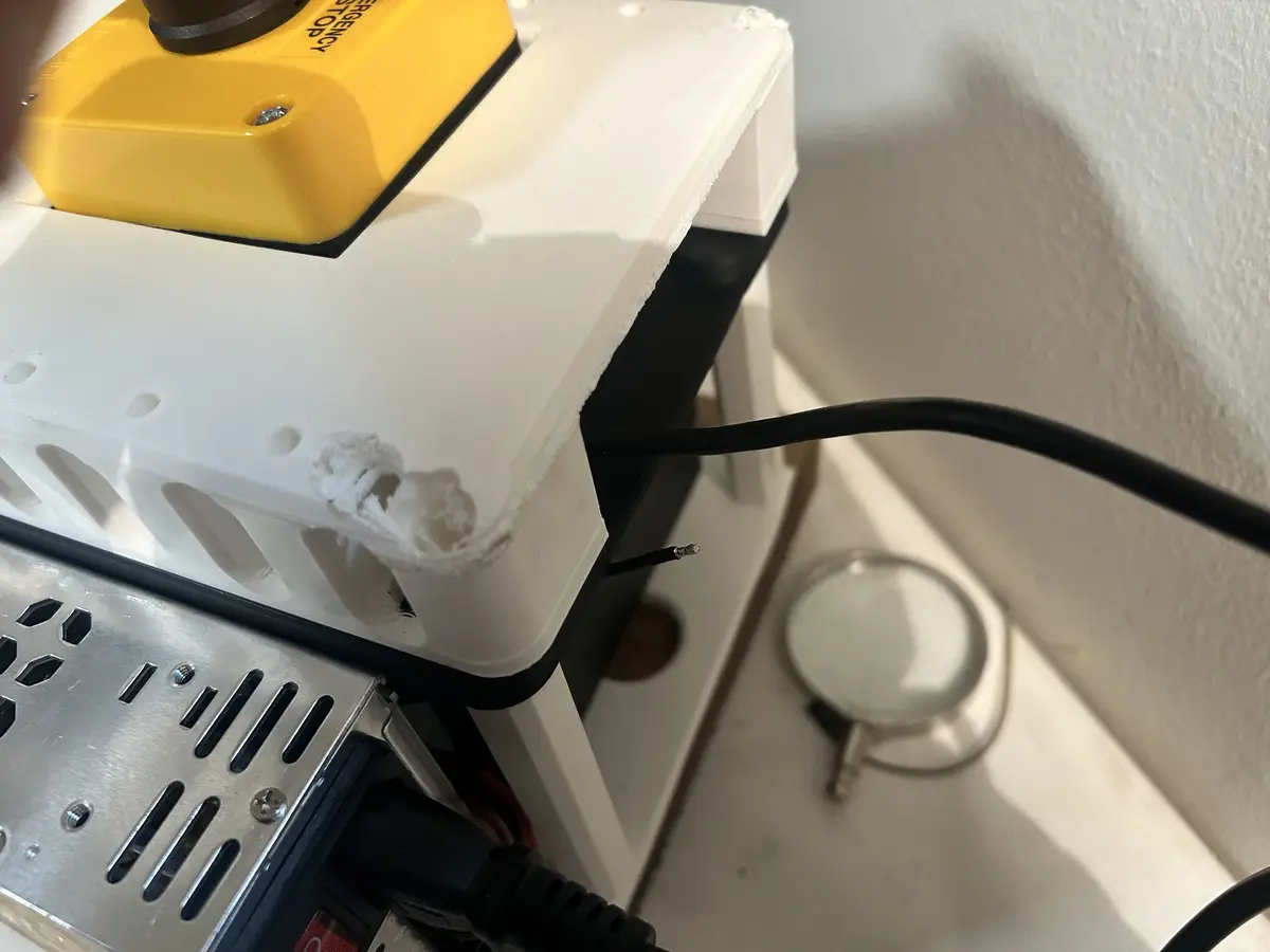
I have each step/dir pin different colors, and not each joint's pair of step/dir unique colors because I dont have enough unique wires, and also because as long as the individual driver's step/dir are adjacent, I can just change the pins in software. Additionally, I have an E-stop button in between the 5v bus on the Pico to each enable pin on the driver:
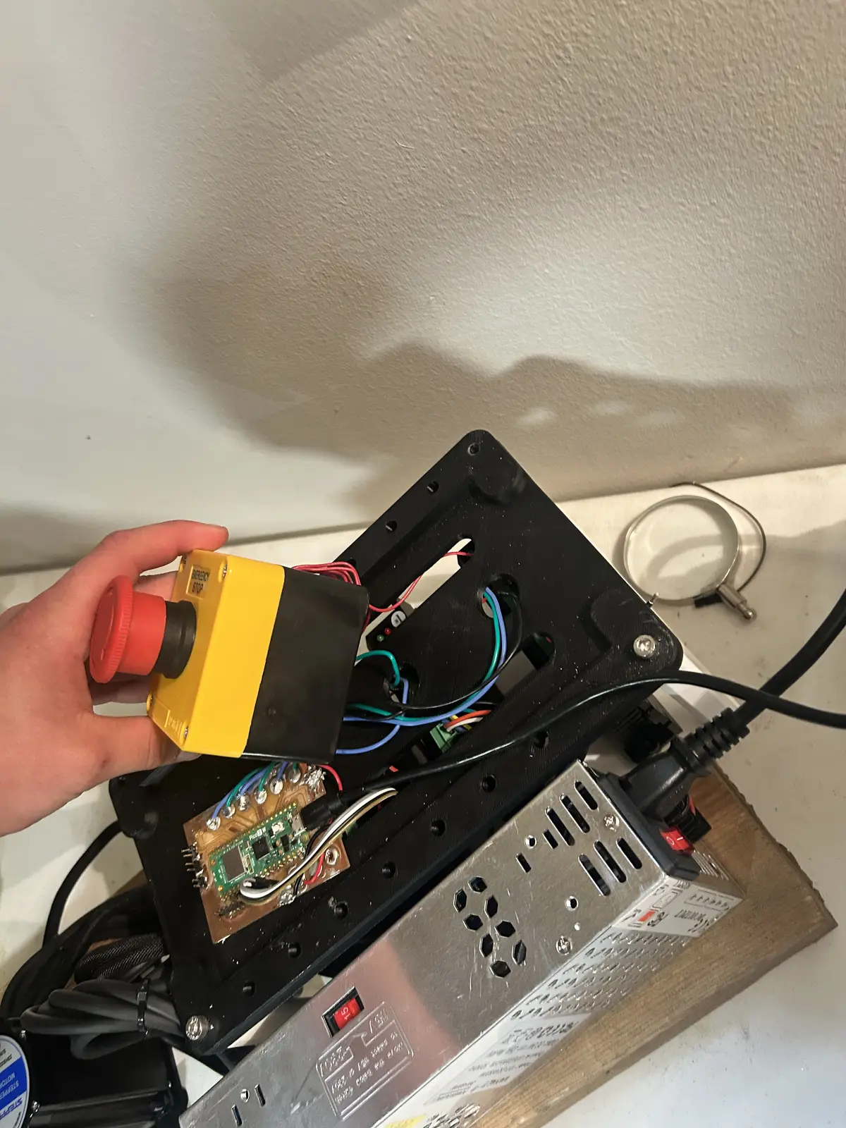
I unscrewed the estop button and split it into its two halves, connected wires to each enable pin on the drivers, twisted them together, then screwed them down to one side of the NO terminal on the estop. The other side of the NO terminal goes to the 5v bus on the pico, and is soldered down permanently.
So now, I can stop the motors in place without needing to cut power, which prevents the arm from crashing down and damaging itself or the surroundings.
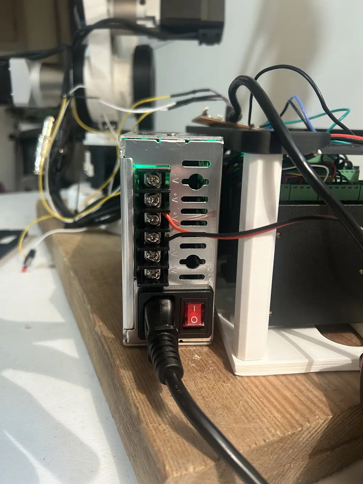
My power solution is a 24v 400W PSU from amazon. I was originally going to use a 36v PSU from stepperonline, but I was advised against that by my instructor, as 36v is dangerous, and the only way to provide wall power to the psu was by stripping a power cord and connecting the bare Hot, Neutral, and Ground wires, to the screw terminals. So, I bought one that had a plug. Each driver is connected to power in a chain, like this:
And then those two wires screw into the PSU's screw terminal:
And finally, for the microcontroller. It connects to the computer running LinuxCNC via USB (I talk more about the software below), with the USB cable plugging into the Pico 2W and running out of the top cover.
And runs to the computer
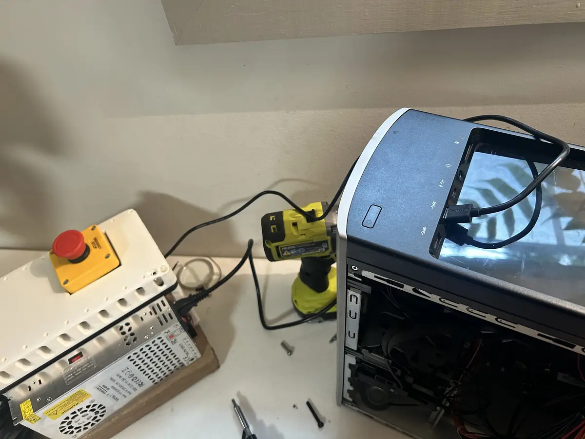
With this overall wiring solution, each motor has its complete necessary range of motion for regular operation, which is a huge win.
2D Manufactuing
CNC Routing
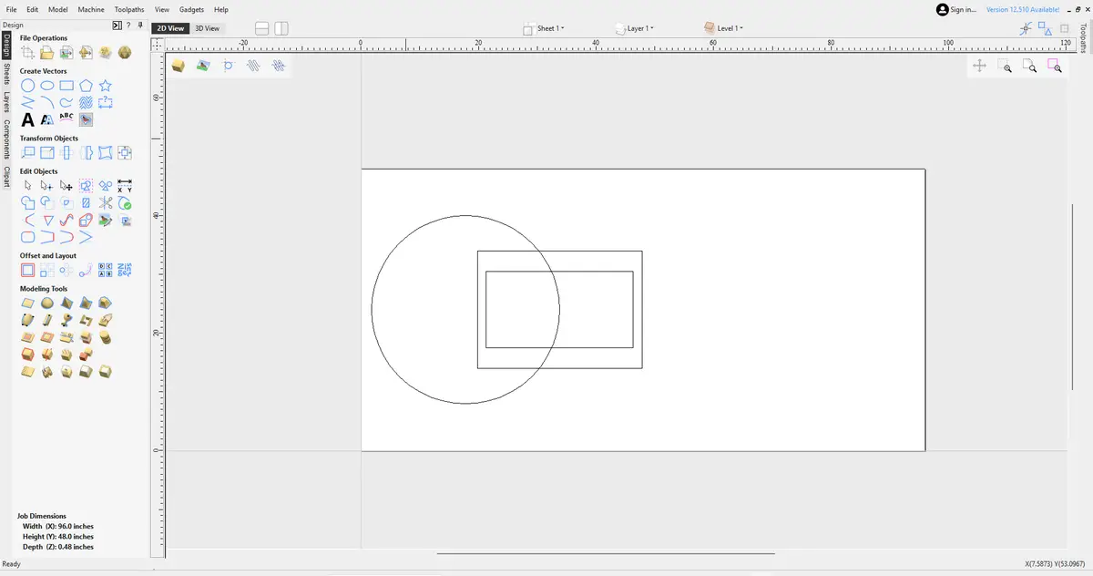
To meet the 2d process requirement for the project, I milled a large workspace panel out of a sheet of plywood on our lab's Shopbot. For more information, please refer to the Computer Controlled Machining Week. I used Aspire for design and toolpath creation. I used simple shapes (a cirlce and two rectangles) to create the basic shape.
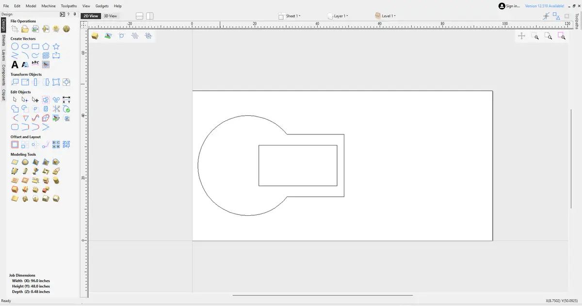
And the trim tool to get rid of the unnecessary vectors to create this shape:
I initially was going to add a two lines with increments at the center of the cirle like this:
and use an engraving toolpath, but I couldnt figure out how to design them inside of Aspire. bThen I opened the 'toolpaths' tab and created the profile toolpath first, using the 3/8 compression bit and selecting the outline to cut the piece out.
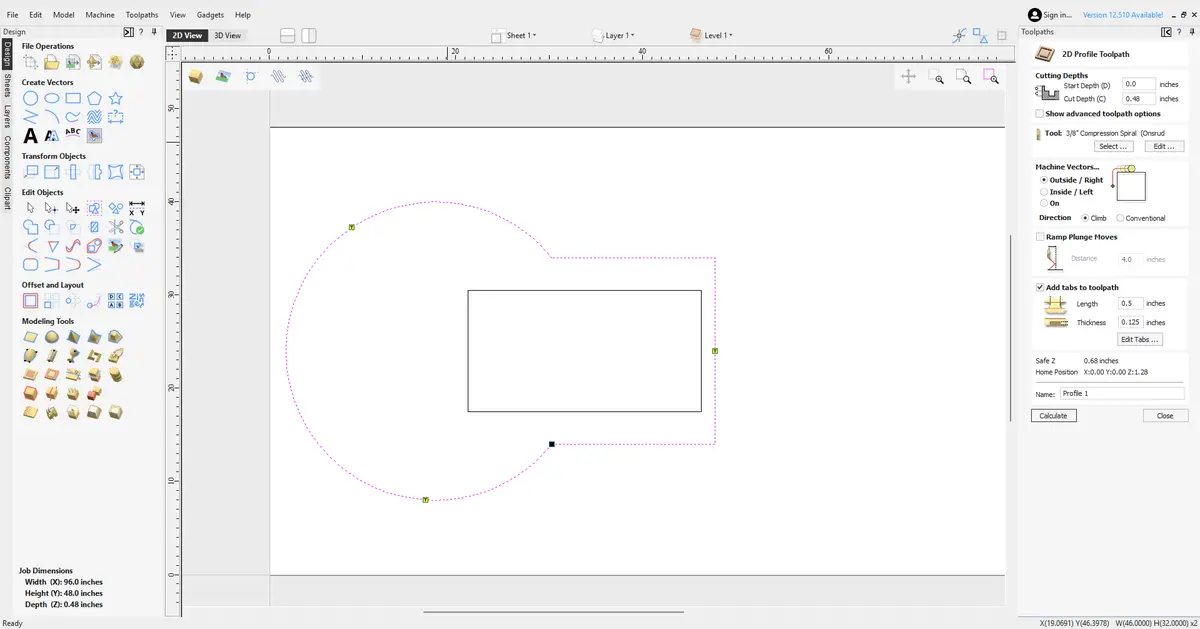
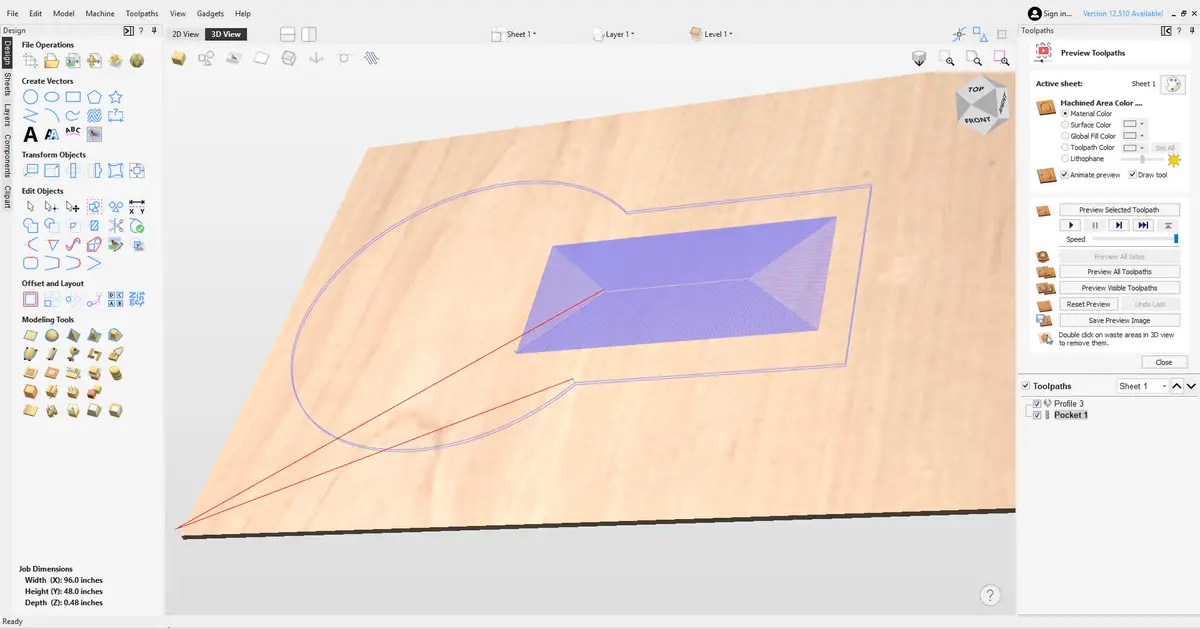
And then I created a pocket toolpath to create a little recession in the material, so the arm's wooden base will have somewhere to cleanly sit. I added 3 tabs to the toolpath, so the piece wouldnt fly off and damage itself when the run finishes.
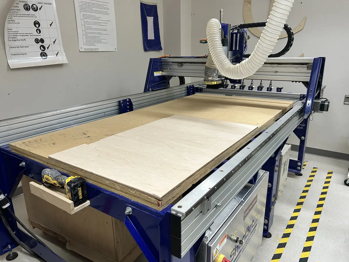
Then, I grabbed my material (half inch plywood) and fastened it to the bed using the process described in Week 7.
Then, with the aspire file open on the shopbot computer, I exported the pocket toolpath first as a .sbp file (once again according to the process described in week 7) and ran it. The file open in the software:
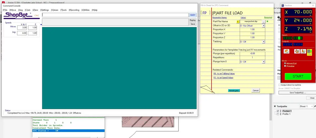
It automatically retrieved the tool from the rack in the back of the machine. Then, I repeated the same process for the profile toolpath to cut the shape out of the material:
And after milling:
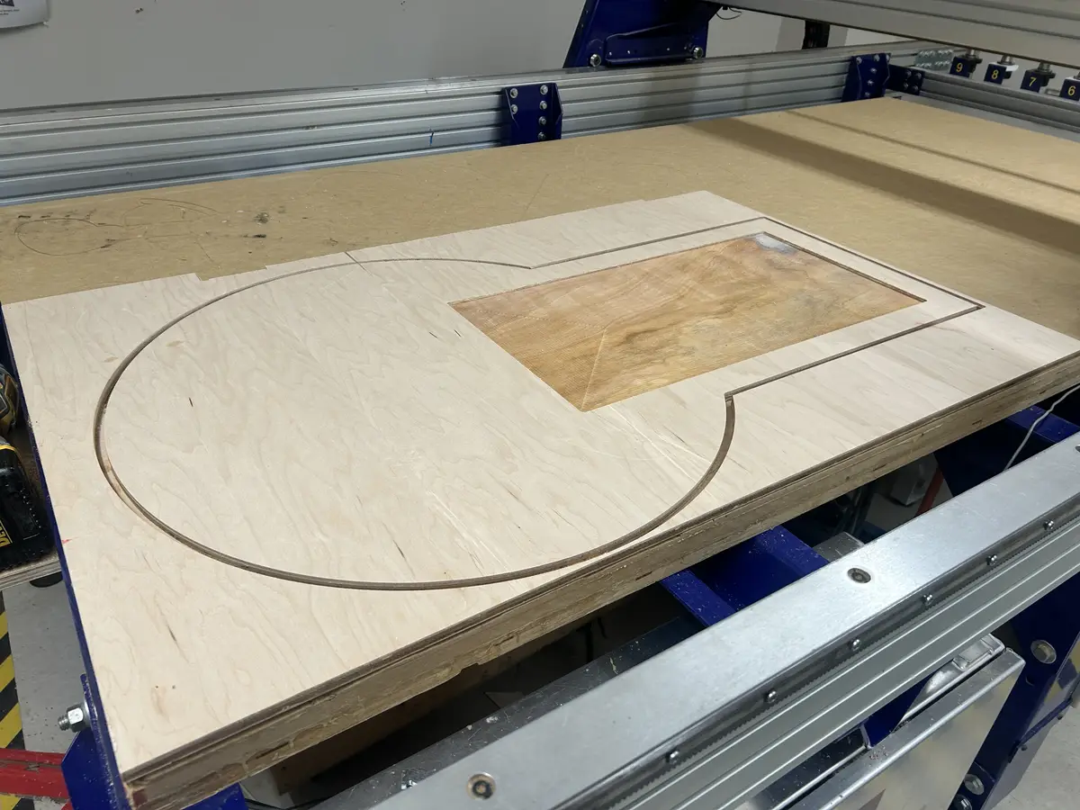
But, it didnt cut out great
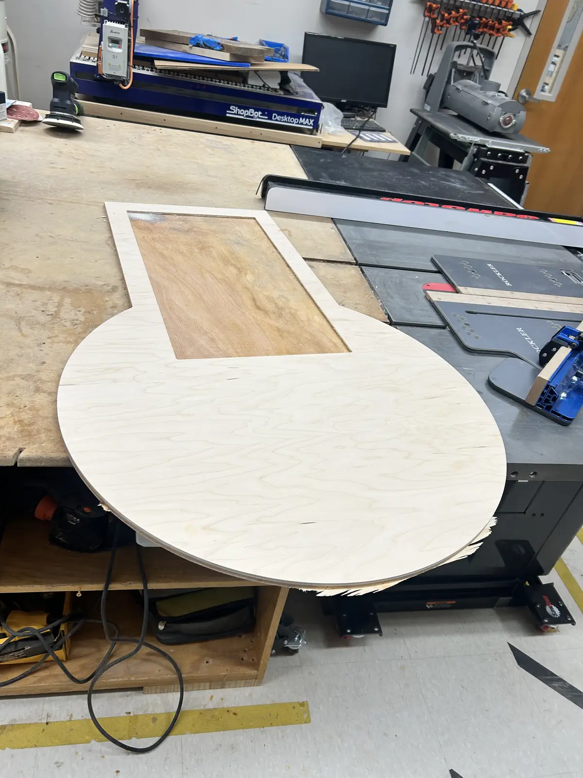
And this is what it looks like, after a quick sanding pass with 60 grit paper to smooth any rough edges.
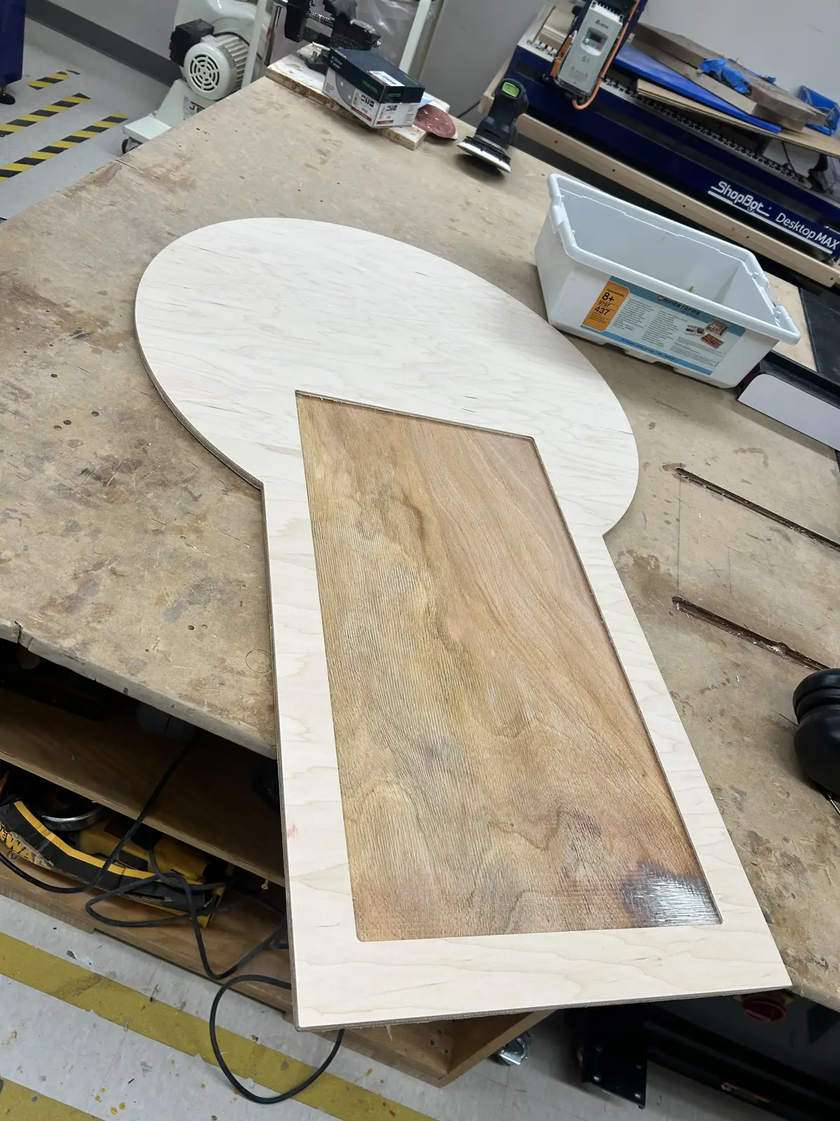
And in its final location, prepared and smoothed:
Vinyl Cutting
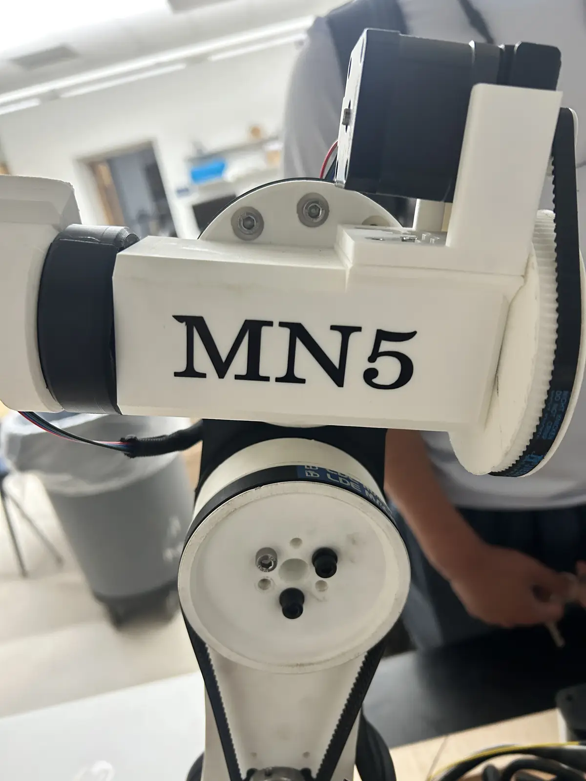
To make the otherwise ugly arm prettier, I decided to add a sticker onto a free area of the forearm:
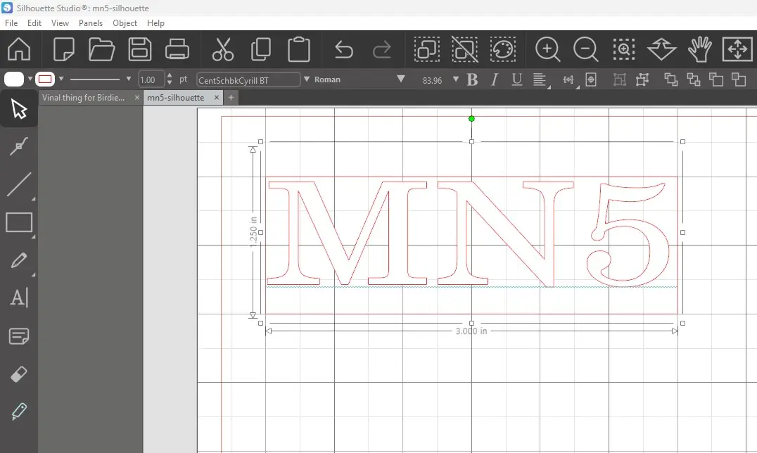
To preface this, I would like to say that I followed my workflow from Week 3 pretty closely, so please refer to it for more information on the process. First, I opened Silhouette Studio and dragged out a text box, typed "MN5" (My intials+ its a 5 axis robot), selected a cool font, scaled it to be roughly 90mm X 40mm, and added a box around it so the machine would cut the design out of the material.
Then, I went to the "Send" menu in the top right and prepared to send it over. I increased the force and blade depth, as these cutting mats and blades are not the greatest quality, so they require more force to actually cut through.
And I ran it:
And it came out great!
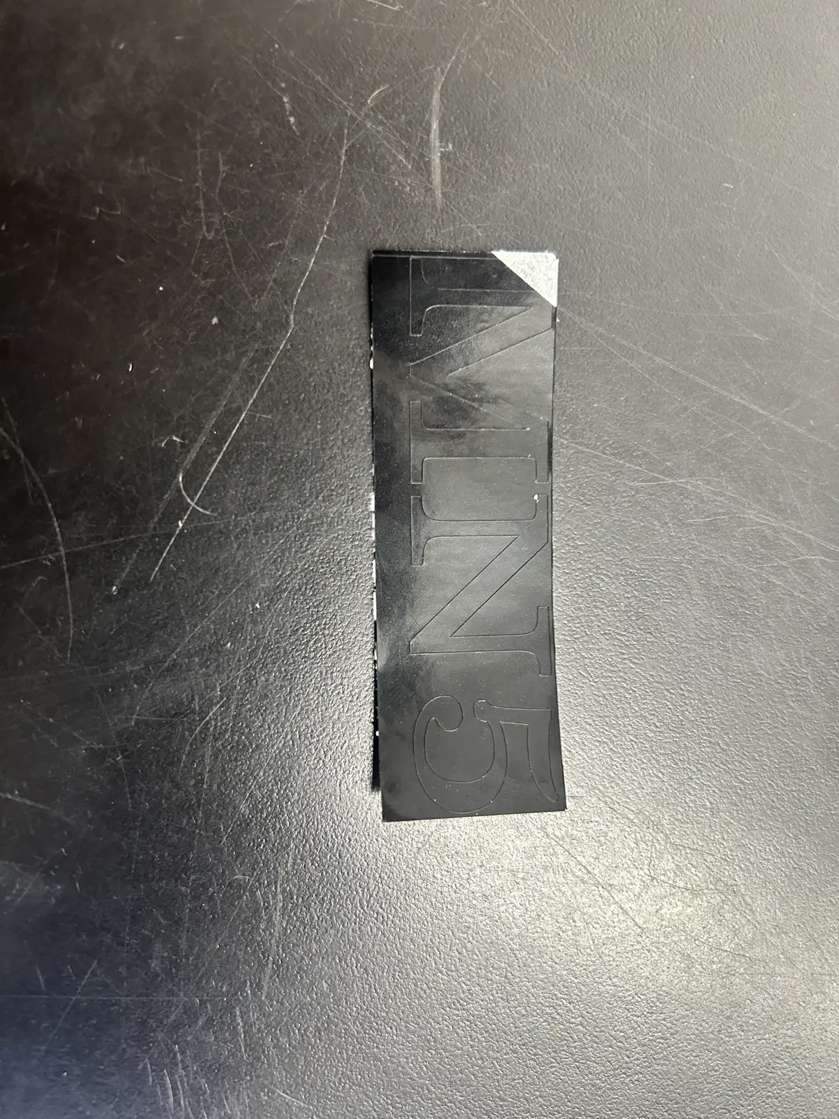
And I grabbed a pair of tweezers and removed the extraneous material:
And then moved it to the transfer tape. For more info on this, please refer to Week 3.
![]()
And then moved it to the final location:
![]()
And, extremely carefully as stickers do not adhere to 3d prints very well, I peeled off the transfer tape and left behind the finished sticker.
Software
This section contains the complete software setup for the project: the LinuxCNC install, the INI/HAL configuration, the genserkins DH parameter definition, the custom motion pipeline that talks to the Pico, and the VisMach visualization. This is by far the hardest part of the whole build, but also the most rewarding.
The Computer and OS
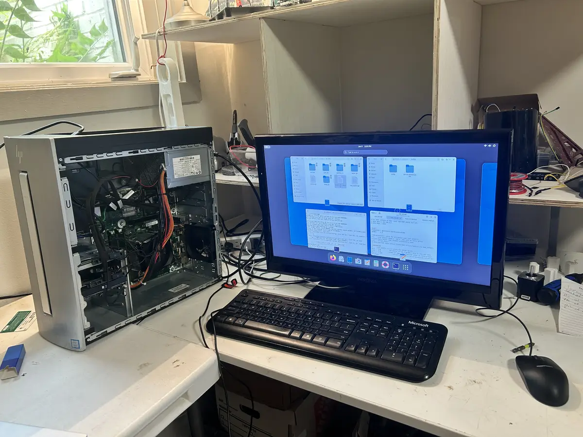
I started by picking up a cheap used computer (you don't need anything powerful for this). In my case, I found an HP Envy with an i5 7th gen CPU, 12gb ddr4 RAM, and a 1tb hdd + 128gb ssd for around $70. Then I downloaded the official Debian Trixie ISO, flashed it onto a USB drive with Rufus, and booted into it on the PC. I ran the installer, and once I was in, I gave myself root permissions to begin preparing the computer to run LinuxCNC. Its not a super powerful computer, but it doesnt need to be. If you were wondering, it will probably become a NAS or some other server after its usefullness here expires. Also, the USB keyboard and mouse I just found around the house, and the monitor is an old TV we had lying around.
LinuxCNC and the Real-Time Kernel
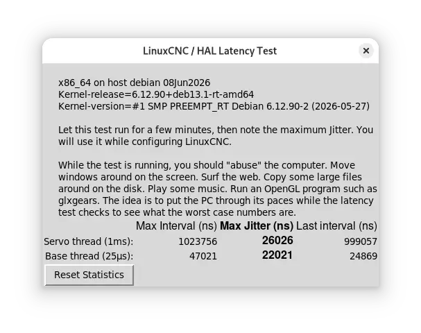
Next I installed the real-time kernel for LinuxCNC, then LinuxCNC itself. LinuxCNC needs a real-time kernel because it has to step the motors at a precise, predictable rate. To check how well the machine could keep that rate, I ran the latency test, and I got around 25000 ns max jitter. That is well within range for what I am doing.
When using an external motion controller, step and direction pulses are generated on the controller hardware rather than the host PC, so the kernel only needs to maintain reliable periodic communication and the tolerable latency is on the order of tens of microseconds rather than the sub-microsecond timing software stepping demands. The LinuxCNC latency test (latency-test) still provides a useful baseline by running a periodic real-time thread under deliberate system load and recording the maximum observed jitter, since excessive jitter can delay communication with the controller and trigger a following error or watchdog fault. PREEMPT_RT on Debian is well suited to this setup because it makes most of the kernel preemptible and bounds real-time thread latency, which is sufficient to service an external controller reliably without the aggressive BIOS and kernel tuning often required for software stepping. I was initially going to use a Raspberry Pi 4 for this purpose, but it could not complete the iterative inverse-kinematics solve within the servo period reliably. genserkins solves the arm's inverse kinematics numerically every servo cycle, and on the Pi 4 that work couldn't finish inside the real-time deadline, so the solver kept getting preempted and reporting failures. It wasn't that the math was too hard arithmetically — it was that the Pi couldn't guarantee it finished in time, every time. The desktop's faster cores and lower real-time latency close that gap (for proof: I used the exact same config on the RPi4 and the desktop computer, and it only worked on the desktop).
After that, I used Claude to help generate the INI and HAL files, which are the two configuration files that actually define and run the machine. Also, the way you run linuxcnc with the robot arm config is by CD'ing into the config folder in a terminal and running
And this is what the desktop GUI looks like, on the 'joint jog' menu:
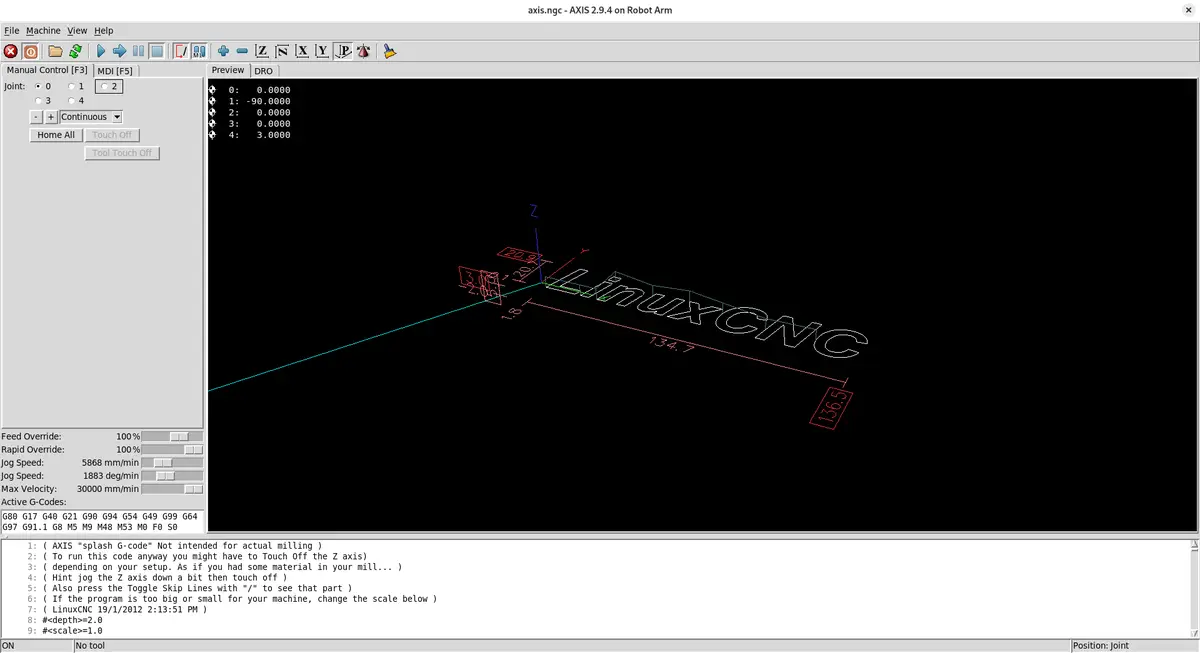
After moving each joint into its homed position, which I did like this:
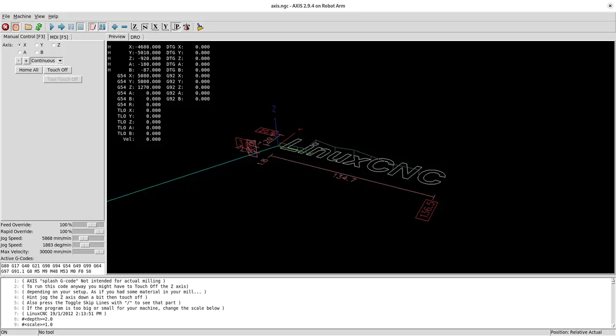
You can then switch to 'World Jog' mode by pressing $ (or more accurately shift + 4), which allows you to perform world jogs, and move the End Effector in 3d space along all 5 of its axes:
The INI File
The INI file is used to initialize the machine. It defines stuff like the axis setup and the unit setup (I use millimeters), and it initializes the kinematics module. For my arm I used genserkins, LinuxCNC's general serial kinematics module. Robot arms in are called “serial” because their joints and links are connected one after another in a chain, just like links in a serial sequence. This means the motion of each joint affects all joints that come after it, giving the arm a wide range of movement but also making control more complex.
For each joint you define max velocity, max acceleration, and the software limits (the maximum range of travel for that joint). You also have to define each world axis coordinate individually if you want to perform a world jog. If you don't do this, you will not be able to world jog, it will just crawl at an incredibly slow speed. I found that out the hard way. You can find it in the config folder below, among the other config files. LinuxCNC Config
A joint jog moves one motor directly: you pick a joint, press a key, and that single joint rotates. A world jog moves the end-effector through 3D space — you tell it "go +X" and LinuxCNC runs inverse kinematics every servo cycle to figure out which combination of all five joint angles produces that straight-line motion of the tool tip. This is why the per-axis world coordinate definitions matter: without them, LinuxCNC has no velocity limits to plan Cartesian moves against, and the motion crawls.
You must also include a .TBL file that contains your "tool" data, even if you do not have one. It must be defined in the INI, and you can find more information on how it works in the INI setup document linked above. As I do not work with it much in my project, I will not be discussing in depth.
; Tool table for robot arm
; T1: EE with 2.5-unit wrist link offset along EE x-axis
T1 P1 X0 Y0 Z2.5 A0 B0 C0 U0 V0 W0 D0 I0 J0 Q0 ;
Additionaly, you must include a .VAR file, LinuxCNC's persistent store for numbered G-code parameters, most importantly the G54–G59 work coordinate offsets, so that the position you touch off and the coordinate system you select survive between sessions instead of resetting every startup. It lives alongside your INI and HAL files (referenced by PARAMETER_FILE in the [RS274NGC] section), sits at the G-code interpreter layer well above kinematics and the Pico, and is managed automatically by LinuxCNC so you normally never edit it by hand. All you must do is define it in the gcode interpreter section of the INI file (and create the .var file), and LinuxCNC will fill it in for you.
Homing
Inside each joint's configuration you also have to define the homing sequence. I don't use limit switches on any joint, so I set the homing velocity and homing search speeds to zero for every joint. That tells the machine not to run a search routine when I press the Home button — instead it just adopts its current position as the home position.
So I home the machine by hand: with the machine powered off, I physically move each axis to its zero position, power it back on, then press Home. Not very precise, but that is how I got it working.
The other essential thing defined in each joint's setup is the maximum following error. LinuxCNC is built for high-precision applications and it expects position feedback from the controller. The Pico generates the steps and reports its position back to the computer, and LinuxCNC compares that against where it commanded the joint to be. If the difference exceeds the maximum following error, it faults out. More on that in the problems section.
Kinematics and the DH Parameters
For the kinematics I used the genserkins module that ships with LinuxCNC. It is short for general serial kinematics. It defaults to 6-axis robot arms, but it works fine on a 5-axis arm like mine, I just don't need the tool-rotation axis.
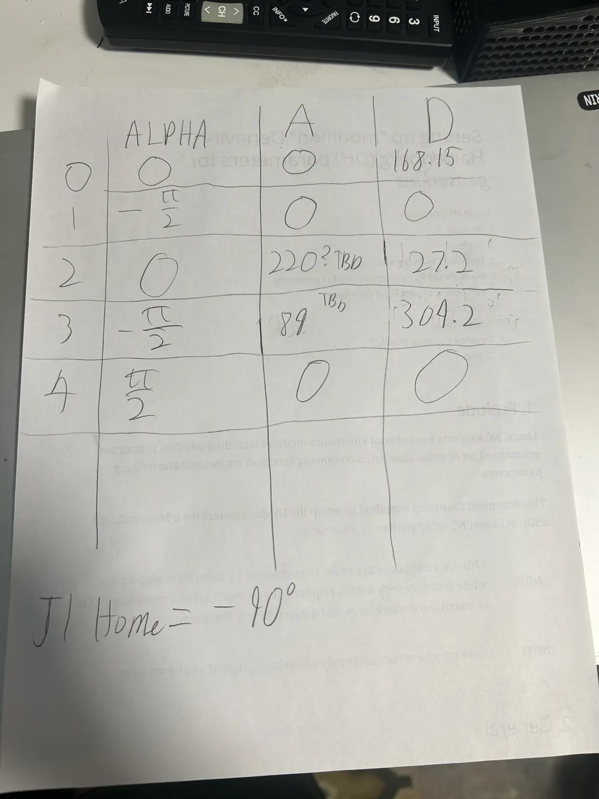
To set it up, I sat down with the printed-out LinuxCNC DH parameters document, which walks you through translating your robot into a set of values called the Denavit–Hartenberg parameters (shortened to DH). I cross-checked everything against my CAD model and filled in the parameters. Those are the values genserkins uses as a reference to calculate the joint angles. The DH convention is universal — every serial robot arm can be described by it — but the actual values are unique to each arm, derived from its specific link lengths and joint geometry.
Each joint is described by four standard numbers: a (link length, how far apart two consecutive joint axes are), α (link twist, the angle between those axes), d (link offset, how far along the axis the next link sits), and θ (the joint angle). For a rotary joint like every joint on my arm, θ is the variable the motor changes, while a, α, and d are fixed by the physical build.
LinuxCNC's genserkins reads these as named values in the [GENSERKINS] section of the INI — A_0, ALPHA_0, D_0, A_1, ALPHA_1, and so on, one set per joint. From them it builds the chain of transforms that defines forward kinematics (joint angles → tool position). The clever part is the reverse: every servo cycle, when I world-jog, genserkins takes the desired tool position and solves that transform chain backwards numerically to find the joint angles that achieve it. That numerical inverse solve, repeated at the servo rate, is exactly the workload the Raspberry Pi 4 couldn't keep up with. It also means a single wrong or missing DH value (I lost an afternoon to one undefined ALPHA term) makes the solver describe an arm that doesn't match reality, and inverse kinematics fails or produces impossible joint angles. Below is the chart I created with my arm's CAD model and the LinuxCNC DH parameter document.
The HAL File
The HAL (Hardware Abstraction Layer) in LinuxCNC is a modular framework that connects software components—like motion control, encoders, and I/O—through configurable signals, pins, and parameters, much like wiring together physical electronic components. It lets you map real or simulated hardware to LinuxCNC's internal logic without changing source code, so you can route signals between drivers, motion controllers, and GUI elements purely through configuration files. In layman's terms, the HAL file is what links everything together. It connects the kinematics joint positions to the motion controller's joint positions. You can find the HAL file in the .zip folder below, among the other required machine files. LinuxCNC Config Download
From the HAL file, the motion connects to a custom Python script running on the computer (also generated by Claude). That script communicates with a Raspberry Pi Pico 2W running custom MicroPython firmware. The firmware holds, for each axis: the step and dir pins, the steps per revolution, and whether the axis should be inverted to match the DH model. It is in MicroPython instead of C because I do not understand C at all, while I have a small enough understanding of MicroPython to make little changes myself.
Here is the whole signal chain, from the motion planner down to the motors:
┌─────────────────────────────────────────────────────────────┐
│  Desktop PC (Debian + PREEMPT_RT)                            │
│                                                              │
│   LinuxCNC  ──►  genserkins  ──►  HAL  ──►  pico_hal.py      │
│   (planner)     (kinematics)    (wiring)   (Python bridge)   │
└───────────────────────────────────────────────┬─────────────┘
                                                 │  USB serial
                                                 │  (binary protocol:
                                                 │   5 joint angles + feedback)
                                                 ▼
┌─────────────────────────────────────────────────────────────┐
│  Raspberry Pi Pico 2W (MicroPython firmware)                │
│                                                              │
│   parse packet ──► per-joint PIO state machines ──► STEP/DIR │
└───────────────────────────────────────────────┬─────────────┘
                                                 │  STEP / DIR pins
                                                 ▼
                              Stepper drivers  ──►  Stepper motors
                                                    (the arm joints)
The same joint-pos-commanded value that HAL feeds to pico_hal.py is also tapped off to the VisMach 3D model, so the on-screen arm and the physical arm always show the same commanded pose.
The Motion Pipeline
The script on the computer talks to the firmware on the Pico over a custom binary protocol that carries the absolute commanded joint angles (one float per joint, in degrees). The Pico does the math: it converts each commanded angle into an absolute step target using that joint's steps-per-revolution, then generates the steps needed to reach it. It reports its current position back in the same format so LinuxCNC can close its position loop.
I used a fixed-size binary packet rather than plain text for three reasons: it's compact (a handful of bytes per joint instead of a string of digits), it parses in constant time on the Pico with no slow string-to-float conversion, and the fixed length makes a dropped or misaligned packet trivial to detect — if the bytes don't line up to the expected size with the right start and end markers, the firmware throws the packet away and resyncs on the next one.
To actually generate the step signals, it uses the Pico's built-in PIO (Programmable Input/Output) state machines — one per joint. They run independently of the main processor, so step timing is never disturbed by interrupts or whatever the CPU is doing. Each state machine runs at a fixed clock, but the rate of each burst is set on the fly: every servo cycle the firmware works out the exact velocity LinuxCNC commanded for that joint and feeds the PIO a matching per-step delay. That means the motor turns at precisely the commanded speed in smooth, continuous motion, rather than firing each move as a full-speed burst followed by an idle gap (which is what causes steppers to buzz and vibrate).
A PIO state machine is a tiny dedicated processor inside the Pico that runs its own minimal program separate from the main CPU — just enough instructions to toggle pins with cycle-exact timing. Because it isn't running Python and can't be interrupted by anything else on the chip, the pulses it produces are perfectly evenly spaced. If the main CPU generated the pulses instead, every garbage-collection pause or incoming serial packet would jitter the timing and the motor would stutter.
It communicates over the Pico's regular USB port. That works, but it isn't ideal, and at the time I didn't realize there were better options, there exist Pico 2W variants with built-in Ethernet ports that would enable much higher-speed communication.
The HAL file also a genuinely amazing number of variables, way more than I use. There is per-joint homing status (whether a joint is actively homing, homed, or not), spindle controls (which obviously don't apply to me, I am not putting a large spinning piece of sharp tooling on the end of a fragile printed arm), and a lot more. It is an extremely powerful tool.
VisMach Visualization
The HAL file also initializes a VisMach Python script (Claude generated the first version on its initial run as a little starting summary). VisMach is a software visualization of where the arm is in space.
To build it, I went into Fusion 360 (where I modeled the arm) and exported the ASCII STLs, not the binary STLs. That part is important: binary STLs will not work. Then I took the initial Claude-generated script, imported all the STLs, added them to their respective joint definitions, and added primitives for the base (rather than importing a static model, which I don't know how to do). I applied the correct transformations to each model and linked them with the proper ratio to the HAL file's joint-pos-commanded variable, which is the same variable the Pico motion controller reads from. So the on-screen model and the real arm both follow the same commanded position. This is what the GUI looks like, at an arbitrary position.
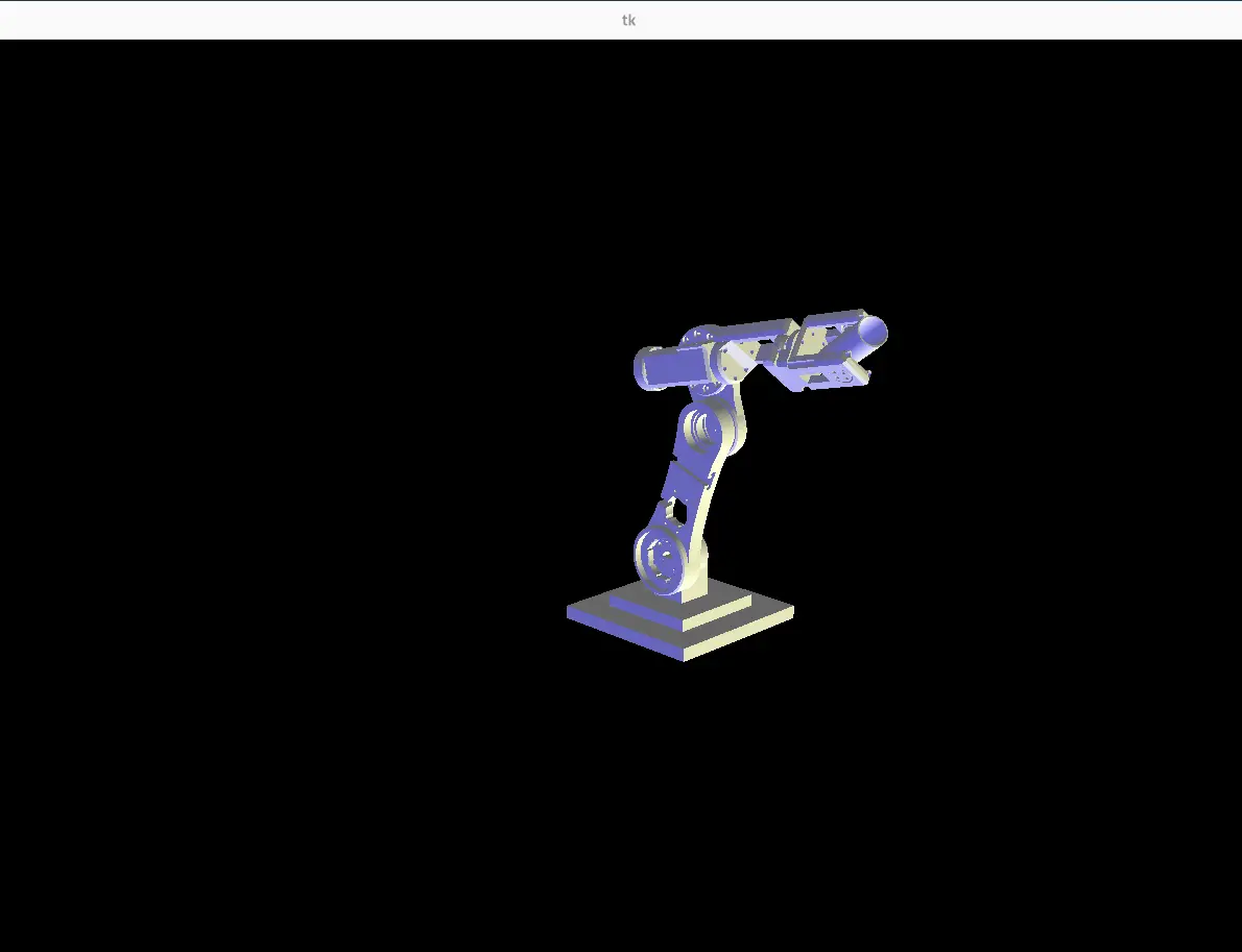
The reason watching the commanded position matters so much comes down to one fact about this arm: there are no encoders. LinuxCNC only ever knows where it told the joints to go, not where they physically are — the Pico reports back the steps it generated, which is the same commanded number, not a real measurement. VisMach shows you that commanded world: the on-screen arm is a perfect render of where the controller believes the arm is.
That makes the on-screen model and the physical arm a built-in comparison. If a motor stalls, skips steps, or a belt slips, the controller never finds out — but the real arm visibly drifts away from the VisMach model. So the visualization isn't just a pretty display; with no encoder feedback, it's the only way to see the gap between the commanded pose and reality and catch when the open-loop assumption has broken down. It also lets me dry-run and verify a move on screen before committing the physical arm to it.
Problems I Hit
The protocol didn't match. The AI-generated code wasn't communicating over USB correctly, there was a small mismatch in the binary protocol between the HAL-side script and the Pico firmware. Lining the two up fixed it.
The two sides disagreed on the packet length. At one point the computer-side script was sending a 23-byte packet (it had an extra byte tacked on the end) while the firmware was still expecting 22 bytes. Because the lengths didn't match, every packet after the first was read starting one byte off, so the float data decoded into garbage. I tracked it down by dumping the raw bytes the Pico was actually receiving and seeing the start marker land in the wrong position. Once both sides agreed on the exact byte layout, it lined up immediately.
chmod +x. I don't use Linux, so I spent about an hour banging my head on the keyboard before realizing you have to run chmod +x on the HAL script to make it executable. Without that you just keep hitting the same "not executable" error over and over.
Line endings. When you bring files from Windows into Linux, the line endings are different. Windows uses CRLF and Linux expects LF, and the parser will choke on the Windows endings and refuse to read the file. You have to convert CRLF to LF first.
The fix is to strip the carriage returns. I ran sed -i 's/\r$//' filename on each file after copying it over (the dos2unix filename utility does the same thing if you have it installed).
Following errors and position feedback. As mentioned above, LinuxCNC requires position feedback or you get a joint following error. The Pico generates the steps and sends back its position, and LinuxCNC checks whether that exceeds the maximum following error defined in the joint setup. If it does, it doesn't cut power, but it blocks itself from setting any new joint positions. Importantly, there are no actual encoders, the Pico just reports the steps it generated and derives the joint position from that. I went this route for two reasons: the Pico does not have enough IO to support real encoders on every joint, and adding them would be an entire extra layer that is way overkill for what I am trying to do.
Running Gcode was another huge problem I had. Whenever I would run a gcode file, I would always experience an issue with joints reaching their soft limits, so my solution? Set the software limits to +- 200000 degrees, and the problem was solved! I used chatGPT to generate gcode for the arm, and I told it that I wanted gcode for a 5 axis robot arm running genserkins, and I wanted it to trace ____ pattern, which I repeated multiple times to get different patterns. Below you can find clips of the arm working, as well as download the .NGC gcode files. Opening gcode on linuxcnc is really simple, just click on the folder button to the right of the estop/machine power button which takes you to the file selection, then just select your gcode. To run it, just press the "play" button on the same menu level. In order to change your work offset (ie, where 0,0,0 is for your gcode), run 'G10 L20 P1 X0 Y0 Z0' in the MDI terminal, substituting the XYZ zeroes for your desired offset value.
For the first file, I asked chat gpt to generate me a gcode file that starts from 0,0,0 and traces a circle on each face of a cube.
For the second file, I told chatGPT to generate me a gcode file that traces 5 circles parallel to the xy plane in random positions within +-200, +-200, +-200 of 0,0,0.
Results
Below are clips of the arm working properly. It was really good at World Jogging which means issuing real‑time Cartesian jog commands that the kinematics module continuously resolves into coordinated joint‑space motion while respecting axis limits, homing states, and servo‑thread timing. Because LinuxCNC’s motion planner interpolates these jog vectors at the servo period, the arm can maintain smooth multi‑axis trajectories even during rapid operator‑driven adjustments in X/Y/Z and tool‑orientation axes.
Downloads
Individual Parts Folder This folder contains every 3d file for the entire project, including the mount for the drivers.