Week 15
Check List
This week's project requirements:-
- Document your work on the group work page
- Reflect on what you learned on your individual page
Individual Assignment:
-
- Explain the UI that you made and how you did it.
- Explain how your application communicates with your embedded microcontroller board.
- Explain any problems you encountered and how you fixed them.
Images/Files:
- Include your original source code or a screenshot of the app code if thats not possible.
- Properly compress or use a zip folder if needed
- Include hero shots of your results
Group Assignment:
Resources and Helpful Links
Learning Outcomes
- Implement a User Interface (UI) using programming and explore protocols to communicate with a microcontroller board that you designed and made.
Group Work
My Contribution to the Group Work
This week we were tasked with an individual set of activities and group work. Working as a group, we needed to copmpare as many tool options as possible. For our individual activities this week, we were tasked with writing an application that interfaces an input and/or output using an embedded board that we made.
My group worked on trying a variety of different user interface design tools and methods such as Processing, Arduino IDE Serial Potter, React, and Touch Designer. Each memeber in our group focused on trying out one or two of the tools and methods, and then we shared our results with each other. For my portion of the group work, I focused on trying out and documenting TouchDesigner.
-
My Contributions to this week:
- Documenting TouchDesigner, what it is, its hardware needs, use cases, pros and cons, and its monetary needs.
- Showing my group members how to use TouchDesigner by showing them a project built in TouchDesigner.
- Sharing with my group how to find helpful resources for TouchDesigner.
For a more in depth look at my groups week 15 assignment, see my groups Week 15 page.
Introduction
For this week I tried out a variety of different methods of user interface design. For this weeks project I focused on returning to my TouchDesigner project I attempted in week 11. During this week I also tried out Processing IDE which I used to visualize my robots emotion system. This can be seen on my final project page.
My project for this week uses the custom ESP32-C6 breakout board I designed and fabricated in week 9. Connected to my board is the flex sensor input device which I documented in week 9 and week 10. The flexing of the sensor is detected by the ESP32-C6 on my breakout board, sent from Arduino IDE into TouchDesigner, and creates a live interactive visual effect on a digital sphere.
Setting Up Touch Designer
I started by opening a blank TouchDesigner project and followed a instagram tutorial I found online for setting up a basic project that reacts to serial data from an ultraSonic Sensor.
- Start by adding a SOP Sphere.
- Connect a SOP Noise to the Sphere.
- Connect a SOP Atribute Create to the Noise.
- Connect a SOP Null to the Attribute Create.
- Connect a COMP Geometry to the Null.
- Connect a MAT Phong as a material to the Geometry.
- Change the color of the Phong to your liking.
- Connect a TOP Render to the Geometry.
- Connect a COMP Camera and a COMP Light to the Render.
- Connect a SOP Null to the Render.
- Connect a SOP Out to the Null.
Steps for Setting up the Project
Creating the Interactive Sphere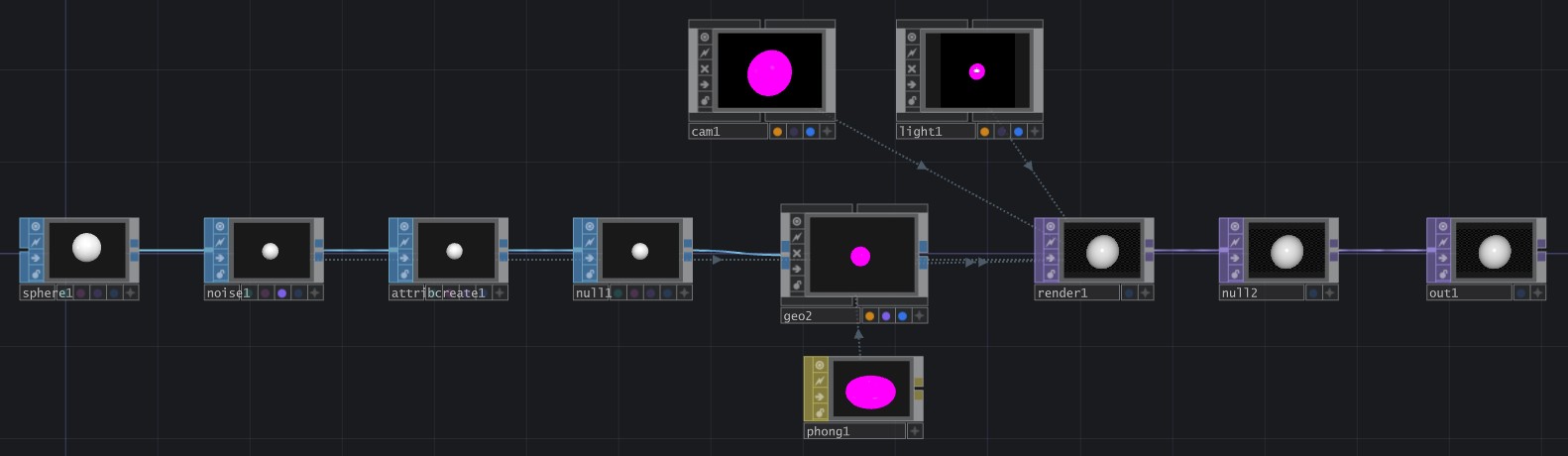
-
Setting Up the Serial Read Data
- Make sure Ardunio IDE is closed!
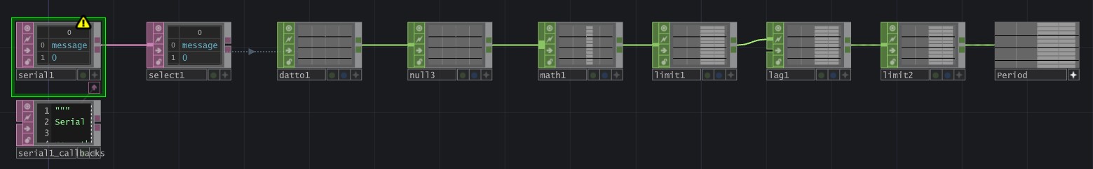
- Start by adding a DAT Serial.
- Match the Port and Baud Rate to your connected board.
- Connect a DAT Text to the Serial.
- Connect a DAT Select to the Serial.
- Change the Select Rows to by Index.
- Connect a CHOP DAT to, to the Select.
- Connect a CHOP Null to the DAT to.
- Connect a CHOP Math to the Null
- Change the From Range to match your flex sensor low and high values, and the To Range to 0 to 10.
- Connect a CHOP Limit to the Math.
- Change the type to Clamp with a minimum of 0 and a maximum of 10.
- Connect a CHOP Lag to the Limit.
- Change the Lag to 0.1 and the Overshoot to 0.5.
- Connect a CHOP Limit to the Lag.
- Connect a CHOP Null to the Limit.
- Connect the final Null back to the Amplitude of the Noise SOP in the sphere.
With the final Null connected back to the Noise SOP, the sphere will begin to lightly react to general noise in the system.
Conecting my Board
My ESP32-C6 breakout board with the flex sensor is connected to my computer through USB and the flex sensor is programmed through Arduino IDE. I used my basic flex code from weeks 9 and 10 to read the bending values from the flex sensor. I confiurmed that I could see the values change with the bending of the sensor in the Serial Monitor in Arduino IDE. Once I confirmed this, I closed Arduino IDE and opened TouchDesigner.
I double checked that the Port and Baud Rate in the Serial DAT node matched the Port and Baud Rate I was using in Arduino IDE. I then watched to see if the nodes in the Serial chain reacted to the flex sensor being bent.
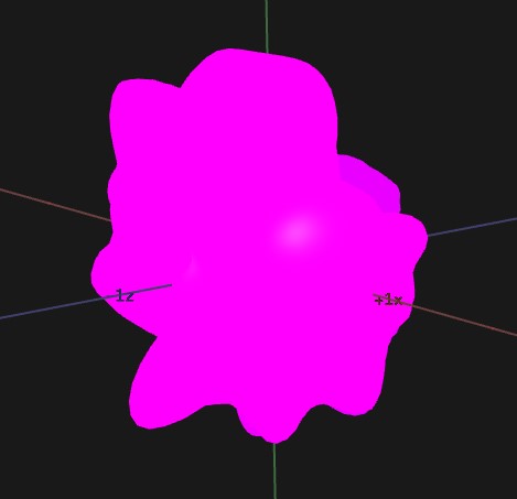
With everytihng confirmed, I opened the Camera view of my sphere and I began to flex the sensor. Bending the flex sensor on my board sent the data through the serial connection into TouchDesigner and caused my sphere to change in shape in real time. It was hard to see at first, due to the general noise in the system, but I tweaked the math and the lag node values and was able to get a better visual output on the sphere!
For the best live viewing results, change the Noise Type ot Brownian. This type is not as affected by the general noise and will grow and shrink with the flex sensor values more clearly.
Putting It All Together
-
System Workflow
- The flex sensor connected to my board acts as the input device for this project.
- When the sensor bends, the ESP32 reads the analog (bending) values and sends the data through the serial connection in Arduino IDE.
- TouchDesigner then reads the incoming serial data using a Serial DAT node.
- The incoming values are converted into usable values through CHOP nodes that are connected to a noise modifier node that changes the shape of my sphere.
- As the flex sensor bends the sphere deforms in real time.
This process creates a live interactive visual interface between my physical hardware and my digital sphere in TouchDesigner. I found this project to be a fun way to interact with my hardware. It was also useful for my final project, because it helped me explore how physical sensor inputs could be used to control my robots emotion system in real time. I think that the workflow of sending sensor data into an interactive software, like TouchDesigner, could later be expanded into controlling my robot’s expressions, animations, or emotional states.
Week 15 Files
In my repo is a zip folder containing files for my week 15.
What files are inside my Folder:
My Basic Arduino Flex Code for the Flex Sensor
My Blob Code for Touch Designer
Download My Week 15 Project Files Zip Folder