Week 10
Check List
This week's project requirements:- Measure the power consumption of an output device.
- Document your work on the group work page
- Reflect on what you learned on your individual page
Individual Assignment:
- Add an output device to a microcontroller board you’ve designed and program it to do something.
- Document the process
Images/Files:
- Include your original design files
- Properly compress or use a zip folder if needed
- Include hero shots of your results
Group Assignment:
Resources and Helpful Links
- Flex Sensor
- ElectroVigyan Website
- LeeCuriosity Website
- Image of the XIAO ESP32-C6 Board Pins
- Helpful People:
- My Group Partners Camille, Kim, and Dorian
- My Group Partners Camille, Kim, and Dorian
Learning Outcomes
- Demonstrate workflows used in controlling an output device(s) with MCU board you have designed.
Group Work
My Contribution to the Group Work
My group got right to work setting up multiple boards and codes we can test with. We used a multimeter to test a handful of components on our boards. I had some familiarity for this week's activity, so I jump started our group with some research we can refer to when we are doing our testing.
-
My Contributions to this week:
- I researched typical power consumption values for common components.
- I created a reference table with the typical power consumption of components we may use in this week or our final projects.
- I helped explain to members of my group how to use the multimeter in our circuits to get the measurements we need to calculate the power consumption values.
- Alongside Dorian, I explained the Power formulas we would need to use with our measurements. P = V*I
- I helped take measurements using the multimeter on our test boards.
This week also jump started me on thinking about my power needs for my final project.
How am I going to power my screen, my sensors, my boards, etc?
How am I going to fit these power needs inside the doll body?
These are just some of the questions this weeks group work had me starting to think about.
For a more in depth look at my groups week 10 assignment, see my groups Week 10 page.
Introduction
After solving the issue, from last week, with my board not working and realizing it was a power issue with the USB dongle I was plugging into, I felt like this week was going to go much smoother. Overall, it did. Having a week that runs smoothly is a great confidence boost after having so many little things go wrong in the previous two weeks.
For this assignment, I controlled the color of an RGB LED strip using the bend data from a flex sensor connected to my custom board.
Adding an Input
Flex Sensor
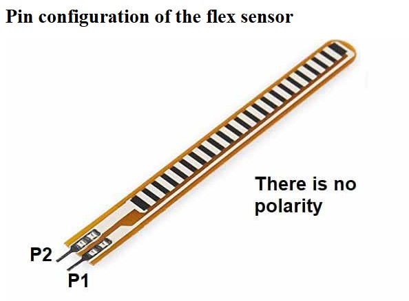
I kept it simple this week by adding an output to my already created board from week 9. I decided to use a Flex Sensor by Spectra Symbol as my input component.
At one point during my final project planning I debated trying to connect a flex sensor or possibly conductive rubber internally for my stringing system. My thought process was that I could turn pulling on things like the hands or feet into possible interactivities with the robot. I had played with the flex sensor a couple times by attaching it to a small cut off of my elastic but I really couldn't get it to flex enough for a readout. Stretching the elastic string in the doll body isn't really meant to happen often and it's meant to be in tension for stability, so in the end, I don't think the interactivity element would work for my final project.
The sensor has two leads, one to connect to power and one to connect to an analog pin. The sensor also needs a 10K Ohm resistor split between the data pin and ground. The 10k ohm resistor is very important, because it acts as a voltage divider.
The sensor works as an input by reading the bend amount, and you can see the value of the bend in the monitor. By knowing the value of the sensor when unbent versus bent in each direction, you can use a simple statement to have an output respond to different amounts of bending. The bend values seen in the monitor are derived from the voltage divider formed by the flex sensor and the 10k ohm resistor. The bend values will change either higher or lower depending on the direction of the bend.
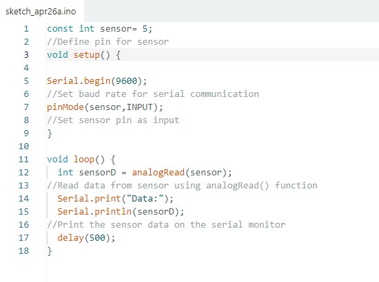
I found a very simple code for this sensor on this website. This page is also very helpful with learning more about this type of sensor and wiring the pins. I connected my flex sensors right leg into the Analogue 0 pin on my ESP32-C6 and I connected the left leg into power. I connected the resistor into the same Analogue 0 pin as the flex sensor and the other end of the resistor is in ground. I copy and pasted the sample code from the site and adjusted the pin locations in the code to match my wiring and gave it a test run.
I was able to flex the sensor and see the readout change in the serial monitor. When the sensor is straight, it shows a value around 300 and drops as low as 100 and goes as high as 1000 when bent in either direction. Now the next step is to add in my output, which will be an LED strip, and update the flex sensor code to change the color of the RGB strip depending on the bend of the sensor.
Adding an Output
RGB LED Strip
My goal was to have the LED strip change colors when specific bend thresholds were met. When the sensor is flexed low the LED strip will glow red, and when the sensor is flexed high the LED strip will glow green. When the sensor is untouched the LED strip will glow blue.
- Green = High Bend
- Red = Low Bend
- Blue = No Bend
Getting it all wired up on my breakout board was a little bit tricky since I had to get one leg of the 10k resistor and one lead of the sensor pin in the same header.
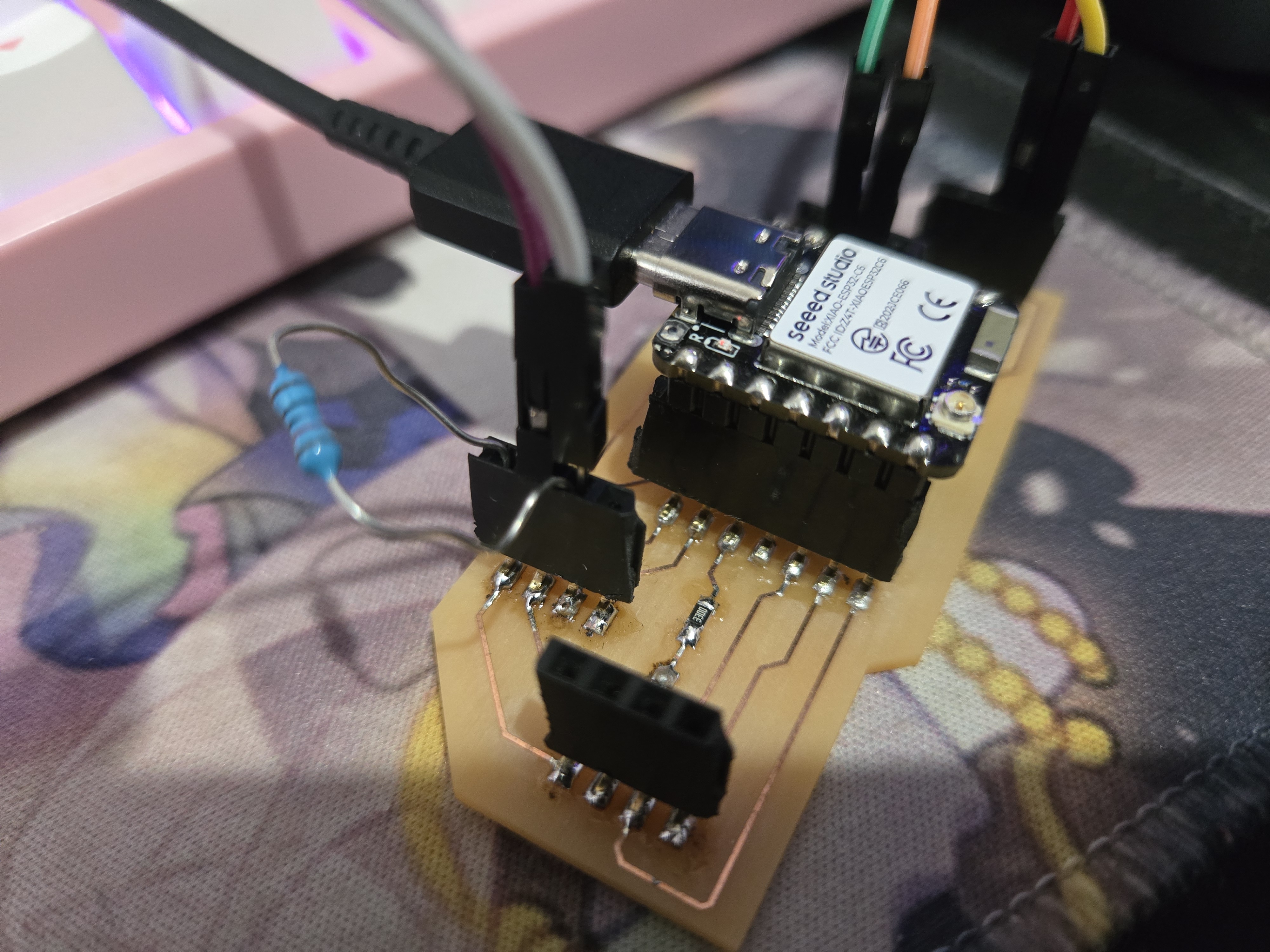
I managed to pop the header off twice in the process, but nothing a little solder can't fix. And thankfully, I didn't burn any pads off in the process of fixing it over and over.
I pulled up my code from my week 9 flex sensor and single LED. I used this code as a basis for my RGB LED strip code.
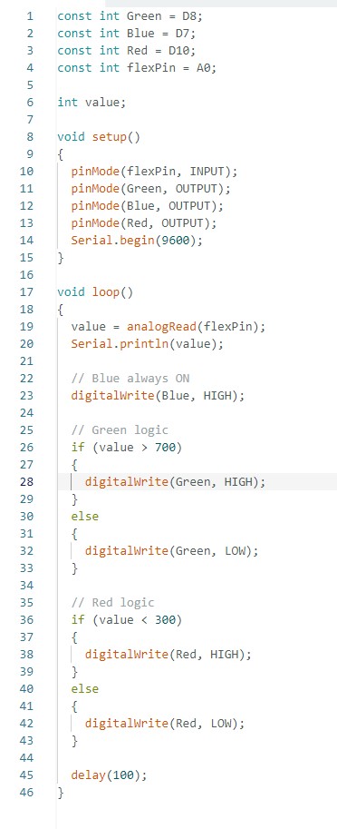
Each color in the LED strip needed their own pin and code commands. One for red, one for green, and one for blue.
- Green = D8
- Red = D10
- Blue = D7
- Flex Sensor = A0
Wiring Diagram and Build on my Board
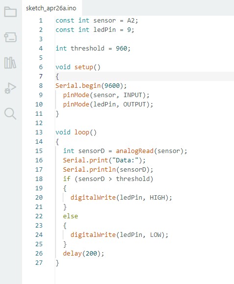
The wiring diagram below shows how the flex sensor, the RGB LED Strip, and the 10k ohm resistor are connected to the custom board that I made in week 9. The code below shows how I set up the code to read the flex sensor and turn on the LED light when the sensor is bent past a bend value of 700.
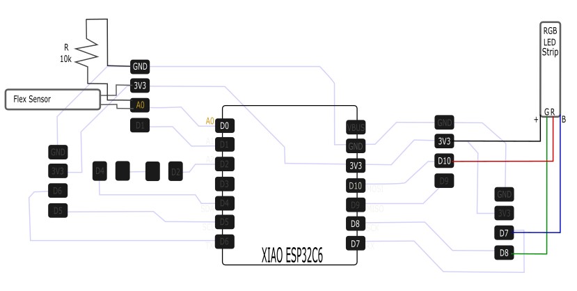
I then made an if/else statement which stated to keep the lights blue when not flexed, red if the flex value is under 300, and green if the flex value is over 700.
The code seemed good in theory and I was pretty confident it would work, but instead, my LED strip was showing all the wrong colors. Blue was always on causing some weird color effects. Green and red were not turning on as expected with the thresholds, they were actually turning on opposite what I expected.
My first thought was to check the wiring, then the code. The wiring was fine and the code matched the wiring. So I was a little confused why my colors were backwards and turning on/off at the wrong thresholds. I played with the code and realized that the on/off for this strip was backwards from the LED I blinked with the sensor in week 9.
I needed to swap the High and Low commands in my code.
LOW is: ON
HIGH is: OFF
With the High and Low swapped, I had a working build!
Week 10 Files
In my repo is a zip folder containing files for my week 10.
What files are inside my Folder:
My final (working) Flex Sensor and LED Strip code
Download My Week 10 Project Files Zip Folder