Week 9
Check List
This week's project requirements:- Probe an input device(s)'s analog levels and digital signals
- As a minimum, you should demonstrate the use of a multimeter and an oscilloscope
- Document the workflow for sending a PCB to a boardhouse
- Document your work on the group work page
- Reflect on what you learned on your individual page
Individual Assignment:
- Measure something: Add a sensor to a microcontroller board that you have designed and read it
- Document the process
Images/Files:
- Include your original design files
- Properly compress or use a zip folder if needed
- Include hero shots of your results
Group Assignment:
Resources and Helpful Links
- KiCAD
- MakeraCAM
- Carvera
- ChatGPT
- Getting started with ESP32: Button Tutorial
- MakeraCAM Workflow
- Image of the XIAO ESP32-C6 Board Pins
- Helpful People:
- My Group Partners Camille, Kim, and Dorian
- My Group Partners Camille, Kim, and Dorian
Learning Outcomes
- Demonstrate workflows used in sensing something with input device(s) and MCU board
Group Work
My Contribution to the Group Work
My group got right to work setting up our custom boards with some sensors. We used the logic analyzer that we learned how to use in week 6 and a breadboard setup with an LED, a resistor, an ESP32-C6 and two copper plates connected with aligator clips. My group worked together to get working code, troubleshoot our board set up, and finally getting a readout for our copper plate pressure sensor.
I really liked this weeks group project, as it showed me an interesting and unexpected way that I make a sensor for my robot project.
-
My Contributions to this week:
- I worked with Kim to troubleshoot our code for the copper plate pressure sensor.
- I tested the new code by pressing one of the copper plates and Camiles hand, while Camile had her other hand on the other copper plate. We made a human circuit and were able to see the readout change in the serial monitor.
- I took documentation photos for our group site.
For a more in depth look at my groups week 9 assignment, see my groups Week 9 page.
Introduction
I really enjoyed this week and I learned some really interesting and new things between my group work and my individual work. I am excited to explore the copper plate pressure sensors more as a possible additition to my final project, and I am excited to further explore the Serial Plotter feature in Arduino IDE.
Creating the Board
Adding FabLab Library
I created a breakout style board so that I could continue to use my board for multiple tests as I try different sensor options for my final project. The board I made in week 8 is only easily usable to light the soldered on LED, which is on backwards so thats not really even effective. I didn’t want to have to keep creating a new board for each thing I wanted to test, so I designed a new one with multiple uses in mind.
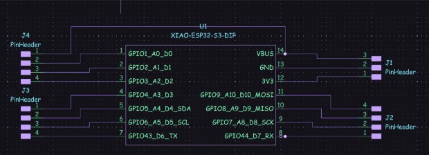
I started by designing the board to have 4 sets of header pins, but I was having trouble getting a ground connection to make sense.
I had turned to ChatGPT for some assistance and it gave me a few things to fix. It didn’t like that I had mixed sets of headers with J1 being a set of 3 and the rest being sets of 4. It didn’t like that I did not have ground or power going to J2 and J3, it also didn't love how I connected J4 to power. It also said to not use the 5V pin and to instead connect the 3V pin for everything. At this time, ChatGPT also told me to create Net Labels.
I made the suggested corrections and got the design below which I asked my ChatGPT to look over for me.
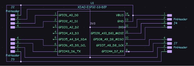
In this version it still had a few suggestions for me to fix. It was happier that I was being consistent with 4 Pinheaders in each group, but it did not like how I had everything wired together in my attempt to create ground and 3V connections.
I tried using the Net Labels like it suggested, but I was obviously not doing it correctly, because it once again told me to use Net Labels. When I created my GND and 3V3 labels I was just kind of placing them as nodes in my wires and connecting everything to the label.
I didn’t really understand what a net label did, and I was obviously using it wrong since it was correcting me, so I asked ChatGPT to explain it to me in more depth. This is when I learned that a net label is basically just a name for a wire connection. You can create the label and then any wires you label with that name become connected even if you can’t see the wire connection. This is also when I learned that I was supposed to just place the label where I wanted that wire connection to be.
Not being able to see the wire connections felt strange to me and I was a bit skeptical about how it was going to work when I got to the PCB editor, but I was pleasantly surprised when it worked.
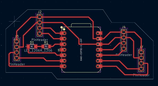
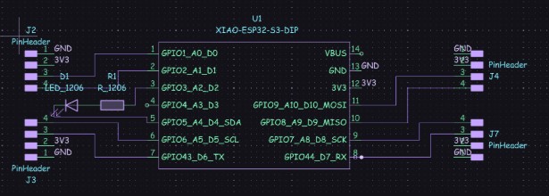
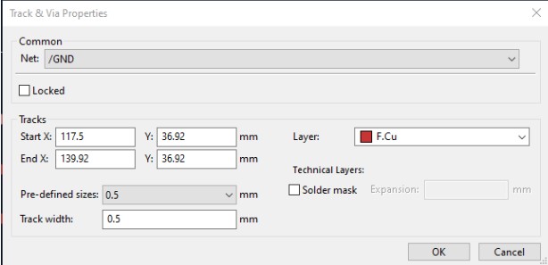
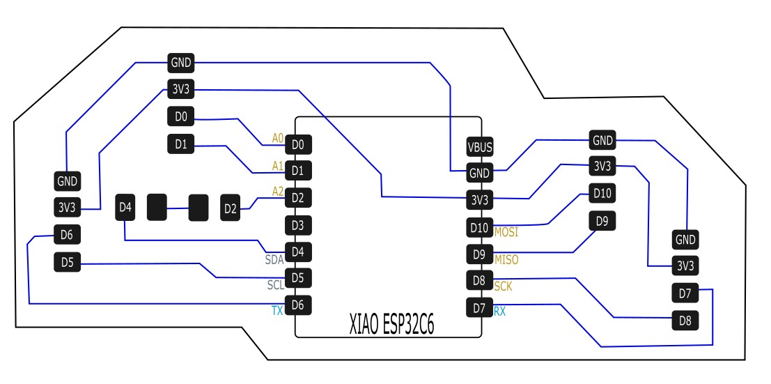
So in my final design, each of my breakout sets had a connection to ground, the 3V3 pin, and 2 data pins on the board. I threw in an LED and a resistor on the open pins I didn't connect anything to, and I kept the 5v pin unused. I also made my trace size to be 0.5mm for all of my traces so that I wouldn't have the issue I had with the week 8 board.
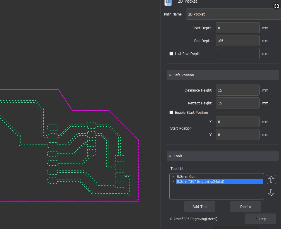
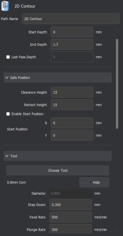
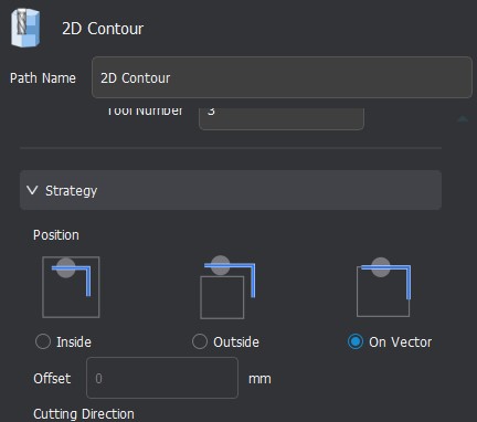
Using MakeraCAM
After exporting my .nc files from KiCAD, I opened them up in MakerCAM to get set up for milling. I once again followed the step by step instructions provided by Mr Dubick that we were given during week 8’s lesson.
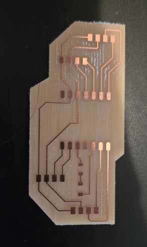
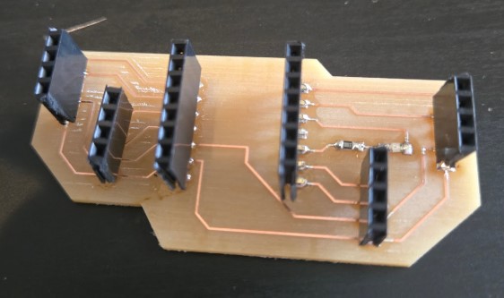
Milling my Board
I successfully milled my board in one attempt on the CarveraCNC. This is what my week 9 board looks like after milling and before the headers are soldered on. I am quitre pleased with this baord design and how it turned out after milling. I am hopeful that this deisgn will allow me to use it for multiple tests as I try out different sensors for my final project.
Soldering my Board
Like week 8, I still didn't enjoy surface mount soldering, but at least this time I was more careful about putting in the LED. I followed the same steps I outlined in week 8 when I was soldering my week 8 test board.
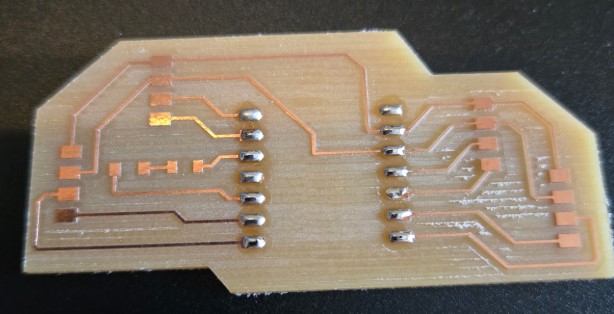
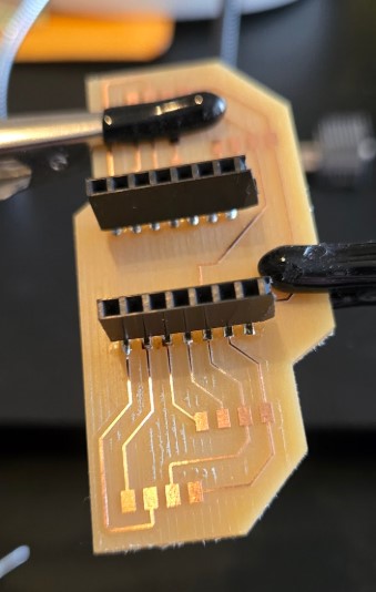
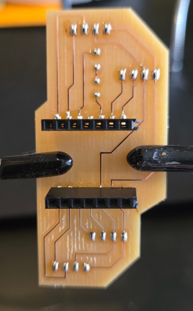
My Final Board
This is my final board after soldering on all of the headers.
Adding an Input Sensor
I was having issues with powering any boards for about two weeks from my computer. I had done a variety of tests and figured out that the issue was with my USB dock. After realizing the usb docker was the cause of my problem, I knew I needed a break and a new USB docker. I put this week on hold for about a week or two and finally came back to it to finish it correctly. I switched out the bad usb dock for a brand new one that I ordered as a replacement, and I was ready to give it another try.
I decided to use the flexsensor I had been playing with to possibly use in my final project. To use the flex sensor though, I needed an Analogue pin. All of my analogue pins were on a header that broke off sometime between weeks 8 and 9. Since I had put this week on a pause, you may notice in my week 10 page, that I had fixed the broken header pin during week 10.
Flex Sensor
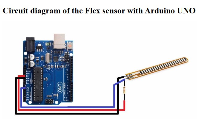
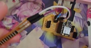
I used a Flex Sensor by Spectra Symbol as my input component.
The sensor has two pins, the left one is used for power. The Right pin needs to be in an Analog Pin. I used Analogue pin 0 on my ESP32-C6.
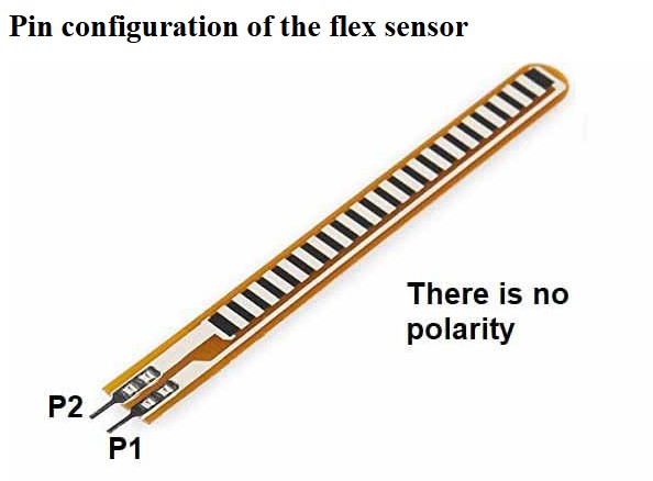
This is important, because the sensor will still look like its working in the serial monitor even if you use a different pin. But in reality, the values are very high and no noticable change happens when bent.
The sensor also needs a 10K Ohm resistor split between the data pin and ground. The 10k ohm resistor is very important, because it acts as a voltage divider. While I had been fiddling with the sensor I initially tried using it without the resistor. My values were very high, in the 4000's and bending didn't make any noticable change over the noise in the sensor. When I tested with 1k and 2k ohm resistors my values dropped to the 1000's but had minimal to no change when bending. It wasn't until I put in the 10k ohm resistor did my values drop to the 300s and have significantly noticable changes when bent.
But what do these values actually mean? The output values are a representation of the resistance of the sensor, which changes as the sensor is bent. The resistance changes either higher or lower depending on the direction of the bend. However, this is not a raw resistance value. It is a value that is derived from the voltage divider formed by the flex sensor and the 10k ohm resistor. In this case, when the sensor is straight, it has a resistance that corresponds to a value around 300 and drops as low as 100 and goes as high as 1000 when bent in either direction.
I completed all of these tests on a breadboard, before I wired it up to my custom milled board.
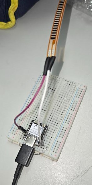
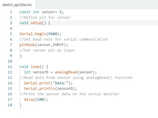
To ensure I had the sensor connected I used a basic example code to test it working. I found a very simple code for this sensor on this website. This page is also very helpful with learning more about this type of sensor and wiring the pins. I copy and pasted in the code and adjusted my pin locations and gave it a test run. As shown in the serial monitor image below, the values are static areound 300 (minus some noise) when the sensor is straight, and they increase or decrease depending on which direction the sensor is bent.
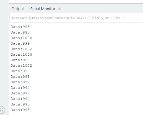
I was able to flex the sensor and see the readout change in the serial monitor.
Wiring Diagram and Build on my Board
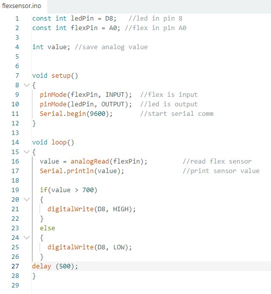
After wiring the flex sensor up and testing that it works, I added in a basic LED to pin 8 and I was ready to move forward. The wiring diagram below shows how the flex sensor, the LED, and the 10k ohm resistor are connected to the custom board. The code below shows how I set up the code to read the flex sensor and turn on the LED light when the sensor is bent past a bend value of 700.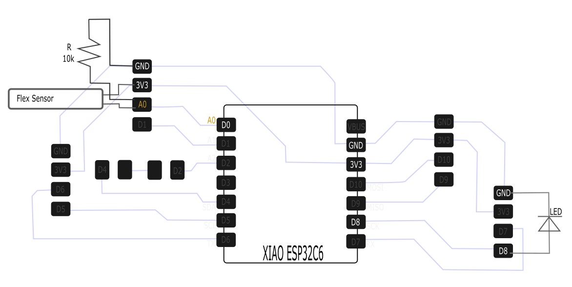
Week 9 Files
In my repo is a zip folder containing files for my week 9.
What files are inside my Folder:
My KiCAD files for my week 9 board
My Arduino Code for my Flex-LED Control
Download My Week 9 Project Files Zip Folder