16. System Integration
Robot Arm Lamp System Integration Plan
Project Title: Robot Arm Lamp inspired by Pixar Luxo Jr.
Assignment checklist
- Made a plan for system integration
- Documented plan with CAD and/or sketches
- Implemented and documented packaging methods
- Designed final project to look like a finished product
- Linked from final project page
Completed Build
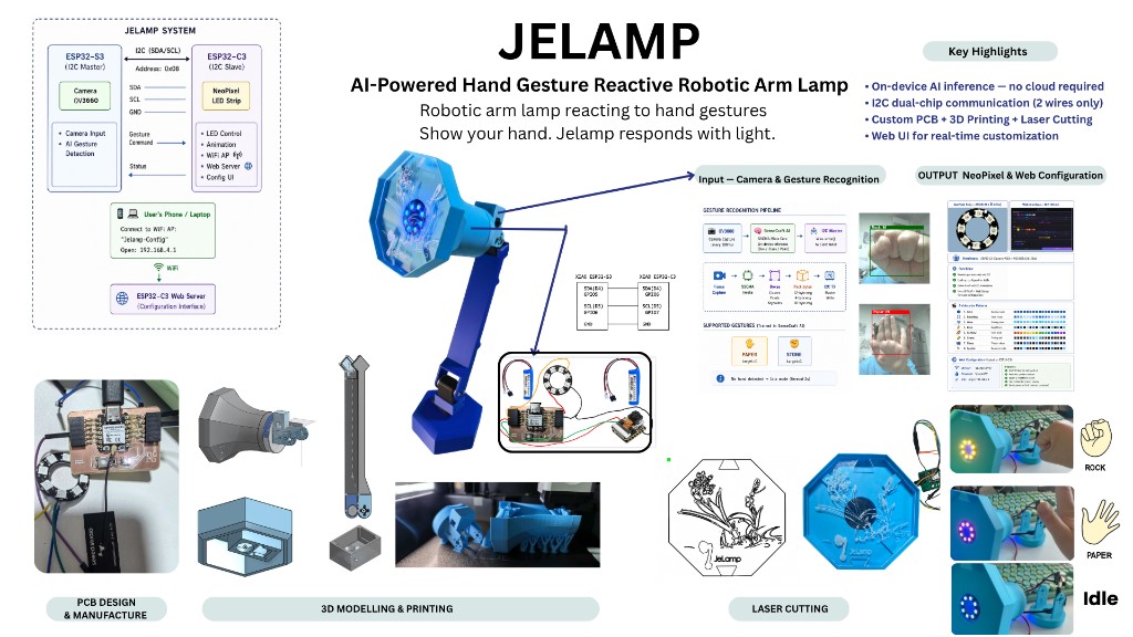
My final project, JeLamp, is an interactive desk lamp inspired by Pixar Luxo Jr. It combines practical lighting with on-device vision and programmable NeoPixel expressions. The arm is a fixed mechanical structure — three STS3215 housings serve as joint connectors only.
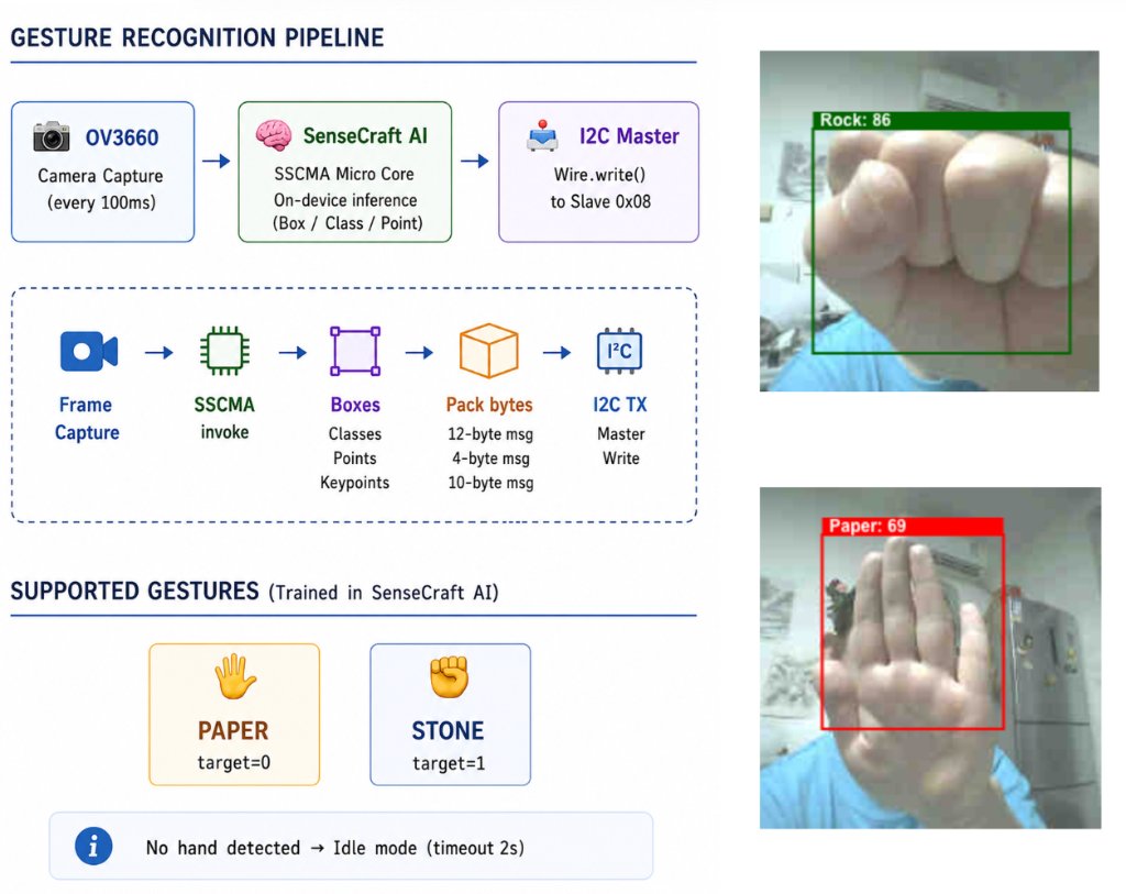
The primary interaction is a paper / stone gesture game: the XIAO ESP32-S3 Sense camera runs a pretrained hand-gesture model from SenseCraft AI, recognizes the user's hand shape, and sends results over I2C to a custom Week 8 PCB with an ESP32-C3, which drives NeoPixels to change color and animation pattern. The C3 board also hosts a Wi-Fi web interface for manual control.
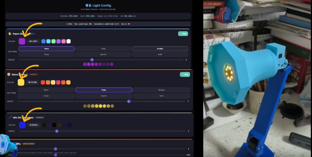
Assembled JeLamp during integrated testing (left: web UI config; right: lamp head showing stone response). Project overview poster from the final project page.
Integrated Build Evidence
Photos below are from the completed build documented on the final project page — wired boards, cable routing, mechanical assembly, and end-to-end gesture demo.
Week 8 custom PCB (populated and tested) and lamp head sub-assembly with I2C wiring.
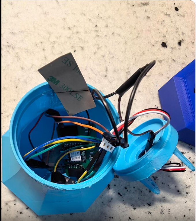
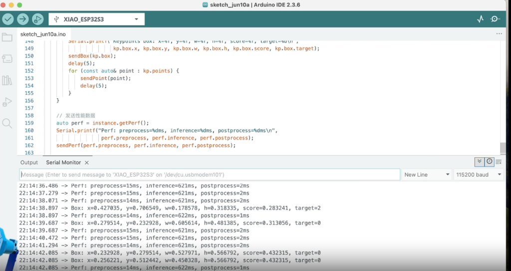
I2C cable routed through the hollow base and arm (left); pre-assembly bench test with Serial Monitor (right).
End-to-end demo video (~1 min): fabrication, gesture recognition, and lighting response. Also on the final project page.
Final Project Timeline
This timeline shows the planned milestones for completing the final project, from system integration planning to fabrication, assembly, testing, and final documentation.
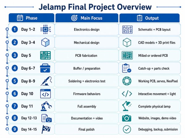
Final project timeline showing the planned milestones and deadlines.
System Architecture
The planned system uses a dual-MCU architecture: a standalone XIAO ESP32-S3 Sense in the base handles vision and WiFi; a custom PCB with ESP32-C3 handles NeoPixel lighting. The two communicate over I2C. Power comes from a 5 V USB-C supply.
Planned system block diagram for power, control, sensing, actuation, and interface.
                    +---------------------------+
                    |   User (hand gesture)     |
                    +-------------+-------------+
                                  |
                                  v
+------------------------------------------------------------------+
|  MASTER: XIAO ESP32-S3 Sense  (mounted in base)                  |
|  - OV2640 camera capture                                         |
|  - SenseCraft AI pretrained gesture model (Rock / Paper / Scissors)|
|  - I2C Master  SDA=GPIO8, SCL=GPIO9  ->  sends gesture code      |
|  - WiFi web UI (Week 15)                                         |
+----------------------------+-------------------------------------+
                             | I2C (400 kHz, 3-wire: GND, SDA, SCL)
                             v
+------------------------------------------------------------------+
|  SLAVE: ESP32-C3  (Custom NeoPixel PCB)                          |
|  - I2C Slave address 0x08                                         |
|  - Receives gesture ID -> selects NeoPixel color + pattern        |
|  - Drives WS2812B ring/strip in lamp head                        |
+------------------------------------------------------------------+

Gesture flow:
  Camera frame -> SenseCraft inference -> gesture label
       -> I2C write(gesture_id) -> NeoPixel color + pattern update
Subsystem Map
| Subsystem | Components | Related Fab Academy Week |
|---|---|---|
| Structure | 3D printed joints and arms, laser-cut base details | Week 3, 5, 8 |
| Controller | XIAO ESP32-S3 Sense (camera, WiFi, I2C master) | Week 4, 11 |
| Lighting PCB | Custom ESP32-C3 board, NeoPixel driver, I2C slave | Week 6, 8 |
| Input | OV2640 camera (gesture), optional touch pad | Week 11, 17 |
| Vision AI | SenseCraft AI pretrained hand-gesture model on ESP32-S3 | Week 17 |
| Output | NeoPixel ring | Week 12 |
| Communication | I2C master/slave, WiFi | Week 13 |
| Interface | Web-based control panel + gesture game mode | Week 15 |
| Integration | Dual-board wiring, packaging, calibration, final assembly | Week 16 |
Gesture Interaction: Rock–Paper–Scissors
The lamp's primary interactive demo is a rock–paper–scissors game. The user shows a hand gesture in front of the camera; the lamp detects it and updates the NeoPixel light to express the result. This ties together vision and lighting in one integrated behavior.
Interaction Flow
| Step | Action | Subsystem |
|---|---|---|
| 1 | User raises hand in camera view; lamp pulses white via NeoPixel (I2C). | Camera, NeoPixel (via I2C) |
| 2 | User holds rock, paper, or scissors for ~1 s; SenseCraft model classifies the gesture. | ESP32-S3 + SenseCraft AI |
| 3 | ESP32-S3 sends gesture ID over I2C to the lighting board. | I2C master |
| 4 | ESP32-C3 receives gesture ID and switches NeoPixel color and animation pattern. | ESP32-C3 NeoPixel PCB |
| 5 | Lamp holds the result light for 3 s, then returns to idle pulse. | State machine on ESP32-S3 |
Gesture → Light Response Mapping
| Gesture | NeoPixel Color | Pattern |
|---|---|---|
| Rock | Warm amber (255, 140, 0) | Solid, high brightness |
| Paper | Cool white-blue (180, 220, 255) | Slow breathing fade |
| Unknown / no hand | Dim warm white (80, 60, 40) | Idle pulse |
SenseCraft AI Vision Pipeline
Instead of training a custom model from scratch (as in my Week 17 Edge Impulse facial expression work), the final project will use a pretrained hand-gesture model from SenseCraft AI on the XIAO ESP32-S3 Sense. SenseCraft provides ready-to-flash models for common ESP32 boards and handles camera init, inference, and serial output in one package.
SenseCraft AI deployment workflow (planned):

1. Open SenseCraft AI Model Assistant
2. Select board: XIAO ESP32-S3 Sense
3. Choose pretrained model: Hand Gesture Recognition (Rock / Paper / Scissors)
4. Flash model to board via USB
5. Verify Serial output shows gesture labels with confidence scores
6. Integrate inference results into JeLamp firmware:
     - Read gesture label from SenseCraft inference API / serial bridge
     - Map label -> GESTURE_ROCK (0x01), GESTURE_PAPER (0x02), GESTURE_SCISSORS (0x03)
     - Trigger I2C write on stable detection (confidence > 0.75)
SenseCraft Integration Checklist
- Flash SenseCraft gesture model and confirm Serial labels: rock, paper, scissors.
- Test at 30–60 cm distance with plain background and good lighting.
- Add debounce: require the same label for 5 consecutive frames before acting.
- Merge SenseCraft inference loop with existing WiFi + I2C code on ESP32-S3.
- On gesture confirmed, call
sendGestureOverI2C(gesture_id).
I2C Communication: ESP32-S3 Master ↔ ESP32-C3 Slave
Lighting is handled on a separate custom PCB so NeoPixel timing (RMT / bit-banging) does not interfere with camera capture and AI inference on the ESP32-S3. The XIAO exposes I2C on GPIO8 (SDA) and GPIO9 (SCL); a 3-wire cable (GND, SDA, SCL) runs up through the hollow arm to the lamp head. Each board is powered locally — the XIAO via USB-C in the base, the ESP32-C3 from the 5 V NeoPixel rail on its own PCB.
Hardware Connection
XIAO ESP32-S3 Sense (base)                NeoPixel PCB (ESP32-C3)

GND  ------------------------------------>  GND
D4 / GPIO8 (SDA) ----------------------->  GPIO6 (SDA)
D5 / GPIO9 (SCL) ----------------------->  GPIO7 (SCL)

Cable: 3-wire silicone ribbon (GND, SDA, SCL), ~400 mm through lower + upper arm
Power: separate — XIAO via USB-C in base; ESP32-C3 from 5 V on NeoPixel PCB
Pull-ups: 4.7 kΩ on SDA and SCL to 3V3 (on NeoPixel PCB only)
I2C Protocol (planned)
| Field | Value | Description |
|---|---|---|
| Slave address | 0x08 | ESP32-C3 NeoPixel controller |
| Bus speed | 400 kHz | Fast-mode I2C |
| Write packet | 2 bytes | [command, value] |
| CMD_GESTURE | 0x01 | value = 0x01 rock, 0x02 paper, 0x03 scissors |
| CMD_BRIGHTNESS | 0x02 | value = 0–255 |
| CMD_PATTERN | 0x03 | value = 0 solid, 1 breathe, 2 chase, 3 rainbow |
| CMD_PING | 0xFF | value = 0x00; slave responds with ACK byte 0xAC on request |
Firmware Snippets (planned)
ESP32-S3 — I2C master (gesture sender):
#include <Wire.h>

#define I2C_SDA  8
#define I2C_SCL  9
#define NEO_SLAVE  0x08

#define GESTURE_ROCK      0x01
#define GESTURE_PAPER     0x02
#define GESTURE_SCISSORS  0x03
#define CMD_GESTURE       0x01

void sendGestureOverI2C(uint8_t gesture) {
  Wire.beginTransmission(NEO_SLAVE);
  Wire.write(CMD_GESTURE);
  Wire.write(gesture);
  Wire.endTransmission();
}

void onGestureDetected(const char* label) {
  if (strcmp(label, "rock") == 0) {
    sendGestureOverI2C(GESTURE_ROCK);
  } else if (strcmp(label, "paper") == 0) {
    sendGestureOverI2C(GESTURE_PAPER);
  } else if (strcmp(label, "scissors") == 0) {
    sendGestureOverI2C(GESTURE_SCISSORS);
  }
}
ESP32-C3 — I2C slave (NeoPixel driver):
#include <Wire.h>
#include <Adafruit_NeoPixel.h>

#define NEO_PIN     2
#define NUM_PIXELS  12
#define I2C_ADDR    0x08

Adafruit_NeoPixel pixels(NUM_PIXELS, NEO_PIN, NEO_GRB + NEO_KHZ800);

uint8_t rxBuf[2];
uint8_t rxLen = 0;

void receiveEvent(int len) {
  rxLen = 0;
  while (Wire.available()) rxBuf[rxLen++] = Wire.read();
}

void applyGesture(uint8_t gesture) {
  switch (gesture) {
    case 0x01: setPatternSolid(255, 140, 0);   break;  // rock
    case 0x02: setPatternBreathe(180, 220, 255); break;  // paper
    case 0x03: setPatternChase(255, 0, 80);    break;  // scissors
  }
}

void setup() {
  pixels.begin();
  pixels.setBrightness(180);
  Wire.begin(I2C_ADDR);
  Wire.onReceive(receiveEvent);
}

void loop() {
  if (rxLen >= 2 && rxBuf[0] == 0x01) applyGesture(rxBuf[1]);
  updatePattern();  // non-blocking animation tick
}
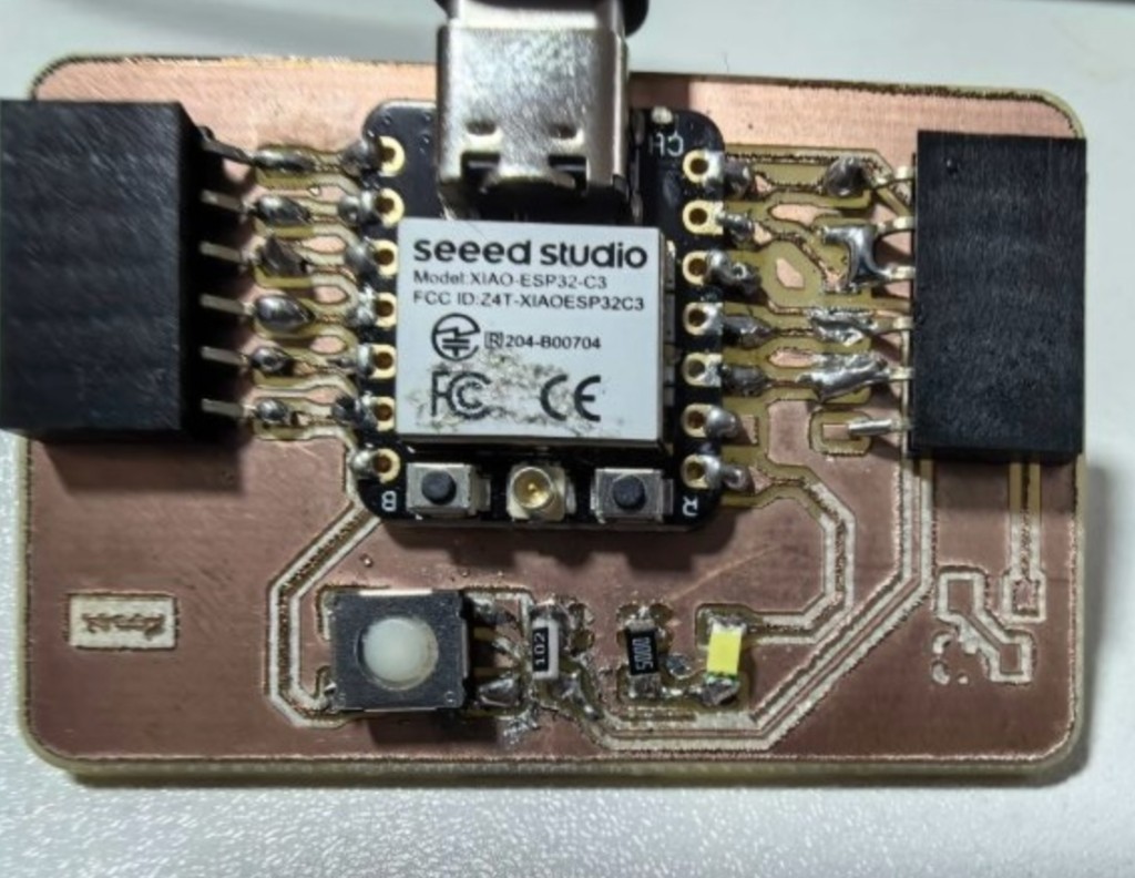
Custom ESP32-C3 NeoPixel PCB
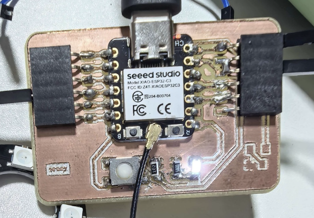
This is the only custom PCB in the system — designed in KiCad (Week 6), milled and soldered (Week 8), then mounted in the lamp head as the I2C slave and NeoPixel driver. Full fabrication documentation is on the final project page.
Mechanical Integration
The lamp body uses a fixed giraffe-like arm structure. The base contains the XIAO ESP32-S3 Sense and ballast weight; the arm sections are hollow so the I2C and power cables can pass through to the lamp head.
Mechanical assembly — lamp head sub-assembly (left) and base with ESP32-S3 module mounted (right).
3D Printed Parts
| Part | Material | Approx. Print Time | Notes |
|---|---|---|---|
| Base bottom | PLA | 3 h | 30% infill, slot for XIAO module and ballast |
| Base top cover | PLA | 2 h | Touch area and cable pass-through |
| Lower arm | PLA | 2 h | Hollow 150 mm tube, 3 mm wall |
| Upper arm | PLA | 1.5 h | Hollow 120 mm tube, 3 mm wall |
| Neck / head mount | PLA | 1 h | Holds lamp shade and camera angle |
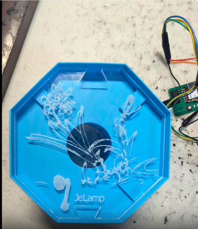
| Lamp shade | White PLA | 2 h | Conical shade, 80 mm opening |
| Diffuser | Frosted acrylic, 3 mm | Laser cut | Press-fit into lamp shade |
Cable Routing
Cable routing was one of the most important integration risks in this design. A 3-wire I2C cable (GND, SDA, SCL) runs from the base through the hollow arm to the ESP32-C3 NeoPixel board in the lamp head. Each board is powered locally — the XIAO via USB-C in the base, the C3 from the 5 V rail on its PCB.
I2C cable (red / white / black) routed through the base lid opening with ~15 mm slack before entering the arm.
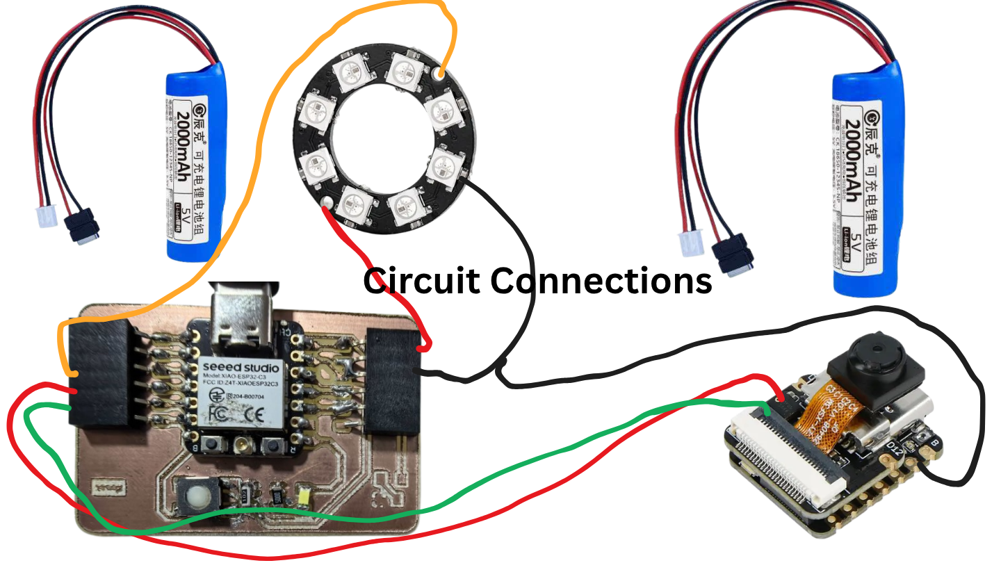
I2C wiring reference — SDA, SCL, and GND between the two XIAO modules.
Cable Protection Rules
- Use flexible silicone wire instead of stiff PVC wire.
- Leave about 15 to 20 mm slack at the arm-to-head joint.
- Keep I2C wires twisted and away from the 5 V power line.
- Use heat-shrink tubing at cable entry and exit points.
Electronics Integration
The system uses one off-the-shelf controller and one custom PCB. The XIAO ESP32-S3 Sense mounts in the base with its built-in camera and USB-C port exposed for programming. The ESP32-C3 NeoPixel PCB mounts in the lamp head and drives the WS2812B ring. A 3-wire I2C cable (GND, SDA, SCL) runs through the hollow arm to connect them.
Populated C3 PCB (left) and pre-enclosure bench test showing SenseCraft inference over I2C (right).
XIAO Module (Base)
ESP32-S3 Sense: camera, SenseCraft AI, WiFi, I2C master on GPIO8/9 (D4/D5).
NeoPixel PCB (Head)
ESP32-C3-MINI-1: I2C slave at 0x08, NeoPixel RMT output, mounted behind the lamp shade with short data wire to the LED ring.
I2C Link
400 kHz, 4.7 kΩ pull-ups, GND/SDA/SCL through the arm. Test with ping command before closing the enclosure.
Power Budget
| Component | Voltage | Max Current | Power |
|---|---|---|---|
| ESP32-S3 with WiFi | 3.3 V | 350 mA | 1.2 W |
| ESP32-C3 + NeoPixel full brightness | 5 V | 500 mA estimated | 2.5 W |
| Camera module | 3.3 V | 100 mA | 0.3 W |
The planned supply is a 5 V 2 A USB-C power adapter connected directly to the XIAO and NeoPixel PCB. A 470 µF capacitor near the NeoPixel connector absorbs current spikes during color changes.
Software Integration
The firmware is split across two MCUs and organized in layers on the ESP32-S3. Each subsystem will be tested independently — SenseCraft gesture detection alone, I2C ping alone, NeoPixel patterns alone — before the full rock–paper–scissors game is integrated.
ESP32-S3 (Master) — Layered Firmware

Layer 4: Interaction Modes
  Gesture game (rock/paper/scissors), web UI control, touch response, idle behavior

Layer 3: SenseCraft AI Bridge
  Camera capture -> pretrained gesture model -> debounced label output

Layer 2: Device Drivers
  SenseCraft inference, I2C master (Wire), WiFi WebServer, touch read

Layer 1: Hardware Abstraction
  I2C at 400 kHz, camera init (OV2640)


ESP32-C3 (Slave) — Lighting Firmware

  I2C slave handler -> gesture/pattern lookup table -> NeoPixel RMT driver
  Non-blocking animation engine: solid, breathe, chase, rainbow
Key Firmware Structure
#include <WiFi.h>
#include <WebServer.h>
#include <Wire.h>

#define I2C_SDA   8
#define I2C_SCL   9
#define TOUCH_PIN 6

#define NEO_SLAVE  0x08
#define GESTURE_ROCK      0x01
#define GESTURE_PAPER     0x02
#define GESTURE_SCISSORS  0x03
#define CMD_GESTURE       0x01
Integrated Behaviors
| Planned Behavior | What It Should Do | Integrated Subsystems |
|---|---|---|
| Rock–paper–scissors game | Detect user gesture via SenseCraft; NeoPixel shows result color/pattern via I2C. | Camera, SenseCraft AI, I2C, ESP32-C3 NeoPixel |
| Wake up | Lamp sends I2C brightness fade-in command on power-on. | I2C to NeoPixel PCB |
| Work mode | Sets warm white solid light at full brightness. | I2C brightness, web UI |
| Sleep mode | Slowly pulses at low NeoPixel brightness. | State machine, I2C pattern command |
| Touch response | A touch on the base cycles light modes or triggers the gesture game. | Touch input, state machine |
| Web control | A browser can trigger the gesture game and override light color/brightness. | WiFi AP, WebServer routes, I2C master |
Web Interface Routes
| Route | Method | Purpose |
|---|---|---|
| / | GET | Serve the control panel page. |
| /gesture | POST | Start or stop gesture game mode. |
| /led | POST | Change LED brightness from 0 to 255. |
| /color | POST | Set RGB color via I2C to NeoPixel board. |
| /pattern | POST | Set animation pattern: solid, breathe, chase, rainbow. |
Packaging
The packaging goal is to make the lamp look like a finished consumer product instead of a loose prototype. The planned design will hide wires, PCB, and solder joints while keeping the lamp serviceable.
Functional Layer
XIAO module mounted in the base; NeoPixel board mounted in the lamp head with a heat spreader.
Structural Layer
3D printed shells will enclose the mechanisms, route cables through hollow arms, and hold joints with M3 fasteners.
Finish Layer
Sanded surfaces, a consistent white or gray finish, frosted acrylic diffuser, and anti-slip silicone feet.
Interaction Layer
Touch-sensitive base area, accessible USB-C port, rear power jack, and small visible status LED.
Base Interior Layout
Top view, base cover removed

+--------------------------------------+
|                                      |
|   XIAO ESP32-S3 Sense module         |
|   USB-C accessible at rear           |
|             |                        |
|             | I2C + power cables up  |
|                                      |
|   Steel ballast plate, about 200 g   |
|                                      |
|   5 V USB-C power at rear            |
+--------------------------------------+
Lamp Head Detail
The lamp head contains the ESP32-C3 NeoPixel PCB, the WS2812B LED ring, a small aluminum plate for heat spreading, and a frosted acrylic diffuser press-fit into the shade rim. The I2C and 5 V power cable enters from the upper arm through a grommet. Keeping the NeoPixel controller close to the LEDs minimizes data-line length and improves timing reliability.
Planned Assembly Process
I will assemble the system in stages, testing each layer before hiding it inside the final enclosure. This should make it easier to identify whether a problem comes from electronics, wiring, mechanical constraints, or software calibration.
Step 1: Electronics Preparation
- Connect XIAO ESP32-S3 Sense via USB-C and flash basic WiFi + I2C test firmware.
- Solder the ESP32-C3 NeoPixel PCB and flash I2C slave + rainbow test sketch.
- Connect the two boards with a bench I2C cable; verify ping (0xFF) returns ACK (0xAC).
- Flash SenseCraft AI hand-gesture model to XIAO; confirm rock/paper/scissors Serial output.
- Test end-to-end: show gesture -> I2C command -> NeoPixel color change.
Step 2: Mechanical Assembly
- Mount the XIAO module in the base with M2 screws; keep USB-C port accessible.
- Place the ballast weight in the base.
- Assemble lower arm, upper arm, neck, and lamp head from bottom to top.
- Press-fit the acrylic diffuser into the lamp shade.
Step 3: Wiring and Calibration
- Route the I2C cable (3-wire: GND, SDA, SCL) and separate 5 V NeoPixel power through the arm interior.
- Mount ESP32-C3 NeoPixel PCB in the lamp head; keep NeoPixel data wire under 10 cm.
- Calibrate gesture detection distance (30–60 cm) and camera angle toward the user desk area.
- Adjust light patterns until the game feels responsive and expressive.
Step 4: Packaging and Planned Final Test
- Sand printed parts from 220 to 400 grit.
- Close the base cover and press-fit the acrylic diffuser.
- Add silicone feet and strain relief for the power cable.
- Run a cold-start test, touch test, web UI test, gesture game test, LED test, and 30-minute heat test.
Planned Bill of Materials
This is my estimated material list for the integrated prototype. The final quantities and cost may change after fabrication and assembly.
| # | Component | Spec | Qty | Approx. Cost |
|---|---|---|---|---|
| 1 | MCU module (main) | XIAO ESP32-S3 Sense | 1 | $15 |
| 2 | MCU module (lighting) | ESP32-C3-MINI-1 | 1 | $2 |
| 3 | Lighting module | WS2812B NeoPixel ring (12 LED) + ESP32-C3 PCB | 1 | $4 |
| 4 | PCB | ESP32-C3 NeoPixel PCB, self-milled FR4 | 1 | Fab Lab |
| 5 | Mechanical materials | PLA, acrylic, screws, silicone wire, heat shrink | Set | $11 |
| 6 | Power | 5 V 2 A USB-C adapter, silicone feet | Set | $5 |
| Total estimated cost | About $37 | |||
Expected Challenges and Planned Solutions
Possible problem: SenseCraft gesture model misclassifies or flickers between labels.
Planned solution: Require 5 consecutive frames with confidence above 0.75 before sending I2C command. Improve lighting and use a plain background during the game.
Possible problem: I2C communication fails on the long cable through the arm.
Planned solution: Use twisted-pair silicone wire for SDA/SCL, add 4.7 kΩ pull-ups at both ends, and keep I2C cable away from the 5 V power line.
Possible problem: The lamp may tip forward due to the long arm.
Planned solution: Add about 200 g of steel ballast inside the base and test the center of gravity.
Possible problem: The LED may become hot during longer use.
Planned solution: I will add a small aluminum heat spreader inside the lamp head and run a temperature test.
Integration Notes Before Building
- Test each subsystem before final assembly: SenseCraft gestures alone, I2C ping alone, NeoPixel patterns alone.
- The dual-MCU split keeps NeoPixel RMT timing off the ESP32-S3 so camera capture and AI inference are not interrupted.
- Cable routing is part of mechanical design. The I2C cable must pass through the hollow arm with slack at the head joint.
- Mount the camera on the base or lower arm so it faces the user at desk height during the gesture game.
Files
| File | Description | Format |
|---|---|---|
| jelamp_master.ino | ESP32-S3 firmware: SenseCraft bridge, I2C master, WiFi UI | Arduino |
| jelamp_neopixel_slave.ino | ESP32-C3 firmware: I2C slave, NeoPixel patterns | Arduino |
| jelamp-neopixel.kicad_pro | ESP32-C3 NeoPixel PCB KiCad project | KiCad 8 |
| assembly.f3d | Planned full 3D assembly | Fusion 360 |
| base_bottom.stl, base_top.stl | Planned base shell files | STL |
| lower_arm.stl, upper_arm.stl, lamp_shade.stl | Planned arm and shade files | STL |
| diffuser.dxf | Planned acrylic diffuser cutting file | DXF |
Source document: Week 16 System Integration - Robot Arm Lamp
Planning Checklist
This checklist tracks the Fab Academy system integration requirements for the final project. Items marked "Planned" or "In progress" will be updated to "Done" with photos and video after the physical build is complete.
| Requirement | Planned Evidence | Status |
|---|---|---|
| Made a plan for system integration | Dual-MCU architecture, gesture game flow, I2C protocol, assembly steps on this page | Done |
| Documented plan with CAD and/or sketches | System block diagram, side-view sketch, cable routing schematic, base interior layout, 3D parts table | Done |
| Implemented methods of packaging | Base enclosure, hollow-arm cable routing, lamp-head PCB mount, laser-cut acrylic panel — see assembly photos above | Done |
| Designed final project to look like a finished product | Blue 3D-printed shell, hidden wires and PCBs, laser-cut decorative lamp head panel | Done |
| Documented system integration of final project | This page + final project assembly section with photos and demo video | Done |
| Linked from final project page | Final Project page links to this integration documentation | Done |
Hero Shots and Demo Video
The integrated build is documented with real photos and a one-minute demo video on this page and the final project page.
Integrated system test — web UI config alongside assembled lamp responding to stone gesture.
presentation.mp4 — fabrication steps, paper/stone gesture demo, and final operation.