

Software & Tools
Arduino IDE
Used for board setup, library management, upload, and serial monitoring during device integration.
Version 2.3.7
Open Source (GNU AGPLv3)


Home Assistant
Used as the receiving platform for Zigbee data, device pairing, dashboards, and rule-based automations.
Core 2026.2.2
Open Source (Apache 2.0)

Popular Communication Methods
There is no single best communication method for every project. The right choice depends on range, speed, power consumption, wiring complexity, and whether communication happens locally, device-to-device, or through a larger network.
Before looking at the individual communication methods, it helps to understand a few core terms first. They appear throughout the comparison and make the differences between the protocols much easier to understand.
Synchronous vs. asynchronous: Imagine two people clapping to the same beat. Synchronous means both sides share a common timing signal, called a clock, so the receiver always knows exactly when a new bit of data is valid. Asynchronous means there is no shared beat. Instead, both sides agree on a speed beforehand, and start and stop markers around each byte tell the receiver when data begins and ends.
Clock signal: A clock signal is a wire that rapidly switches between high and low voltage at a fixed rhythm, like a metronome ticking. Every tick tells the receiver when a bit is ready to be read. Without a shared clock, both sides must independently count time at the same agreed speed. With a clock wire, higher speeds and more reliable transfers are possible because timing is never guessed.
Duplex: Full-Duplex means both directions work at once, like a phone call. Half-Duplex means only one side can send at a time, like a walkie-talkie. Simplex means communication only goes in one direction, like a TV broadcast where the receiver never talks back.
The methods below are the ones I find most useful to compare early in a project, because they cover the most common situations from short wired buses to direct wireless links and network-based communication.
SPI
SPI is a synchronous, full-duplex bus. One device acts as the main controller and controls the clock line. It picks which secondary device it wants to talk to by pulling that secondary device’s dedicated Chip Select (CS) pin low. Because data flows in both directions at the same time, one wire from main to secondary (MOSI) and one from secondary to main (MISO), every transfer sends and receives simultaneously, even if only one direction is relevant to the application.
Typical use cases: Fast displays, SD card modules, high-speed motion sensors, SPI flash memory chips, and DACs.
 One of the fastest communication options available, timing is completely predictable because the main controller controls the clock, it is supported by virtually every microcontroller, and it is easy to inspect with a logic analyzer.
 It needs three shared wires plus one dedicated CS wire per secondary device, so the pin count grows with each device. There is no built-in addressing, error detection, or delivery confirmation.
SPI Setup: Call SPI.begin(SCK, MISO, MOSI) in setup(). Set the CS pin as an output and pull it HIGH initially. Wrap each transfer in beginTransaction() and endTransaction() so multiple devices can safely share the bus. Match the frequency and mode in SPISettings to the secondary device’s datasheet. When unsure, start at 1 MHz with MODE0.
#include <SPI.h>

// User-specific
#define PIN_SCK 18
#define PIN_MOSI 23
#define PIN_MISO 19
#define PIN_CS 5
#define SPI_FREQ 4000000
#define SPI_MODE SPI_MODE0

struct SpiPacket {
    uint8_t cmd;
    uint8_t data[12];
    uint8_t crc;
};

SpiPacket spiTx, spiRx;

void spiTransfer(const SpiPacket& tx, SpiPacket& rx) {
    uint8_t buf[sizeof(SpiPacket)];
    memcpy(buf, &tx, sizeof(buf));

    SPI.beginTransaction(SPISettings(SPI_FREQ, MSBFIRST, SPI_MODE));
    digitalWrite(PIN_CS, LOW);
    SPI.transferBytes(buf, (uint8_t*)&rx, sizeof(buf));
    digitalWrite(PIN_CS, HIGH);
    SPI.endTransaction();
}
I2C
I2C is a two-wire bus that is half-duplex and address-based. All devices share the same two wires, SDA for data and SCL for clock. Every secondary device has a unique address, so the main device can talk to many devices using just these two lines.
Typical use cases: Environmental sensors, distance sensors, motion sensors, small OLED displays, real-time clock modules, EEPROM chips, and touch controllers.
Extremely efficient in hardware, just two wires can reach many devices, no extra pins are needed for addressing, and the majority of small sensor chips speak I2C natively.
It is much slower than SPI, half-duplex only, sensitive to line capacitance on longer wires, and address conflicts between different modules are common in practice.
I2C Setup: Call Wire.begin(SDA, SCL) in setup(). Both lines need pull-up resistors to the supply voltage. If the device address is unknown, run an I2C scanner first. Use Wire.setClock(400000) to switch from standard speed to fast mode.
#include <Wire.h>

// User-specific
#define PIN_SDA 21
#define PIN_SCL 22
#define I2C_ADDR 0x42
#define I2C_FREQ 400000

struct I2cData {
    float value;
    uint8_t status;
};

I2cData i2cTx, i2cRx;

void i2cSend(uint8_t addr, const I2cData& data) {
    Wire.beginTransmission(addr);
    Wire.write((const uint8_t*)&data, sizeof(data));
    Wire.endTransmission();
}

bool i2cReceive(uint8_t addr, I2cData& data) {
    Wire.requestFrom(addr, (uint8_t)sizeof(data));
    if (Wire.available() < (int)sizeof(data)) return false;
    Wire.readBytes((uint8_t*)&data, sizeof(data));
    return true;
}
UART
UART is one of the oldest and simplest serial protocols. Two devices connect directly to each other, with TX from one side going to RX on the other. Both devices must agree on the same baud rate, and a start bit plus optional stop bits define where each byte begins and ends.
Typical use cases: GPS modules, cellular modems, board-to-board links, Bluetooth UART bridges, debug printing to a PC terminal, and industrial RS-232 or RS-485 devices with proper level shifting.
Very simple wiring, universally supported, and extremely easy to debug with a cheap USB-serial adapter and a terminal emulator.
It is point-to-point only, has no addressing, both ends must match the exact baud rate, and packet framing must be handled in code if structured communication is needed.
UART Setup: Most boards expose multiple hardware UARTs. Keep the main USB debug serial free if possible and use a secondary port like Serial1.begin(baud, config, RX_PIN, TX_PIN). It is also good practice to include a sync byte at the start of each packet so the receiver can detect packet boundaries.
// Use Serial1 or Serial2 and keep Serial free for USB debug

#define UART_BAUD 115200
#define PIN_TX 17
#define PIN_RX 16

struct UartPacket {
    uint8_t header;
    int16_t payload;
    uint8_t checksum;
};

UartPacket uartTx, uartRx;

void uartSend(HardwareSerial& port, const UartPacket& pkt) {
    port.write((const uint8_t*)&pkt, sizeof(pkt));
}

bool uartReceive(HardwareSerial& port, UartPacket& pkt) {
    if (port.available() < (int)sizeof(pkt)) return false;
    port.readBytes((uint8_t*)&pkt, sizeof(pkt));
    return (pkt.header == 0xAA);
}
WiFi / UDP
WiFi connects the microcontroller to an IP network. UDP sits on top and delivers datagrams without establishing a full connection first. You send a packet to an IP address and port, and it either arrives or it does not.
Typical use cases: Sending sensor readings to a dashboard, communication between a board and a Raspberry Pi, live data streaming to a server, OSC control messages, and real-time visual or animation data where occasional packet loss is acceptable.
High throughput, direct interoperability with PCs and servers, easy use on existing WiFi networks, and the option to switch to TCP if reliable delivery is required.
Needs WiFi infrastructure or SoftAP mode, uses noticeably more power than BLE or ESP-NOW, IP addresses can change, and lost UDP packets disappear silently.
WiFi UDP Setup: Connect with WiFi.begin(ssid, password) and wait for WL_CONNECTED. On the receiver, call udp.begin(port). For stable communication, use a fixed IP on the receiver either through router settings or WiFi.config().

SoftAP: Normally an ESP32 connects to an existing WiFi router as a client. In SoftAP mode, the board becomes the access point itself and opens its own WiFi network. Other devices can then connect directly to it without any external router.
UDP: User Datagram Protocol sends packets quickly without creating a persistent connection first. It is fast and lightweight, but there is no automatic retry or delivery guarantee.
OSC: Open Sound Control is a message format often used in audio, lighting, interactive media, and creative coding. It usually runs over UDP and is useful for sending structured control values between devices and software.
TCP: Transmission Control Protocol creates a proper connection before data is exchanged. It is slower than UDP, but it guarantees order, delivery, and retransmission when packets are lost.
#include <WiFi.h>
#include <WiFiUdp.h>

const char* WIFI_SSID = "YourSSID";
const char* WIFI_PASS = "YourPassword";
const char* UDP_TARGET = "192.168.1.100";
const uint16_t UDP_PORT = 4210;

WiFiUDP udp;

struct WifiPacket {
    uint32_t id;
    float data[4];
};

WifiPacket wifiTx, wifiRx;

void wifiSend(const WifiPacket& pkt) {
    udp.beginPacket(UDP_TARGET, UDP_PORT);
    udp.write((const uint8_t*)&pkt, sizeof(pkt));
    udp.endPacket();
}

bool wifiReceive(WifiPacket& pkt) {
    if (!udp.parsePacket()) return false;
    udp.read((uint8_t*)&pkt, sizeof(pkt));
    return true;
}
BLE · Bluedroid
Bluetooth Low Energy uses the GATT model. A server exposes services, and each service contains characteristics that can be read, written, or subscribed to. A client like a phone or tablet connects and interacts with those characteristics.
Typical use cases: Phone-to-board communication, wearable sensors, BLE beacons, configuration interfaces for IoT devices, and projects that need to pair with standard smartphones.
Every modern smartphone supports BLE, power consumption can be very low, BLE 5.0 adds faster and longer-range modes, and the communication model is clear because the client-server roles are explicit.
More complex to set up than UART or ESP-NOW, practical throughput is limited, this simple pattern is usually one client at a time, and the Bluedroid stack uses a large amount of RAM.
Bluedroid Setup: Generate unique UUIDs for your service and characteristic, add a BLE2902 descriptor so clients can subscribe to notifications, then start advertising. In onDisconnect, restart advertising so the device becomes discoverable again automatically.
#include <BLEDevice.h>
#include <BLEServer.h>
#include <BLEUtils.h>
#include <BLE2902.h>

#define BLE_DEVICE_NAME "MyESP32-BLE"
#define BLE_SVC_UUID "12345678-1234-1234-1234-123456789abc"
#define BLE_CHR_UUID "abcd1234-ab12-ab12-ab12-abcdef012345"

struct BlePacket {
    uint8_t type;
    uint16_t value;
};

BlePacket bleTx, bleRx;
BLECharacteristic* pCharacteristic = nullptr;
bool bleClientConnected = false;

void bleSend(const BlePacket& pkt) {
    if (!bleClientConnected || !pCharacteristic) return;
    pCharacteristic->setValue((uint8_t*)&pkt, sizeof(pkt));
    pCharacteristic->notify();
}
BLE · NimBLE
NimBLE is an alternative BLE library based on the same GATT model as Bluedroid, but built with a leaner internal design. It is not a drop-in replacement, because parts of the API differ even though the communication concepts remain the same.
Typical use cases: BLE projects where Bluedroid uses too much memory, projects that combine BLE with WiFi, and setups that benefit from multiple simultaneous BLE connections or faster connection setup time.
Uses significantly less RAM and flash, initializes faster, is actively maintained, and supports more advanced BLE 5.0 features more comfortably.
It must be installed separately, existing Bluedroid code usually needs adaptation, examples are less common, and when combined with WiFi the task layout may need more careful tuning.
NimBLE Setup: Install NimBLE-Arduino from the Arduino Library Manager. The general flow remains similar to Bluedroid: initialize the device, create a server, create a service, create a characteristic, add descriptors, start the service, and then start advertising.
#include <NimBLEDevice.h>

#define NIMBLE_DEVICE_NAME "MyESP32-NimBLE"
#define NIMBLE_SVC_UUID "DEAD"
#define NIMBLE_CHR_UUID "BEEF"

struct NimPacket {
    uint8_t type;
    uint16_t value;
};

NimPacket nimTx, nimRx;
NimBLECharacteristic* pNimChar = nullptr;

void nimbleSend(const NimPacket& pkt) {
    if (!pNimChar) return;
    pNimChar->setValue((uint8_t*)&pkt, sizeof(pkt));
    pNimChar->notify();
}
ESP-NOW
ESP-NOW is Espressif’s own wireless protocol that runs directly on the 2.4 GHz WiFi radio without requiring a router, access point, or IP address. Boards talk directly to each other by MAC address and can exchange short packets with very low latency.
Typical use cases: Sensor networks, wireless remotes, synchronized LED or motor installations, robotics with multiple boards, and projects that need WiFi-like range without a full network stack.
Very low latency, no infrastructure needed, WiFi and ESP-NOW can coexist on the same radio when they share a channel, send callbacks report delivery state, and the short radio activity is power-friendly.
Packet size is limited to 250 bytes, peers must be registered by MAC address, encryption setup is manual, and all boards in a group must use the same WiFi channel.
ESP-NOW Setup: Initialize the radio with WiFi.mode(WIFI_STA), call esp_now_init(), register send and receive callbacks, and then add peers with esp_now_add_peer(). The easiest way to find a board’s MAC address is by printing WiFi.macAddress() to the serial monitor.
#include <esp_now.h>
#include <WiFi.h>

uint8_t peerMAC[] = { 0xAA, 0xBB, 0xCC, 0xDD, 0xEE, 0xFF };

struct EspNowPacket {
    uint8_t id;
    float values[3];
};

EspNowPacket espnowTx, espnowRx;

void espnowSend(const EspNowPacket& pkt) {
    esp_now_send(peerMAC, (const uint8_t*)&pkt, sizeof(pkt));
}
Zigbee
Zigbee is a low-power wireless mesh protocol built for device-to-device communication inside a larger network. Instead of sending data directly by IP address, devices join a Zigbee network and communicate through endpoints, clusters, and bindings that describe what each device can do.
Typical use cases: Smart lights, battery-powered sensors, wall switches, room controllers, and installations where many devices should stay connected reliably over longer distances through a mesh.
Very power-efficient, designed for mesh networking, widely used in smart-home environments, and well suited for switches and sensors that should communicate reliably without WiFi-level power draw.
Much slower than WiFi or BLE, setup is more complex because roles, endpoints, and binding matter, and it is usually less suitable for fast real-time interaction where immediate feedback is critical.
Zigbee Setup: Decide whether the device should act as a coordinator, router, or end device. Define the required endpoints, add them to the Zigbee stack, and start the network with Zigbee.begin(...). For direct control between two devices, create a binding so the sender endpoint can talk straight to the receiver endpoint.
#include <Zigbee.h>

// User-specific
#define ZIGBEE_SWITCH_ENDPOINT 5
#define ZIGBEE_LIGHT_ENDPOINT 10

ZigbeeColorDimmerSwitch zbSwitch = ZigbeeColorDimmerSwitch(ZIGBEE_SWITCH_ENDPOINT);
ZigbeeColorDimmableLight zbLight = ZigbeeColorDimmableLight(ZIGBEE_LIGHT_ENDPOINT);

struct ZigbeePacket {
    uint8_t red;
    uint8_t green;
    uint8_t blue;
    uint8_t level;
    bool enabled;
};

ZigbeePacket zigbeeTx, zigbeeRx;

void zigbeeSend(const ZigbeePacket& pkt) {
    if (!zbSwitch.bound()) return;

    if (!pkt.enabled) {
        zbSwitch.lightOff();
        return;
    }

    zbSwitch.lightOn();
    zbSwitch.setLightColor(pkt.red, pkt.green, pkt.blue);
    zbSwitch.setLightLevel(pkt.level);
}

void zigbeeReceive(bool state, uint8_t red, uint8_t green, uint8_t blue, uint8_t level) {
    zigbeeRx.enabled = state;
    zigbeeRx.red = red;
    zigbeeRx.green = green;
    zigbeeRx.blue = blue;
    zigbeeRx.level = level;
}
Examples
Wireless Connection
In this example, data is transferred wirelessly over BLE between the Input Devices project and the Output Devices project. This shows how one project can act as the sender while another receives the values and reacts to them without any direct cable connection.
// ============================================================
// LED DEVICE - BLE Server / Receiver
// ESP32-H2 | 205x WS2812B on Pin 10
// ============================================================
#include <Arduino.h>
#include <FastLED.h>
#include <BLEDevice.h>
#include <BLEServer.h>
#include <BLEUtils.h>
#define LED_PIN 10
#define NUM_LEDS 205
#define COLOR_ORDER GRB
#define LED_TYPE WS2812
// Same UUIDs as the client!
#define SERVICE_UUID "4fafc201-1fb5-459e-8fcc-c5c9c331914b"
#define CHARACTERISTIC_UUID "beb5483e-36e1-4688-b7f5-ea07361b26a8"
CRGB leds[NUM_LEDS];
// ---------- Data structure (same as client) ----------
struct __attribute__((packed)) LightState {
uint8_t hue;
uint8_t brightness;
uint8_t enabled;
};
// Flags and storage for incoming data
volatile bool newData = false;
volatile LightState incoming = {0, 128, 1};
// ---------- BLE Characteristic Callback ----------
class LightCharCallbacks : public BLECharacteristicCallbacks {
void onWrite(BLECharacteristic* pChar) override {
// Called when client writes to this characteristic
if (pChar->getLength() == sizeof(LightState)) {
memcpy((void*)&incoming, pChar->getData(), sizeof(LightState));
newData = true; // Flag that new data has arrived
}
}
};
// ---------- BLE Server Callback ----------
class ServerCB : public BLEServerCallbacks {
void onConnect(BLEServer*) override { Serial.println("[BLE] Client connected"); }
void onDisconnect(BLEServer*) override {
Serial.println("[BLE] Disconnected - re-advertise");
BLEDevice::startAdvertising(); // Make server immediately discoverable again
}
};
// ---------- Apply LEDs ----------
void applyLEDs(const LightState& s) {
if (!s.enabled) {
fill_solid(leds, NUM_LEDS, CRGB::Black); // Turn all LEDs off
} else {
fill_solid(leds, NUM_LEDS, CHSV(s.hue, 255, s.brightness)); // Set hue & brightness
}
FastLED.show();
}
// ---------- Setup ----------
void setup() {
Serial.begin(115200);
Serial.println("=== LED Device (BLE Server) ===");
// Initialize LED strip
FastLED.addLeds<LED_TYPE, LED_PIN, COLOR_ORDER>(leds, NUM_LEDS);
FastLED.clear();
FastLED.show();
// Initialize BLE stack
BLEDevice::init("H2-CeilingLamp");
// Create BLE server
BLEServer* pServer = BLEDevice::createServer();
pServer->setCallbacks(new ServerCB());
// Create BLE service
BLEService* pService = pServer->createService(SERVICE_UUID);
// Create BLE characteristic for incoming writes
BLECharacteristic* pChar = pService->createCharacteristic(
CHARACTERISTIC_UUID,
BLECharacteristic::PROPERTY_WRITE
);
pChar->setCallbacks(new LightCharCallbacks());
// Start the service
pService->start();
// Start advertising so client can find this server
BLEAdvertising* pAdv = BLEDevice::getAdvertising();
pAdv->addServiceUUID(SERVICE_UUID);
pAdv->setScanResponse(true);
BLEDevice::startAdvertising();
Serial.println("[BLE] Server started - waiting for controller...");
}
void loop() {
if (newData) {
newData = false;
// Copy volatile data safely
LightState copy;
memcpy(©, (const void*)&incoming, sizeof(LightState));
// Apply LEDs according to received state
applyLEDs(copy);
Serial.printf("[LED] Hue=%3d Brightness=%3d Enabled=%d\n",
copy.hue, copy.brightness, copy.enabled);
}
delay(10);
}BLE Server / Receiver
Initialize BLE Stack: The ESP32 is configured as a BLE server with the name H2-CeilingLamp. This makes it discoverable to BLE clients.
Create BLE Service and Characteristic: A BLE service is created using a predefined UUID. Inside that service, a characteristic with write permission is added so clients can send data to the server.
Set Up Callbacks: LightCharCallbacks reacts whenever a client writes to the characteristic, stores the incoming LightState, and raises the newData flag. ServerCB monitors connection events, prints a message when a client connects, and immediately restarts advertising when the client disconnects.
Start Advertising: The server starts advertising its service UUID so BLE clients can discover it and initiate the connection.
Handle Incoming Data: In the main loop, the server checks whether newData is set. If new data has arrived, it copies the received state into a local variable and applies the LED changes for hue, brightness, and on/off state.
BLE Client / Sender
Initialize the BLE Stack: The ESP32 is configured as a BLE client with the device name H2-Controller. This prepares the board to scan for nearby BLE servers.
Start Scanning for Devices: The client performs an active scan for advertising BLE devices, while a callback processes each discovered device as soon as it appears.
Detect the Target Server: Every discovered device is checked by name. If the name matches H2-CeilingLamp, the scan stops and that device is stored as the target for the connection attempt.
Create a BLE Client and Connect: A BLE client object is created to manage the connection, and the controller then tries to connect to the selected server device.
Discover the Service and Characteristic: After connecting, the client searches for the required BLE service using its UUID. Inside that service, it then locates the characteristic that is used for data exchange.
Send Data to the Server: The controller packs hue, brightness, and the LED on/off state into a LightState structure and sends it with writeValue(). The write is sent without response to keep communication faster.
Handle Connection Events: When the connection is established successfully, the controller marks itself as connected. If the connection drops, the flag is cleared and the client automatically starts scanning again so it can reconnect.
// ============================================================
//  CONTROLLER DEVICE - BLE Client / Sender
//  ESP32-H2 | Potentiometer + Button + OLED + local NeoPixel
// ============================================================
#include <Arduino.h>
#include <FastLED.h>
#include <Wire.h>
#include <U8g2lib.h>
#include <BLEDevice.h>
#include <BLEUtils.h>
#include <BLEScan.h>
#include <BLEAdvertisedDevice.h>
#include <BLEClient.h>

// --- PINS ---
#define NUM_LEDS    1
#define DATA_PIN    8
#define POTI_PIN    4
#define BUTTON_PIN  11
#define SDA_PIN     10
#define SCL_PIN     12

// --- BLE UUIDs (same as the server!) ---
#define SERVICE_UUID        "4fafc201-1fb5-459e-8fcc-c5c9c331914b"
#define CHARACTERISTIC_UUID "beb5483e-36e1-4688-b7f5-ea07361b26a8"

// --- DISPLAY ---
U8G2_SSD1306_128X64_NONAME_F_HW_I2C u8g2(U8G2_R0, U8X8_PIN_NONE);

// --- Local LED ---
CRGB leds[NUM_LEDS];

// --- ADC Smoothing ---
#define SMOOTHING_SAMPLES 10
int readings[SMOOTHING_SAMPLES];
int readIndex   = 0;
int smoothTotal = 0;

// --- Modes / State ---
enum Mode { MODE_HUE, MODE_BRIGHTNESS };
Mode    currentMode   = MODE_HUE;
bool    ledEnabled    = true;
bool    displayOn     = true;
uint8_t hue           = 0;
uint8_t brightness    = 128;
int     lastPotiValue = -1;

// --- Display Timeout ---
#define DISPLAY_TIMEOUT_MS 5000
unsigned long lastActivityTime = 0;

// --- Button ---
bool          lastButtonState  = HIGH;
unsigned long buttonPressTime  = 0;
bool          longPressHandled = false;

// --- BLE State ---
BLEClient*               pClient     = nullptr;
BLERemoteCharacteristic* pRemoteChar = nullptr;
bool bleConnected  = false;
bool doConnect     = false;
bool doScan        = false;
BLEAdvertisedDevice* targetDevice = nullptr;

// ---------- Data Structure (same as server) ----------
struct __attribute__((packed)) LightState {
  uint8_t hue;
  uint8_t brightness;
  uint8_t enabled;
};

// ---------- BLE Scan Callback ----------
class ScanCallbacks : public BLEAdvertisedDeviceCallbacks {
  void onResult(BLEAdvertisedDevice dev) override {
    if (dev.haveName() &&
        String(dev.getName().c_str()) == "H2-CeilingLamp") {
      Serial.println("[BLE] H2-CeilingLamp found!");
      BLEDevice::getScan()->stop();
      targetDevice = new BLEAdvertisedDevice(dev);
      doConnect    = true;
    }
  }
};

// ---------- BLE Client Callbacks ----------
class ClientCB : public BLEClientCallbacks {
  void onConnect(BLEClient*)    override { bleConnected = true;  Serial.println("[BLE] Connected!"); }
  void onDisconnect(BLEClient*) override {
    bleConnected = false;
    pRemoteChar  = nullptr;
    doScan       = true;
    Serial.println("[BLE] Disconnected - scanning again...");
  }
};

// ---------- Connect to Server ----------
bool connectToServer() {
  if (pClient) { delete pClient; pClient = nullptr; }

  pClient = BLEDevice::createClient();
  pClient->setClientCallbacks(new ClientCB());

  if (!pClient->connect(targetDevice)) {
    Serial.println("[BLE] Connection attempt failed");
    return false;
  }

  BLERemoteService* pSvc = pClient->getService(SERVICE_UUID);
  if (!pSvc) {
    Serial.println("[BLE] Service not found");
    pClient->disconnect();
    return false;
  }

  pRemoteChar = pSvc->getCharacteristic(CHARACTERISTIC_UUID);
  if (!pRemoteChar) {
    Serial.println("[BLE] Characteristic not found");
    pClient->disconnect();
    return false;
  }

  Serial.println("[BLE] Ready to send");
  return true;
}

// ---------- Send Light State ----------
void sendState() {
  if (!bleConnected || !pRemoteChar) return;
  LightState s = { hue, brightness, (uint8_t)ledEnabled };
  pRemoteChar->writeValue((uint8_t*)&s, sizeof(s), false); // false = no response (faster)
}

// ---------- Helper Functions ----------
void wakeDisplay() {
  lastActivityTime = millis();
  if (!displayOn) {
    displayOn = true;
    u8g2.setPowerSave(0);
  }
}

void updateLocalLED() {
  leds[0] = ledEnabled ? CRGB(CHSV(hue, 255, brightness)) : CRGB::Black;
  FastLED.show();
}

void drawDisplay() {
  if (!displayOn) return;

  int displayValue = (currentMode == MODE_HUE) ? hue : brightness;
  int barWidth     = map(displayValue, 0, 255, 0, 118);
  int percent      = map(displayValue, 0, 255, 0, 100);

  u8g2.clearBuffer();

  // --- Line 1: Mode Label ---
  u8g2.setFont(u8g2_font_6x10_tf);
  if (currentMode == MODE_HUE)
    u8g2.drawStr(0, 10, "[ HUE ]   Brightness");
  else
    u8g2.drawStr(0, 10, "  Hue   [ BRIGHTNESS ]");

  // --- Separator ---
  u8g2.drawHLine(0, 13, 128);

  // --- Large percentage ---
  u8g2.setFont(u8g2_font_logisoso32_tf);
  u8g2.setCursor(0, 50);
  u8g2.print(percent);
  u8g2.print("%");

  // --- Status bottom-right ---
  u8g2.setFont(u8g2_font_6x10_tf);
  // BLE indicator
  u8g2.drawStr(82, 50, bleConnected ? "BT:OK" : "BT:--");
  // LED ON/OFF
  u8g2.drawStr(104, 60, ledEnabled ? "ON" : "OFF");

  // --- Progress bar ---
  u8g2.drawFrame(0, 54, 128, 10);
  if (barWidth > 0) u8g2.drawBox(1, 55, barWidth, 8);

  u8g2.sendBuffer();
}

// ============================================================
void setup() {
  Serial.begin(115200);
  delay(500);
  Serial.println("=== Controller Device (BLE Client) ===");

  analogReadResolution(12);
  analogSetAttenuation(ADC_11db);
  for (int i = 0; i < SMOOTHING_SAMPLES; i++) readings[i] = 0;

  pinMode(BUTTON_PIN, INPUT_PULLUP);

  FastLED.addLeds<NEOPIXEL, DATA_PIN>(leds, NUM_LEDS);

  Wire.begin(SDA_PIN, SCL_PIN);
  u8g2.begin();
  u8g2.setPowerSave(0);

  // Initialize BLE and scan for server
  BLEDevice::init("H2-Controller");
  BLEScan* pScan = BLEDevice::getScan();
  pScan->setAdvertisedDeviceCallbacks(new ScanCallbacks());
  pScan->setActiveScan(true);
  pScan->start(10, false);  // initial 10s scan

  lastActivityTime = millis();
  updateLocalLED();
  drawDisplay();
  Serial.println("Setup done - scanning for H2-CeilingLamp...");
}

// ============================================================
void loop() {

  // == BLE Management ==
  if (doConnect) {
    doConnect = false;
    if (connectToServer()) {
      sendState(); // immediately send current state
      drawDisplay();
    }
  }
  if (doScan) {
    doScan = false;
    BLEDevice::getScan()->start(5, false);
  }

  // == POTENTIOMETER ==
  int raw = analogRead(POTI_PIN);
  smoothTotal -= readings[readIndex];
  readings[readIndex] = raw;
  smoothTotal += readings[readIndex];
  readIndex = (readIndex + 1) % SMOOTHING_SAMPLES;

  int potiValue = constrain(map(smoothTotal / SMOOTHING_SAMPLES, 0, 3504, 0, 255), 0, 255);

  if (abs(potiValue - lastPotiValue) >= 3) {
    wakeDisplay();
    lastPotiValue = potiValue;

    if (currentMode == MODE_HUE)      hue        = potiValue;
    else                              brightness = potiValue;

    updateLocalLED();
    sendState();
    drawDisplay();
  }

  // == BUTTON ==
  bool buttonState = digitalRead(BUTTON_PIN);

  if (buttonState == LOW && lastButtonState == HIGH) {
    buttonPressTime  = millis();
    longPressHandled = false;
  }

  if (buttonState == LOW && !longPressHandled) {
    if (millis() - buttonPressTime >= 3000) {
      ledEnabled       = !ledEnabled;
      longPressHandled = true;
      wakeDisplay();
      updateLocalLED();
      sendState();
      drawDisplay();
      Serial.printf("[Button] Long Press -> LED: %s\n", ledEnabled ? "ON" : "OFF");
    }
  }

  if (buttonState == HIGH && lastButtonState == LOW) {
    if (!longPressHandled) {
      if (!displayOn) {
        wakeDisplay();
        drawDisplay();
        Serial.println("[Button] Short Press -> Display wake");
      } else {
        currentMode = (currentMode == MODE_HUE) ? MODE_BRIGHTNESS : MODE_HUE;
        wakeDisplay();
        drawDisplay();
        Serial.printf("[Button] Short Press -> Mode: %s\n",
                      currentMode == MODE_HUE ? "HUE" : "BRIGHTNESS");
      }
    }
  }

  lastButtonState = buttonState;

  // == Display Timeout ==
  if (displayOn && millis() - lastActivityTime >= DISPLAY_TIMEOUT_MS) {
    displayOn = false;
    u8g2.setPowerSave(1);
    Serial.println("[Display] Standby");
  }

  delay(10);
}
Bring it all together
To complete the ceiling-light system in a more robust and energy-conscious way, the devices should ultimately communicate over Zigbee instead of relying only on the direct links shown above. This makes the setup much better suited for low-power operation, long-term use, and integration into a broader smart-home workflow. At the same time, Zigbee opens the door to a more flexible architecture in which both devices are no longer isolated prototypes, but part of a coordinated system that can be expanded over time.
The final goal is therefore not only device-to-device communication, but full integration into my existing smart-home environment. By moving to Zigbee, both boards can become part of a network that supports local control, automation, and future extensions far beyond the original lamp interaction.
Setup a local Zigbee Network
In this step, a small local Zigbee network is created between a router and a client. One ESP32-H2 acts as the Zigbee router, while the second ESP32-H2 behaves as the client device. The same functional relationship as before is maintained, but now the communication is handled through a dedicated low-power wireless network layer instead of a direct point-to-point connection.
This makes it possible to validate the data flow, pairing behavior, and general responsiveness of the setup in a controlled environment before introducing the complexity of a larger smart-home system.
In my tests, the Zigbee connection felt noticeably slower than BLE. It was still fully sufficient for controlling the system reliably, but it did not translate input changes with quite the same immediacy or fluid real-time feel.
Zigbee Coordinator / Color Dimmer Switch
Zigbee Coordinator Initialization: The ESP32 is configured as a Zigbee coordinator with ZIGBEE_COORDINATOR, meaning it manages the local Zigbee network. Zigbee.begin() starts the Zigbee stack and brings the board up as the central device that accepts bindings from other endpoints.
Adding an Endpoint (Dimmer Switch): zbSwitch is created as a Color Dimmer Switch endpoint and registered with Zigbee.addEndpoint(&zbSwitch). This gives the coordinator an addressable Zigbee endpoint that bound devices can communicate with.
Allow Multiple Bindings: zbSwitch.allowMultipleBinding(true) allows one switch endpoint to control more than one light at the same time if several devices bind to it.
Open Network for Pairing: Zigbee.setRebootOpenNetwork(180) keeps the network open for three minutes after boot. During this window, new Zigbee lights can discover the coordinator and bind to its endpoint.
Sending Commands: sendZigbee() converts HSV values from the potentiometer into RGB values with FastLED. If the switch is bound and enabled, it sends lightOn() or lightOff(), followed by setLightColor(r, g, b) and setLightLevel(brightness) to update the light in real time.
Bound State Check: zbSwitch.bound() returns whether the endpoint is already bound to a light. Until binding is complete, no Zigbee commands are transmitted and the display keeps showing the pairing hint.
Continuous Update Loop: Potentiometer and button changes trigger sendZigbee() to update color, brightness, and on/off state continuously. Conceptually this works like the BLE example above, but here the communication is routed through Zigbee clusters and endpoints instead of BLE characteristics.
// ============================================================
//  POTI DEVICE - Zigbee Coordinator / Color Dimmer Switch
//  Tools -> Zigbee Mode -> Zigbee ZCZR
// ============================================================
#ifndef ZIGBEE_MODE_ZCZR
#error "Set Zigbee Mode to ZCZR: Tools -> Zigbee Mode"
#endif

#include "Zigbee.h"
#include <FastLED.h>
#include <Wire.h>
#include <U8g2lib.h>

// --- PINS ---
#define NUM_LEDS    1
#define DATA_PIN    8
#define POTI_PIN    4
#define BUTTON_PIN  11
#define SDA_PIN     10
#define SCL_PIN     12

// --- Zigbee ---
#define SWITCH_ENDPOINT 5
ZigbeeColorDimmerSwitch zbSwitch = ZigbeeColorDimmerSwitch(SWITCH_ENDPOINT);

// --- Display ---
U8G2_SSD1306_128X64_NONAME_F_HW_I2C u8g2(U8G2_R0, U8X8_PIN_NONE);

// --- Local LED ---
CRGB leds[NUM_LEDS];

// --- ADC Smoothing ---
#define SMOOTHING_SAMPLES 10
int readings[SMOOTHING_SAMPLES];
int readIndex   = 0;
int smoothTotal = 0;

// --- State ---
enum Mode { MODE_HUE, MODE_BRIGHTNESS };
Mode    currentMode   = MODE_HUE;
bool    ledEnabled    = true;
bool    displayOn     = true;
uint8_t hue           = 0;
uint8_t brightness    = 128;
int     lastPotiValue = -1;

#define DISPLAY_TIMEOUT_MS 5000
unsigned long lastActivityTime = 0;

bool          lastButtonState  = HIGH;
unsigned long buttonPressTime  = 0;
bool          longPressHandled = false;

// ============================================================
//  Send Zigbee Command: Convert HSV -> RGB, then send color + level separately
// ============================================================
void sendZigbee() {
  if (!zbSwitch.bound()) return;

  if (!ledEnabled) {
    zbSwitch.lightOff();
    return;
  }

  // Convert HSV -> RGB using FastLED rainbow palette
  CRGB rgb;
  hsv2rgb_rainbow(CHSV(hue, 255, 255), rgb);

  zbSwitch.lightOn();
  zbSwitch.setLightColor(rgb.r, rgb.g, rgb.b);
  zbSwitch.setLightLevel(brightness);
}

// ============================================================
//  Helper Functions
// ============================================================
void wakeDisplay() {
  lastActivityTime = millis();
  if (!displayOn) {
    displayOn = true;
    u8g2.setPowerSave(0);
  }
}

void updateLocalLED() {
  if (ledEnabled) leds[0] = CRGB(CHSV(hue, 255, brightness));
  else            leds[0] = CRGB::Black;
  FastLED.show();
}

void drawDisplay() {
  if (!displayOn) return;

  int displayValue = (currentMode == MODE_HUE) ? hue : brightness;
  int barWidth     = map(displayValue, 0, 255, 0, 118);
  int percent      = map(displayValue, 0, 255, 0, 100);
  bool bound       = zbSwitch.bound();

  u8g2.clearBuffer();

  // --- Mode Label ---
  u8g2.setFont(u8g2_font_6x10_tf);
  if (currentMode == MODE_HUE)
    u8g2.drawStr(0, 10, "[ HUE ]   Brightness");
  else
    u8g2.drawStr(0, 10, "  Hue   [ BRIGHTNESS ]");

  u8g2.drawHLine(0, 13, 128);

  // --- Large Value ---
  if (!bound) {
    // Not yet bound - show pairing hint
    u8g2.setFont(u8g2_font_6x10_tf);
    u8g2.drawStr(10, 36, "Waiting for light...");
    u8g2.drawStr(20, 50, "Zigbee pairing");
  } else {
    u8g2.setFont(u8g2_font_logisoso32_tf);
    u8g2.setCursor(0, 50);
    u8g2.print(percent);
    u8g2.print("%");
  }

  // --- Status ---
  u8g2.setFont(u8g2_font_6x10_tf);
  u8g2.drawStr(80, 40, bound ? "ZB:OK" : "ZB:--");
  u8g2.drawStr(104, 60, ledEnabled ? "ON" : "OFF");

  // --- Progress Bar ---
  u8g2.drawFrame(0, 54, 128, 10);
  if (barWidth > 0) u8g2.drawBox(1, 55, barWidth, 8);

  u8g2.sendBuffer();
}

// ============================================================
//  SETUP
// ============================================================
void setup() {
  Serial.begin(115200);
  delay(300);
  Serial.println("=== Poti Controller (Zigbee Coordinator) ===");

  analogReadResolution(12);
  analogSetAttenuation(ADC_11db);
  for (int i = 0; i < SMOOTHING_SAMPLES; i++) readings[i] = 0;

  pinMode(BUTTON_PIN, INPUT_PULLUP);
  FastLED.addLeds<NEOPIXEL, DATA_PIN>(leds, NUM_LEDS);

  // Start display first
  Wire.begin(SDA_PIN, SCL_PIN);
  u8g2.begin();
  u8g2.setPowerSave(0);

  lastActivityTime = millis();
  updateLocalLED();
  drawDisplay();
  Serial.println("[Display] OK");

  // Zigbee Setup
  zbSwitch.setManufacturerAndModel("ESP H2 Maker", "Poti Controller");
  zbSwitch.allowMultipleBinding(true);
  Zigbee.addEndpoint(&zbSwitch);
  Zigbee.setRebootOpenNetwork(180);  // 3 min pairing window after boot

  if (!Zigbee.begin(ZIGBEE_COORDINATOR)) {
    Serial.println("[Zigbee] Start failed - restarting");
    ESP.restart();
  }
  Serial.println("[Zigbee] Coordinator started - waiting for binding...");
}

// ============================================================
//  LOOP
// ============================================================
void loop() {

  // == POTENTIOMETER ==
  int raw = analogRead(POTI_PIN);
  smoothTotal -= readings[readIndex];
  readings[readIndex] = raw;
  smoothTotal += readings[readIndex];
  readIndex = (readIndex + 1) % SMOOTHING_SAMPLES;

  int potiValue = constrain(
    map(smoothTotal / SMOOTHING_SAMPLES, 0, 3504, 0, 255), 0, 255);

  if (abs(potiValue - lastPotiValue) >= 3) {
    wakeDisplay();
    lastPotiValue = potiValue;

    if (currentMode == MODE_HUE)  hue        = potiValue;
    else                          brightness = potiValue;

    updateLocalLED();
    sendZigbee();
    drawDisplay();

    Serial.printf("[Poti] %s: %d%%\n",
      currentMode == MODE_HUE ? "Hue" : "Brightness",
      map(potiValue, 0, 255, 0, 100));
  }

  // == BUTTON ==
  bool buttonState = digitalRead(BUTTON_PIN);

  if (buttonState == LOW && lastButtonState == HIGH) {
    buttonPressTime  = millis();
    longPressHandled = false;
  }

  if (buttonState == LOW && !longPressHandled) {
    if (millis() - buttonPressTime >= 3000) {
      ledEnabled       = !ledEnabled;
      longPressHandled = true;
      wakeDisplay();
      updateLocalLED();
      sendZigbee();
      drawDisplay();
      Serial.printf("[Button] Long Press -> LED: %s\n",
                    ledEnabled ? "ON" : "OFF");
    }
  }

  if (buttonState == HIGH && lastButtonState == LOW) {
    if (!longPressHandled) {
      if (!displayOn) {
        wakeDisplay();
        drawDisplay();
        Serial.println("[Button] Short Press -> Display wake");
      } else {
        currentMode = (currentMode == MODE_HUE) ? MODE_BRIGHTNESS : MODE_HUE;
        wakeDisplay();
        drawDisplay();
        Serial.printf("[Button] Short Press -> Mode: %s\n",
                      currentMode == MODE_HUE ? "HUE" : "BRIGHTNESS");
      }
    }
  }

  lastButtonState = buttonState;

  // == Display Timeout ==
  if (displayOn && millis() - lastActivityTime >= DISPLAY_TIMEOUT_MS) {
    displayOn = false;
    u8g2.setPowerSave(1);
    Serial.println("[Display] Standby");
  }

  delay(10);
}// ============================================================
// LED DEVICE - Zigbee Router / Color Dimmable Light
// Tools -> Zigbee Mode -> Zigbee ZCZR
// ============================================================
#ifndef ZIGBEE_MODE_ZCZR
#error "Set Zigbee Mode to ZCZR: Tools -> Zigbee Mode"
#endif
#include "Zigbee.h"
#include <FastLED.h>
// --- LED Settings ---
#define LED_PIN 10
#define NUM_LEDS 205
#define COLOR_ORDER GRB
#define LED_TYPE WS2812
// --- Zigbee ---
#define ZIGBEE_LIGHT_ENDPOINT 10
ZigbeeColorDimmableLight zbLight = ZigbeeColorDimmableLight(ZIGBEE_LIGHT_ENDPOINT);
// --- LED Buffer ---
CRGB leds[NUM_LEDS];
// ============================================================
// Callback when Zigbee controller changes light state or color
// ============================================================
void onColorChange(bool state, uint8_t red, uint8_t green,
uint8_t blue, uint8_t level) {
if (!state) {
// Turn off all LEDs
fill_solid(leds, NUM_LEDS, CRGB::Black);
FastLED.show();
return;
}
float bri = level / 255.0f;
for (int i = 0; i < NUM_LEDS; i++) {
leds[i].r = (uint8_t)(red * bri);
leds[i].g = (uint8_t)(green * bri);
leds[i].b = (uint8_t)(blue * bri);
}
FastLED.show();
}
// ============================================================
// SETUP
// ============================================================
void setup() {
Serial.begin(115200);
// Initialize LEDs
FastLED.addLeds<LED_TYPE, LED_PIN, COLOR_ORDER>(leds, NUM_LEDS);
FastLED.clear();
FastLED.show();
// Zigbee light capabilities
zbLight.setLightColorCapabilities(ZIGBEE_COLOR_CAPABILITY_HUE_SATURATION | ZIGBEE_COLOR_CAPABILITY_X_Y);
zbLight.onLightChangeRgb(onColorChange); // Register callback
zbLight.setManufacturerAndModel("ESP H2 Maker", "Ceiling Lamp");
// Add endpoint to Zigbee stack
Zigbee.addEndpoint(&zbLight);
// Start Zigbee as a Router
if (!Zigbee.begin(ZIGBEE_ROUTER, false)) {
Serial.println("Zigbee failed - restarting");
ESP.restart();
}
Serial.println("[Zigbee] Router started");
}
// ============================================================
// LOOP
// ============================================================
void loop() {
delay(10); // Just keep the loop alive
}Zigbee Router / Color Dimmable Light
Zigbee Router Initialization: The ESP32 is configured as a Zigbee router with ZIGBEE_ROUTER. A router joins the Zigbee network created by the coordinator and can relay messages between devices while also exposing its own light endpoint.
Adding the LED Endpoint: zbLight is created as a Color Dimmable Light endpoint and registered with Zigbee.addEndpoint(&zbLight). This makes the device reachable as endpoint 10 for incoming light commands.
Defining Light Capabilities: zbLight.setLightColorCapabilities(...) declares that the light accepts Hue/Saturation and XY color commands. This allows the coordinator to send full color information instead of only simple on/off or dimming values.
Registering the Callback: zbLight.onLightChangeRgb(onColorChange) registers a callback that runs whenever the coordinator updates the light. The function receives the on/off state, RGB values, and brightness level.
Receiving Commands: When the coordinator sends lightOn(), lightOff(), color, or brightness updates, Zigbee passes these values into onColorChange(). The callback then updates the FastLED buffer for all 205 LEDs to match the new state.
Continuous Operation: The loop() stays minimal because Zigbee communication is event-driven here. The router simply remains available on the network and reacts automatically whenever the coordinator sends a new command.
zbSwitch.setManufacturerAndModel() and zbLight.setManufacturerAndModel() assign identifiable device names to both endpoints. This metadata helps Zigbee devices and controller tools recognize them more reliably during pairing and binding.
Integrate into existing Zigbee Network
Once Zigbee communication has been set up and tested successfully on a smaller local scale, the next step is to integrate both devices into my existing smart-home system so they can communicate as part of the wider network. This changes the setup from an isolated prototype into a practical home-automation component that can interact with other devices, dashboards, and rules.
That broader integration also adds long-term flexibility: the input device can later be reused to control temperature, additional lights, or other smart-home functions, while the output device can be operated comfortably from my phone as part of the same system. At the same time, the original direct relationship between input and output remains conceptually intact, so the system still preserves the immediate interaction that defined the first version.
Local version: The Poti is the boss. It creates its own private Zigbee network, and the lamp simply joins that network. No external coordinator or Home Assistant dongle is involved.
HA version: The Home Assistant dongle is the boss. Both devices join that existing Zigbee network like normal smart-home devices. The lamp appears in Home Assistant as a controllable light, while the Poti still keeps its direct bound control over the lamp.
In the Home Assistant version, 3 additional endpoints are added. The two ZigbeeAnalog endpoints report hue and brightness as values that Home Assistant can read and use in automations, dashboards, or other device logic. The ZigbeeBinary endpoint reports the button state, so button presses can also become automation triggers inside Home Assistant.
Show Code Changes

// ============================================================
//  POTI DEVICE - Zigbee Router / Color Dimmer Switch with HA reporting
// ============================================================
#ifndef ZIGBEE_MODE_ZCZR
#error "Set Zigbee Mode to ZCZR: Tools -> Zigbee Mode"
#endif

#include "Zigbee.h"
#include <FastLED.h>
#include <Wire.h>
#include <U8g2lib.h>

// --- PINS ---
#define NUM_LEDS    1
#define DATA_PIN    8
#define POTI_PIN    4
#define BUTTON_PIN  11
#define SDA_PIN     10
#define SCL_PIN     12

// --- Zigbee Endpoints ---
#define SWITCH_ENDPOINT  5   // ColorDimmerSwitch -> binding to the light
#define HUE_ENDPOINT     6   // AnalogInput       -> Hue 0-100% in HA
#define BRIGHT_ENDPOINT  7   // AnalogInput       -> Brightness 0-100% in HA
#define BUTTON_ENDPOINT  8   // BinaryInput       -> Button state in HA

ZigbeeColorDimmerSwitch zbSwitch  = ZigbeeColorDimmerSwitch(SWITCH_ENDPOINT);
ZigbeeAnalog            zbHue     = ZigbeeAnalog(HUE_ENDPOINT);
ZigbeeAnalog            zbBright  = ZigbeeAnalog(BRIGHT_ENDPOINT);
ZigbeeBinary            zbButton  = ZigbeeBinary(BUTTON_ENDPOINT);

U8G2_SSD1306_128X64_NONAME_F_HW_I2C u8g2(U8G2_R0, U8X8_PIN_NONE);
CRGB leds[NUM_LEDS];

// --- ADC Smoothing ---
#define SMOOTHING_SAMPLES 10
int readings[SMOOTHING_SAMPLES];
int readIndex   = 0;
int smoothTotal = 0;

// --- State ---
enum Mode { MODE_HUE, MODE_BRIGHTNESS };
Mode    currentMode   = MODE_HUE;
bool    ledEnabled    = true;
bool    displayOn     = true;
uint8_t hue           = 0;
uint8_t brightness    = 128;
int     lastPotiValue = -1;

#define DISPLAY_TIMEOUT_MS 5000
unsigned long lastActivityTime = 0;

bool          lastButtonState  = HIGH;
unsigned long buttonPressTime  = 0;
bool          longPressHandled = false;

// ============================================================
// Send Zigbee updates to bound light and HA endpoints
// ============================================================
void sendZigbee() {
  // 1. Direct light control via binding (local, fast)
  if (zbSwitch.bound()) {
    if (!ledEnabled) {
      zbSwitch.lightOff();
    } else {
      CRGB rgb;
      hsv2rgb_rainbow(CHSV(hue, 255, 255), rgb);
      zbSwitch.lightOn();
      zbSwitch.setLightColor(rgb.r, rgb.g, rgb.b);
      zbSwitch.setLightLevel(brightness);
    }
  }

  // 2. Report values to HA (Analog + Binary Endpoints)
  if (Zigbee.connected()) {
    float huePercent  = map(hue,        0, 255, 0, 100);
    float briPercent  = map(brightness, 0, 255, 0, 100);

    zbHue.setAnalogInput(huePercent);
    zbHue.reportAnalogInput();

    zbBright.setAnalogInput(briPercent);
    zbBright.reportAnalogInput();
  }
}

// Report button state to HA
void reportButton(bool pressed) {
  if (Zigbee.connected()) {
    zbButton.setBinaryInput(pressed);
    zbButton.reportBinaryInput();
  }
}

// ============================================================
// Display handling
// ============================================================
void wakeDisplay() {
  lastActivityTime = millis();
  if (!displayOn) {
    displayOn = true;
    u8g2.setPowerSave(0);
  }
}

void updateLocalLED() {
  if (ledEnabled) leds[0] = CRGB(CHSV(hue, 255, brightness));
  else            leds[0] = CRGB::Black;
  FastLED.show();
}

void drawDisplay() {
  if (!displayOn) return;

  bool connected = Zigbee.connected();
  bool bound     = zbSwitch.bound();

  int displayValue = (currentMode == MODE_HUE) ? hue : brightness;
  int barWidth     = map(displayValue, 0, 255, 0, 118);
  int percent      = map(displayValue, 0, 255, 0, 100);

  u8g2.clearBuffer();

  // --- Mode Label ---
  u8g2.setFont(u8g2_font_6x10_tf);
  if (currentMode == MODE_HUE)
    u8g2.drawStr(0, 10, "[ HUE ]   Brightness");
  else
    u8g2.drawStr(0, 10, "  Hue   [ BRIGHTNESS ]");
  u8g2.drawHLine(0, 13, 128);

  // --- Connection / Binding Status ---
  if (!connected) {
    u8g2.drawStr(12, 36, "Searching HA network...");
  } else if (!bound) {
    u8g2.drawStr(4, 30, "Connected to HA!");
    u8g2.drawStr(4, 44, "Set binding in ZHA");
  } else {
    u8g2.setFont(u8g2_font_logisoso32_tf);
    u8g2.setCursor(0, 50);
    u8g2.print(percent);
    u8g2.print("%");
  }

  u8g2.setFont(u8g2_font_6x10_tf);
  if (!connected)     u8g2.drawStr(86, 10, "ZB:--");
  else if (!bound)    u8g2.drawStr(74, 10, "ZB:JOIN");
  else                u8g2.drawStr(86, 10, "ZB:OK");
  u8g2.drawStr(104, 60, ledEnabled ? "ON" : "OFF");

  // --- Progress Bar ---
  u8g2.drawFrame(0, 54, 128, 10);
  if (barWidth > 0) u8g2.drawBox(1, 55, barWidth, 8);

  u8g2.sendBuffer();
}

// ============================================================
// SETUP
// ============================================================
void setup() {
  Serial.begin(115200);
  delay(300);

  analogReadResolution(12);
  analogSetAttenuation(ADC_11db);
  for (int i = 0; i < SMOOTHING_SAMPLES; i++) readings[i] = 0;

  pinMode(BUTTON_PIN, INPUT_PULLUP);
  FastLED.addLeds<NEOPIXEL, DATA_PIN>(leds, NUM_LEDS);

  Wire.begin(SDA_PIN, SCL_PIN);
  u8g2.begin();
  u8g2.setPowerSave(0);
  lastActivityTime = millis();
  updateLocalLED();
  drawDisplay();

  // --- Configure Endpoints ---
  zbSwitch.setManufacturerAndModel("ESP H2 Maker", "Poti Controller");

  zbHue.addAnalogInput();
  zbHue.setManufacturerAndModel("ESP H2 Maker", "Poti Hue");
  zbHue.setAnalogInputDescription("Hue (%)");
  zbHue.setAnalogInputApplication(ESP_ZB_ZCL_AI_PERCENTAGE_OTHER);
  zbHue.setAnalogInputMinMax(0.0, 100.0);
  zbHue.setAnalogInputResolution(1.0);

  zbBright.addAnalogInput();
  zbBright.setManufacturerAndModel("ESP H2 Maker", "Poti Brightness");
  zbBright.setAnalogInputDescription("Brightness (%)");
  zbBright.setAnalogInputApplication(ESP_ZB_ZCL_AI_PERCENTAGE_OTHER);
  zbBright.setAnalogInputMinMax(0.0, 100.0);
  zbBright.setAnalogInputResolution(1.0);

  zbButton.addBinaryInput();
  zbButton.setManufacturerAndModel("ESP H2 Maker", "Poti Button");
  zbButton.setBinaryInputDescription("Button");

  // --- Register Endpoints ---
  Zigbee.addEndpoint(&zbSwitch);
  Zigbee.addEndpoint(&zbHue);
  Zigbee.addEndpoint(&zbBright);
  Zigbee.addEndpoint(&zbButton);

  Zigbee.setPrimaryChannelMask(ESP_ZB_TRANSCEIVER_ALL_CHANNELS_MASK);

  // --- Start Zigbee ---
  if (!Zigbee.begin(ZIGBEE_ROUTER, false)) {
    Serial.println("[Zigbee] Start failed - restart");
    ESP.restart();
  }

  // --- Setup Reporting AFTER begin() + connected() ---
  Serial.println("[Zigbee] Waiting for network...");
  while (!Zigbee.connected()) { delay(100); }
  zbHue.setAnalogInputReporting(0, 5, 1.0);
  zbBright.setAnalogInputReporting(0, 5, 1.0);

  Serial.println("[Zigbee] Router + Reporting ready");
}

// ============================================================
// LOOP
// ============================================================
void loop() {
  static unsigned long lastStatusUpdate = 0;
  if (millis() - lastStatusUpdate >= 1000) {
    lastStatusUpdate = millis();
    drawDisplay();
  }

  // --- POTENTIOMETER ---
  int raw = analogRead(POTI_PIN);
  smoothTotal -= readings[readIndex];
  readings[readIndex] = raw;
  smoothTotal += readings[readIndex];
  readIndex = (readIndex + 1) % SMOOTHING_SAMPLES;

  int potiValue = constrain(
    map(smoothTotal / SMOOTHING_SAMPLES, 0, 3504, 0, 255), 0, 255);

  if (abs(potiValue - lastPotiValue) >= 3) {
    wakeDisplay();
    lastPotiValue = potiValue;
    if (currentMode == MODE_HUE)  hue        = potiValue;
    else                          brightness = potiValue;
    updateLocalLED();
    sendZigbee();
    drawDisplay();
  }

  // --- BUTTON ---
  bool buttonState = digitalRead(BUTTON_PIN);

  if (buttonState == LOW && lastButtonState == HIGH) {
    buttonPressTime  = millis();
    longPressHandled = false;
    reportButton(true);   // Button pressed -> HA
  }

  if (buttonState == LOW && !longPressHandled) {
    if (millis() - buttonPressTime >= 3000) {
      ledEnabled       = !ledEnabled;
      longPressHandled = true;
      wakeDisplay();
      updateLocalLED();
      sendZigbee();
      drawDisplay();
      Serial.printf("[Button] Long Press -> LED: %s\n",
                    ledEnabled ? "ON" : "OFF");
    }
  }

  if (buttonState == HIGH && lastButtonState == LOW) {
    reportButton(false);  // Button released -> HA

    if (!longPressHandled) {
      if (!displayOn) {
        wakeDisplay();
        drawDisplay();
      } else {
        currentMode = (currentMode == MODE_HUE) ? MODE_BRIGHTNESS : MODE_HUE;
        wakeDisplay();
        drawDisplay();
      }
    }
  }

  lastButtonState = buttonState;

  if (displayOn && millis() - lastActivityTime >= DISPLAY_TIMEOUT_MS) {
    displayOn = false;
    u8g2.setPowerSave(1);
  }

  delay(10);
}// ============================================================
// LED DEVICE - Zigbee Router / Color Dimmable Light
// Tools -> Zigbee Mode -> Zigbee ZCZR
// ============================================================
#ifndef ZIGBEE_MODE_ZCZR
#error "Set Zigbee Mode to ZCZR: Tools -> Zigbee Mode"
#endif
#include "Zigbee.h"
#include <FastLED.h>
// --- LED Settings ---
#define LED_PIN 10
#define NUM_LEDS 205
#define COLOR_ORDER GRB
#define LED_TYPE WS2812
// --- Zigbee Endpoint ---
#define ZIGBEE_LIGHT_ENDPOINT 10
ZigbeeColorDimmableLight zbLight = ZigbeeColorDimmableLight(ZIGBEE_LIGHT_ENDPOINT);
// --- LED Buffer ---
CRGB leds[NUM_LEDS];
// ============================================================
// Callback for when the Zigbee controller changes light state or color
// ============================================================
void onColorChange(bool state, uint8_t red, uint8_t green,
uint8_t blue, uint8_t level) {
if (!state) {
// Turn off all LEDs
fill_solid(leds, NUM_LEDS, CRGB::Black);
FastLED.show();
return;
}
// Apply brightness scaling to RGB values
float bri = level / 255.0f;
for (int i = 0; i < NUM_LEDS; i++) {
leds[i].r = (uint8_t)(red * bri);
leds[i].g = (uint8_t)(green * bri);
leds[i].b = (uint8_t)(blue * bri);
}
FastLED.show();
}
// ============================================================
// SETUP
// ============================================================
void setup() {
Serial.begin(115200);
// Initialize LED strip
FastLED.addLeds<LED_TYPE, LED_PIN, COLOR_ORDER>(leds, NUM_LEDS);
FastLED.clear();
FastLED.show();
// Configure Zigbee light capabilities
zbLight.setLightColorCapabilities(ZIGBEE_COLOR_CAPABILITY_HUE_SATURATION | ZIGBEE_COLOR_CAPABILITY_X_Y);
zbLight.onLightChangeRgb(onColorChange); // Register callback
zbLight.setManufacturerAndModel("ESP H2 Maker", "Ceiling Lamp");
// Add endpoint to Zigbee stack
Zigbee.addEndpoint(&zbLight);
// Use all channels for Zigbee transceiver
Zigbee.setPrimaryChannelMask(ESP_ZB_TRANSCEIVER_ALL_CHANNELS_MASK);
// Start Zigbee as a router
if (!Zigbee.begin(ZIGBEE_ROUTER, false)) {
Serial.println("[Zigbee] Start failed - restarting");
ESP.restart();
}
Serial.println("[Zigbee] Router started");
}
// ============================================================
// LOOP
// ============================================================
void loop() {
// Minimal loop, all updates are event-driven via Zigbee callback
delay(10);
}Binding
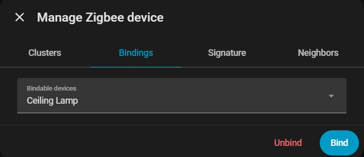
To create a direct binding to the Ceiling Lamp, just like in the local version, open ZHA -> Devices -> "Poti Controller" -> More Options -> Manage Zigbee Device -> Bindings -> "Ceiling Lamp" -> Bind.
Once that binding is created, both devices continue to communicate directly with each other. This keeps the controller and the lamp linked even though both are now part of the larger Home Assistant Zigbee network.
Using the Endpoints
Because the Home Assistant version adds three extra endpoints, the input device can now be used for more than only direct lamp control. In Home Assistant, three separate entities appear for Hue, Brightness, and the Button.
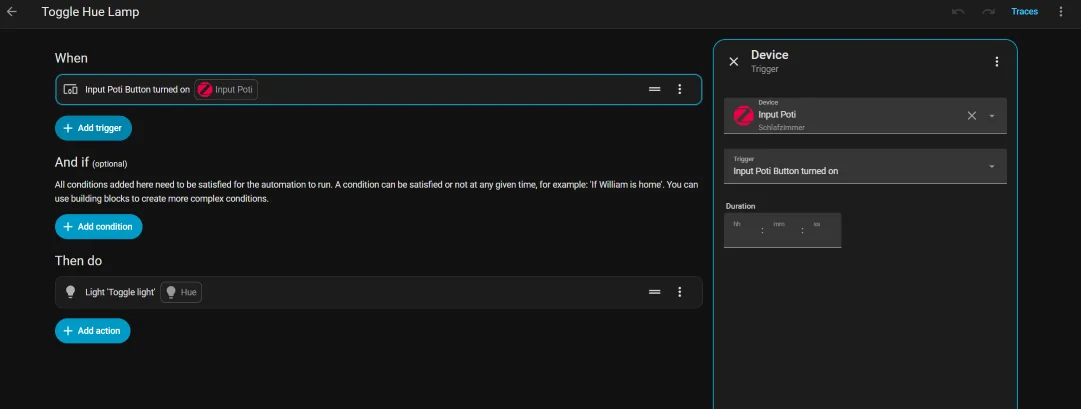
This means you can, for example, create a Home Assistant automation through Settings -> Automations & Scenes -> + Create Automation and use the input button to toggle another lamp. In the same way, the percentage-based controls can also be reused elsewhere.
And that is not limited to lighting. The controller logic can be forwarded into many other Home Assistant actions, so the same input hardware can become part of a much broader automation system.
Easteregg
As a fitting extra for the Easter weekend, there is also a more unusual communication experiment: a Morse-code connection between an ESP32-S3 and an ESP32-C6. Instead of using a typical bus or radio protocol, one board listens for serial input, translates the incoming text into Morse code, and outputs that information as timed light pulses.
The second board observes those light impulses, decodes them back into text, and then presents the recovered message on an I2C display. This creates a playful but fully functional communication chain that turns a simple optical signal into a readable message again on the receiving side.
Both boards agree on a single base unit — DOT_MS = 100 ms — from which every other duration is derived. A dot is one unit on, a dash three, a symbol gap one off, a letter gap three off, and a word gap seven off. This 1 : 3 : 7 ratio is exactly the ITU Morse standard, meaning the system is fully compatible with any compliant decoder.
On the receiver side, the ESP32-C6 does not simply detect light on and light off. It runs a three-state machine, ST_IDLE → ST_PULSE → ST_GAP, that measures how long each state lasts and classifies the result against calibrated thresholds. An important early bug taught a real lesson: the original LETTER_THR was set to 500 ms and WORD_THR to 1200 ms, which was far too generous and caused multiple letters to collapse into one. Reducing those values to 200 ms and 500 ms fixed the issue immediately.
To guard against electrical noise, any pulse shorter than 25 ms is discarded, and the ADC is oversampled eight times per reading and averaged, which produces a much more stable light level than a single raw reading. The reset mechanism is deliberately non-standard: six consecutive 600 ms pulses, much longer than any valid dash, signal that the buffer should be cleared, so a corrupted transmission can always be aborted cleanly without power-cycling either board. Finally, the ? command can query the LDR's current ADC value, its recorded minimum and maximum, and even suggest an optimal threshold automatically when the spread is wide enough, making calibration much easier when ambient lighting changes.
Show Code
/*
 * ╔══════════════════════════════════════════════════════╗
 * ║   Morse Receiver — ESP32-C6  (U8g2)  v4              ║
 * ║   Fixes: Timing Thresholds + Display X-Offset         ║
 * ╠══════════════════════════════════════════════════════╣
 * ║  Library: Arduino Library Manager → "U8g2"            ║
 * ║  OLED: VCC→3.3V  GND→GND  SDA→GPIO6  SCL→GPIO7       ║
 * ║  LDR:  3.3V──[LDR]──┬──[10kΩ]──GND  │  GPIO2         ║
 * ║  Commands: '?' LDR value  'd' Debug  'r' Reset         ║
 * ╚══════════════════════════════════════════════════════╝
 */


#include <Arduino.h>
#include <Wire.h>
#include <U8g2lib.h>


// ── Pins ─────────────────────────────────────────────────
#define OLED_SCL   7
#define OLED_SDA   6
#define LDR_PIN    2


// ── U8g2 Display ─────────────────────────────────────────
U8G2_SSD1306_128X64_NONAME_F_HW_I2C u8g2(
  U8G2_R0, U8X8_PIN_NONE, OLED_SCL, OLED_SDA
);
// Alternative SH1106:
// U8G2_SH1106_128X64_NONAME_F_HW_I2C u8g2(U8G2_R0, U8X8_PIN_NONE, OLED_SCL, OLED_SDA);


// ── Display Layout ───────────────────────────────────────
#define X_OFF      3     // ← Horizontal offset in pixels (was 3px too far left)
#define FONT_W     6     // Character width for u8g2_font_6x10_tf
#define DISP_COLS  20    // (128 - X_OFF) / FONT_W = 125/6 ≈ 20 chars/line
#define DISP_ROWS   4


// ── Morse Timing ─────────────────────────────────────────
// Sender timings (DOT_MS = 100ms):
//   Dot          = 100ms ON
//   Dash         = 300ms ON
//   Symbol gap   = 100ms OFF  (within a letter)
//   Letter gap   = 300ms OFF
//   Word gap     = 700ms OFF
//
// Receiver thresholds (midpoint between levels):
//   Symbol   vs. Letter:  midpoint 100 ↔ 300  → 200ms
//   Letter   vs. Word:    midpoint 300 ↔ 700  → 500ms
//
#define DOT_MS        100


#define DASH_THR     (DOT_MS * 2)    //  200ms: boundary dot ↔ dash
#define RESET_THR    (DOT_MS * 45/10)//  450ms: boundary dash ↔ reset pulse
#define NOISE_THR    (DOT_MS / 4)    //   25ms: anything shorter = noise


// ▼▼▼ This was the bug — both values were far too large ▼▼▼
#define LETTER_THR   (DOT_MS * 2)    //  200ms pause → letter complete  (was 500ms!)
#define WORD_THR     (DOT_MS * 5)    //  500ms pause → word complete    (was 1200ms!)
// ▲▲▲


#define RESET_COUNT   6


// ── LDR ──────────────────────────────────────────────────
#define LIGHT_THR   1400    // ← value determined by test
#define ADC_SAMPLES    8


// ── State Machine ────────────────────────────────────────
enum RecvState { ST_IDLE, ST_PULSE, ST_GAP };
RecvState     state      = ST_IDLE;
unsigned long stateStart = 0;


// ── Buffers ──────────────────────────────────────────────
String morseBuffer = "";
String textBuffer  = "";
int    resetCount  = 0;
bool   dispDirty   = true;
bool   debugMode   = false;
int    lastADC     = 0;
int    ldrMin      = 4095, ldrMax = 0;


// ── Morse Tables ─────────────────────────────────────────
const char* MORSE_ALPHA[26] = {
  ".-","-...","-.-.","-..",".","..-.",
  "--.","....","..",".---","-.-",".-..","--",
  "-.","---",".--.","--.-",".-.","...","-",
  "..-","...-",".--","-..-","-.--","--.."
};
const char* MORSE_NUM[10] = {
  "-----",".----","..---","...--","....-",
  ".....","-....","--...","---..","----."
};


// ═════════════════════════════════════════════════════════
bool readLight() {
  long s = 0;
  for (int i = 0; i < ADC_SAMPLES; i++) s += analogRead(LDR_PIN);
  lastADC = (int)(s / ADC_SAMPLES);
  if (lastADC < ldrMin) ldrMin = lastADC;
  if (lastADC > ldrMax) ldrMax = lastADC;
  return lastADC > LIGHT_THR;
}


char decodeMorse(const String& m) {
  for (int i = 0; i < 26; i++) if (m == MORSE_ALPHA[i]) return 'A' + i;
  for (int i = 0; i < 10; i++) if (m == MORSE_NUM[i])   return '0' + i;
  return '?';
}


void flushLetter() {
  if (!morseBuffer.length()) return;
  char c = decodeMorse(morseBuffer);
  Serial.printf("  [%s] → '%c'\n", morseBuffer.c_str(), c);
  textBuffer += c;
  morseBuffer = "";
  dispDirty   = true;
}


void flushWord() {
  flushLetter();
  if (textBuffer.length() && textBuffer[textBuffer.length()-1] != ' ') {
    textBuffer += ' ';
    dispDirty   = true;
  }
}


void clearAll() {
  morseBuffer = ""; textBuffer = ""; resetCount = 0;
  ldrMin = 4095; ldrMax = 0; dispDirty = true;
}


// ═════════════════════════════════════════════════════════
// Display
// ═════════════════════════════════════════════════════════
void drawDisplay() {
  if (!dispDirty) return;
  dispDirty = false;


  // Visible text: last DISP_ROWS × DISP_COLS characters
  String vis = textBuffer.substring(
    max(0, (int)textBuffer.length() - DISP_ROWS * DISP_COLS));


  u8g2.clearBuffer();
  u8g2.setFont(u8g2_font_6x10_tf);


  // ── Header line ───────────────────────────────────────
  u8g2.setCursor(X_OFF, 8);
  u8g2.print("MORSE RX");


  // Current morse buffer (right-aligned, no X_OFF correction needed)
  String mb = morseBuffer.length() > 8
    ? "~" + morseBuffer.substring(morseBuffer.length() - 7) : morseBuffer;
  if (mb.length()) {
    u8g2.setCursor(128 - (int)mb.length() * FONT_W, 8);
    u8g2.print(mb);
  }
  u8g2.drawHLine(0, 10, 128);


  // ── Text lines ────────────────────────────────────────
  const int lineY[4] = {22, 34, 46, 58};
  for (int r = 0; r < DISP_ROWS; r++) {
    int s = r * DISP_COLS;
    if (s >= (int)vis.length()) break;
    u8g2.setCursor(X_OFF, lineY[r]);
    u8g2.print(vis.substring(s, min(s + DISP_COLS, (int)vis.length())));
  }


  // ── Debug Overlay ─────────────────────────────────────
  if (debugMode) {
    u8g2.drawHLine(0, 54, 128);
    u8g2.setFont(u8g2_font_5x7_tf);
    char dbg[22];
    snprintf(dbg, sizeof(dbg), " %-3s ADC:%-4d T:%-4d",
             lastADC > LIGHT_THR ? "ON" : "OFF", lastADC, LIGHT_THR);
    u8g2.setCursor(0, 63);
    u8g2.print(dbg);
  }


  u8g2.sendBuffer();
}


void showBigMessage(const char* l1, const char* l2 = "") {
  u8g2.clearBuffer();
  u8g2.setFont(u8g2_font_9x15_tf);
  u8g2.setCursor(X_OFF, 22); u8g2.print(l1);
  u8g2.setFont(u8g2_font_6x10_tf);
  u8g2.setCursor(X_OFF, 42); u8g2.print(l2);
  u8g2.sendBuffer();
  dispDirty = true;
}


// ═════════════════════════════════════════════════════════
void setup() {
  Serial.begin(115200);
  delay(600);
  Serial.println("\n╔════════════════════════════════════╗");
  Serial.println("║  ESP32-C6 Morse Receiver (U8g2 v4)  ║");
  Serial.println("╠════════════════════════════════════╣");
  Serial.printf( "║  LETTER_THR=%dms  WORD_THR=%dms     ║\n",
                 LETTER_THR, WORD_THR);
  Serial.printf( "║  LIGHT_THR=%d  X_OFF=%dpx           ║\n",
                 LIGHT_THR, X_OFF);
  Serial.println("╚════════════════════════════════════╝\n");


  u8g2.begin();


  u8g2.clearBuffer();
  u8g2.setFont(u8g2_font_6x10_tf);
  u8g2.setCursor(X_OFF, 10); u8g2.print("Morse Receiver");
  u8g2.setCursor(X_OFF, 24); u8g2.print("U8g2 v4  OK");
  u8g2.setCursor(X_OFF, 38); u8g2.print("LDR Thr: "); u8g2.print(LIGHT_THR);
  u8g2.setCursor(X_OFF, 50); u8g2.print("Letter: "); u8g2.print(LETTER_THR); u8g2.print("ms");
  u8g2.setCursor(X_OFF, 62); u8g2.print("Word:   "); u8g2.print(WORD_THR); u8g2.print("ms");
  u8g2.sendBuffer();
  delay(2500);


  pinMode(LDR_PIN, INPUT);
  Serial.println("Commands: '?' LDR  |  'd' Debug  |  'r' Reset\n");


  dispDirty = true;
  stateStart = millis();
  drawDisplay();
}


// ═════════════════════════════════════════════════════════
void loop() {
  if (Serial.available()) {
    char cmd = Serial.read();
    if (cmd == '?') {
      long s = 0;
      for (int i = 0; i < 20; i++) { s += analogRead(LDR_PIN); delay(5); }
      int v = (int)(s/20);
      Serial.printf("[LDR] Now=%d Min=%d Max=%d Thr=%d LED:%s\n",
                    v, ldrMin, ldrMax, LIGHT_THR,
                    v > LIGHT_THR ? "ON" : "OFF");
      if (ldrMax > ldrMin+200)
        Serial.printf("  → Recommended threshold: %d\n", (ldrMin+ldrMax)/2);
    }
    if (cmd == 'd') {
      debugMode=!debugMode; dispDirty=true; drawDisplay();
      Serial.printf("[Debug] %s\n", debugMode?"ON":"OFF");
    }
    if (cmd == 'r') {
      clearAll(); drawDisplay(); Serial.println("[Reset]");
    }
  }


  bool ledOn = readLight();
  unsigned long now  = millis();
  unsigned long elap = now - stateStart;


  switch (state) {


    case ST_IDLE:
    case ST_GAP:
      if (ledOn) {
        // New pulse → evaluate pause first
        if (state == ST_GAP) {
          if      (elap >= WORD_THR)   { Serial.println("[WORD]");   flushWord();   }
          else if (elap >= LETTER_THR) { Serial.println("[LETTER]"); flushLetter(); }
          // elap < LETTER_THR: symbol gap, letter continues
        }
        state = ST_PULSE; stateStart = now;
        if (debugMode) { dispDirty=true; drawDisplay(); }


      } else if (state == ST_GAP && elap >= WORD_THR && morseBuffer.length()) {
        // Timeout: finalize last character/word
        Serial.println("[TIMEOUT → Word]");
        flushWord();
        state = ST_IDLE;
        drawDisplay();
      }
      break;


    case ST_PULSE:
      if (!ledOn) {
        if (elap < NOISE_THR) {
          // Ignore noise
        } else if (elap >= RESET_THR) {
          resetCount++;
          Serial.printf("[Reset pulse #%d: %lums]\n", resetCount, elap);
          if (resetCount >= RESET_COUNT) {
            showBigMessage("* RESET *", "Buffer cleared");
            delay(1800); clearAll();
            state=ST_IDLE; stateStart=now; drawDisplay(); return;
          }
          morseBuffer += "-";
        } else if (elap >= DASH_THR) {
          morseBuffer += "-"; resetCount = 0;
          Serial.printf("  — %lums  [%s]\n", elap, morseBuffer.c_str());
        } else {
          morseBuffer += "."; resetCount = 0;
          Serial.printf("  . %lums  [%s]\n", elap, morseBuffer.c_str());
        }
        dispDirty=true; drawDisplay();
        state=ST_GAP; stateStart=now;
      }
      break;
  }


  // Debug refresh every 500ms
  static unsigned long lastDbg = 0;
  if (debugMode && state!=ST_PULSE && millis()-lastDbg>500) {
    lastDbg=millis(); dispDirty=true; drawDisplay();
  }
}/*
* ╔══════════════════════════════════════════════════════╗
* ║ Morse Code Sender — ESP32-S3 ║
* ╠══════════════════════════════════════════════════════╣
* ║ Enter text via Serial → LED blinks Morse ║
* ║ "!RESET" → sends custom reset pattern ║
* ╠══════════════════════════════════════════════════════╣
* ║ Connections: ║
* ║ LED (+ 220Ω) → GPIO2 → GND ║
* ║ (or onboard LED depending on board) ║
* ╠══════════════════════════════════════════════════════╣
* ║ Reset pattern (NOT standard Morse): ║
* ║ 6 × extra-long pulse (600 ms) with 50 ms gaps ║
* ╚══════════════════════════════════════════════════════╝
*/
// ── Configuration ────────────────────────────────────────────
#define LED_PIN 2 // GPIO pin of the LED
#define DOT_MS 100 // Base unit in ms (dot duration)
// Derived timings
#define DASH_MS (DOT_MS * 3)
#define SYM_GAP_MS DOT_MS
#define LETTER_GAP_MS (DOT_MS * 3)
#define WORD_GAP_MS (DOT_MS * 7)
// Reset pattern: 6 × 600 ms (not a valid Morse character)
#define RESET_PULSE_MS (DOT_MS * 6)
#define RESET_GAP_MS (DOT_MS * 2)
#define RESET_PRE_MS (DOT_MS * 10)
#define RESET_COUNT 6
// ── Morse Tables ─────────────────────────────────────────────
const char* MORSE_ALPHA[26] = {
".-", "-...", "-.-.", "-..", ".",
"..-.", "--.", "....", "..", ".---",
"-.-", ".-..", "--", "-.", "---",
".--.", "--.-", ".-.", "...", "-",
"..-", "...-", ".--", "-..-", "-.--",
"--.."
};
const char* MORSE_NUM[10] = {
"-----", ".----", "..---", "...--", "....-",
".....", "-....", "--...", "---..", "----."
};
// ── LED Control ──────────────────────────────────────────────
inline void ledOn() { digitalWrite(LED_PIN, HIGH); }
inline void ledOff() { digitalWrite(LED_PIN, LOW); }
// ── Send Morse Symbols ───────────────────────────────────────
void sendDot() {
ledOn(); delay(DOT_MS);
ledOff(); delay(SYM_GAP_MS);
}
void sendDash() {
ledOn(); delay(DASH_MS);
ledOff(); delay(SYM_GAP_MS);
}
// Send a complete Morse code string (e.g. ".-")
void sendMorseCode(const char* code) {
for (int i = 0; code[i] != '\0'; i++) {
if (code[i] == '.') sendDot();
else if (code[i] == '-') sendDash();
}
// Letter gap = 3 units total; 1 already counted by last SYM_GAP
delay(LETTER_GAP_MS - SYM_GAP_MS);
}
// Send a single character as Morse
void sendChar(char c) {
c = toupper(c);
if (c >= 'A' && c <= 'Z') {
Serial.printf(" %c → %s\n", c, MORSE_ALPHA[c - 'A']);
sendMorseCode(MORSE_ALPHA[c - 'A']);
} else if (c >= '0' && c <= '9') {
Serial.printf(" %c → %s\n", c, MORSE_NUM[c - '0']);
sendMorseCode(MORSE_NUM[c - '0']);
} else if (c == ' ') {
// Word gap: 7 units − 3 already from letter gap
delay(WORD_GAP_MS - LETTER_GAP_MS);
Serial.println(" [SPACE]");
} else {
Serial.printf(" '%c' skipped (not a Morse character)\n", c);
}
}
// Send a complete text string as Morse
void sendText(const String& text) {
Serial.printf("\nSending: \"%s\"\n", text.c_str());
Serial.println("Morse output:");
for (int i = 0; i < (int)text.length(); i++) {
sendChar(text.charAt(i));
}
Serial.println("\n[Done — Ready for next input]\n");
}
// ── Send Reset Signal ────────────────────────────────────────
// Non-standard: 6 extra-long pulses (600 ms) with 200 ms gaps each
// Preceded and followed by 1000 ms silence
void sendResetSignal() {
Serial.println("\n>>> Sending RESET signal <<<");
Serial.printf("Pattern: %d × %d ms ON / %d ms OFF\n",
RESET_COUNT, RESET_PULSE_MS, RESET_GAP_MS);
ledOff();
delay(RESET_PRE_MS); // Long silence → receiver detects transmission pause
for (int i = 0; i < RESET_COUNT; i++) {
ledOn();
delay(RESET_PULSE_MS);
ledOff();
delay(RESET_GAP_MS);
Serial.printf(" Pulse %d / %d ✓\n", i + 1, RESET_COUNT);
}
delay(RESET_PRE_MS); // Long silence after reset
Serial.println(">>> RESET signal sent <<<\n");
}
// ── Setup & Loop ─────────────────────────────────────────────
void setup() {
Serial.begin(115200);
pinMode(LED_PIN, OUTPUT);
ledOff();
delay(800);
Serial.println();
Serial.println("╔══════════════════════════════════╗");
Serial.println("║ ESP32-S3 Morse Sender ║");
Serial.println("╠══════════════════════════════════╣");
Serial.printf( "║ DOT=%dms DASH=%dms LED=GPIO%d ║\n",
DOT_MS, DASH_MS, LED_PIN);
Serial.println("╚══════════════════════════════════╝");
Serial.println("Input → Enter | '!RESET' = Reset pattern\n");
}
void loop() {
if (Serial.available() > 0) {
String input = Serial.readStringUntil('\n');
input.trim();
if (input.length() == 0) return;
if (input.equals("!RESET")) {
sendResetSignal();
} else {
sendText(input);
}
}
}More about ADC behavior and analog readings can be found on our Week 9 Input Devices group page.

