Week 9: Input Devices
Group Assignment
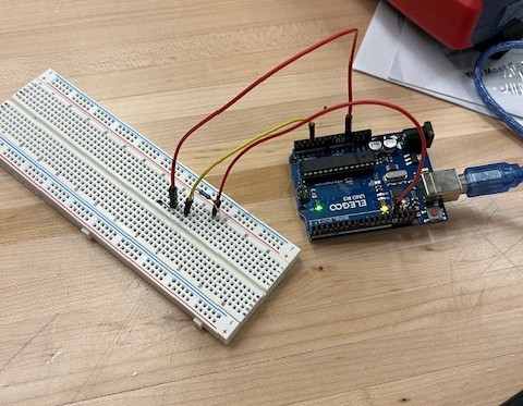
As a group, we tested a thermistor and a photoresistor in simple circuits. We started with the thermistor. As the temperature of the thermistor increases, the resistance decreases. As you might imagine, when the temperature decreases, the resistance increases. Using the below code, we could read a number between 0 to 1024, with 0 reading a voltage of 0 and 1024 reading the full VCC voltage. It was a simple circuit with just an Arduino Uno, a resistor, and a thermistor. We tested different temperatures by putting the thermistor against our fingers and against a tub of ice cream.
For the photoresistor we used the same circuit and just switched out the thermistor for the photoresistor. More light will cause less resistance and less light will cause more resistance. We used the same code as the thermistor. We tested this by turning the lights off and on in the room and cupping our hands over the photoresistor. For both of these, you would have to do some calculations to get meaningful data from it. Both of these used an analog pin on the Arduino Uno to get input.
        void setup() {
          pinMode(4, INPUT);
          Serial.begin(9600);
        }

        void loop() {
          int sensorValue;
          sensorValue = analogRead(4);
          Serial.println(sensorValue);
          delay(100);
        }
Using an Analog Joystick
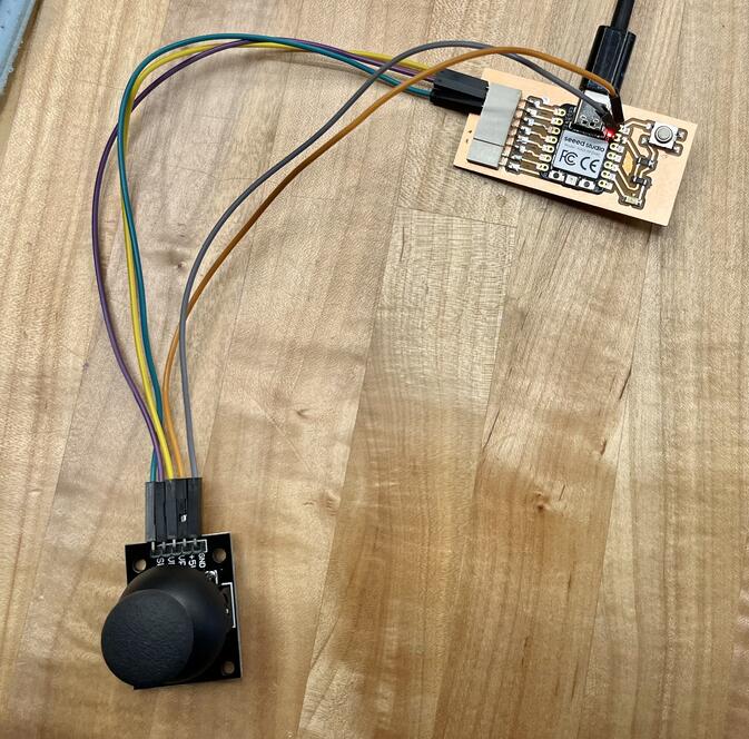
For this week, I decided to try using a joystick. I used the board I made in
week 8 to do this. I hooked up the x and y pins on the joystick to pins 0 and 1 respectively. I connected the button pin to pin 2. I did not have anywhere to plug in pins to go into 5V and ground so I just rested the wires on the appropriate pins on the Xiao microcontroller. If I were to make this a proper board or make another development board, I would make it easier to use the 5V and ground pins.
The code for this prints on screen which way the joystick is pointing and if the joystick’s button has been pressed. The position can be found by reading in the x and y coordinates from the analog pins.
I used this page on Wokwi to learn how to translate the numbers into directions as well as reading in the input correctly. I created the logic in the loop function. You can see an example of the code and circuit working in the above video.
        // Define the pins for the joystick
        const int X_PIN = D0;  // X-axis connected to analog pin A0
        const int Y_PIN = D1;  // Y-axis connected to analog pin A1
        const int BUTTON_PIN = D2;  // Button connected to digital pin 2

        void setup() {
          Serial.begin(9600);
          pinMode(BUTTON_PIN, INPUT_PULLUP);
          Serial.println("Joystick Test Initialized");
        }

        void loop() {
          int xValue = analogRead(X_PIN); // Read the X-axis value
          int yValue = analogRead(Y_PIN); // Read the Y-axis value
          bool buttonPressed = !digitalRead(BUTTON_PIN); // Check if the button is pressed

          // Determine joystick direction
          String direction = "";

          //Center
          if(xValue >= 100 && xValue <= 923 && yValue >= 100 && yValue <= 923){
            direction = "Center";
          }
          else{
            //up
            if(yValue > 923){
              direction = "Top ";
            }
            //down
            else if(yValue < 100){
              direction = "Bottom ";
            }

            //left
            if(xValue > 923){
              direction += "Left";
            }
            //right
            else if(xValue < 100){
              direction += "Right";
            }
          }

          // Print joystick status
          Serial.print("Direction: ");
          Serial.println(direction);

          // Check button press
          if (buttonPressed) {
            Serial.println("Button Pressed!!!");
          }

          delay(200);
        }