Kaz's Final Project
This is where I will define my final project idea and start the documentation process. I decided I wanted to try and make a series of electromagnetic that can be attached to a shield that could be used to trap metal armaments against the shield.
Video
Research
I had to learn about transistors, as they would be incredibly important to the completion of my project. A transistor is a semiconductor device used to amplify or switch electronic signals and electrical power. It typically has three terminals: the base, collector, and emitter. By applying a small current or voltage to the base, a transistor can control a much larger current flowing between the collector and emitter, making it a fundamental building block in modern electronics. The specific kind of transistor I used in my project is a MOSFET, or Metal-Oxide-Semiconductor Field-Effect Transistor. A MOSFET is a type of field-effect transistor (FET) that uses an electric field to control the flow of current. It has three terminals: gate, drain, and source. There are also two types of MOSFETs: n-channel and p-channel, which refer to the type of charge carriers that flow through the device. In an n-channel MOSFET, electrons are the majority carriers, while in a p-channel MOSFET, holes are the majority carriers. The gate terminal is insulated from the channel by a thin layer of oxide, allowing for high input impedance and low power consumption. When a voltage is applied to the gate, it creates an electric field that modulates the conductivity of the channel between the drain and source terminals, enabling or disabling current flow. MOSFETs are widely used in digital and analog circuits for switching and amplification due to their efficiency and fast switching speeds.
Past Fab Academy Projects
THere have been a few other projects using electromagnets for Fab Academy, but I am the first one to use electromagnets to entrap items, whereas most other projects used them to move or secure moving components of their projects.
Modeling
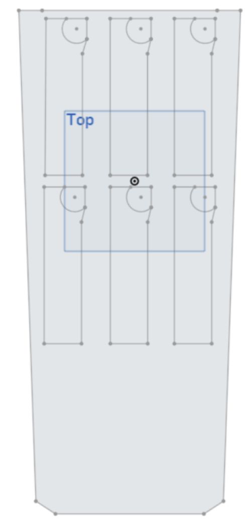
This is my initial design for what I wanted to do as a project, an electromagnet that could be attached to a glove, which could then be used to pick up small metal objects. However, I realized that was boring, so I decided to make a shield instead. Here is an Onshape drawing of what my project might end up looking like. You can find a link to my Onshape file here.
PCB Design
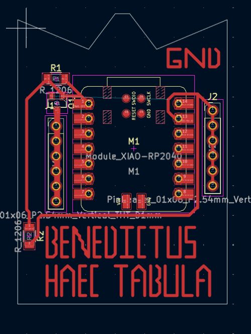
In Week 15, I designed a beginning board that I might end up using for my project. However, I ended up not using this board because it lacked the necessary components that my project would require. This board uses a transistor to send a signal to the electromagnets through the source side of the transistor. However, the keen eye may notice that the drain side of the transistor is not connected to anything, which means that the board is non functional. In fact, I don't ever recall even milling this board, and I'm not sure why its here.
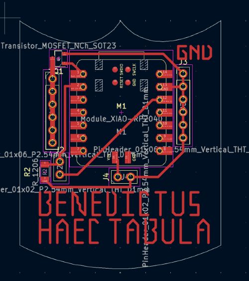
Following the incomplete board, I designed this board, which I is much closer to what I will need for my final project.
The transistor is now connected, with the thick trace on the left side of the board connecting to the source side of the transistor, and the drain connecting to the right side of the board with those traces.
However, this board is also incomplete, as the connections are incorrect, albeit complete. The source is supposed to connect to ground, and the drain connects to the electromagnets.
On this board, it is reversed.
Additionally, there is no place for the 12 volt connection to the electromagnets, which is a major oversight.
However, this board does have a place for the toggleable button to connect, which can be found on the lower left side of the board.
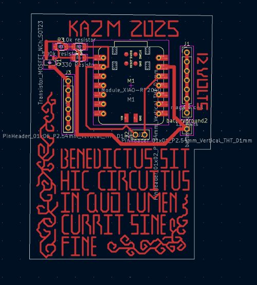
Finally, after multiple re designs, I ended up with a board that looked like this. This is the board I used in my final project, and it worked perfectly. The transistor is connected properly, and runs through the correct amount of resistors with the right resistance, as well as a pulldown resistor from the gate of the transistor to the pin D0 on the XIAO RP2040, with the source connected to ground and the drain connected to the electromagnets. The through holes for the toggleable button are wired properly with the right resistor and the 12 volt connection is also wired properly. I also added labels for mostly everything on the board, which is a good practice to have. There is also a through hole for the battery's connection, an oversight that my last boards did not have. You can find it on the lower right side of the board. The latin blessing on it is much more complex and translates to "Blessed be this board in which light flows without end". I also added fancy filigrees on the sides of the board to jazz it up.
Code
This code was incredibly simple. All it does is wait for a signal from the toggleable button, then sends a signal through the gate of the transistor which then powers the magnets on. When the button is no longer sending a signal, the transistor stops sending a signal to the electromagnets, which then turn off. You can find the arduino file here.
const int solenoidPin = D0;   // Connected to the MOSFET gate
const int buttonPin = D1;     // Connected to button input

void setup() {
  pinMode(solenoidPin, OUTPUT);
  pinMode(buttonPin, INPUT);  // External pulldown handles logic level

  digitalWrite(solenoidPin, LOW);  // Start solenoid OFF
}

void loop() {
  int buttonState = digitalRead(buttonPin);

  if (buttonState == HIGH) {
    digitalWrite(solenoidPin, HIGH);  // Button pressed → solenoid ON
  } else {
    digitalWrite(solenoidPin, LOW);   // Button released → solenoid OFF
  }
}
Physical Components and Assembly
I started by CNC'ing out a piece of birch ply wood and laid the magnets in the slots. You can find the DXF file (and all other relevant onshape files) here.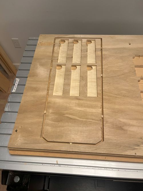
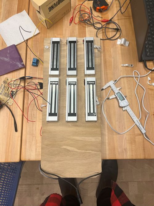
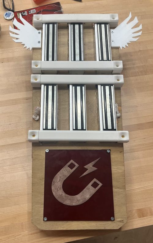
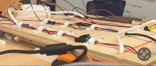
After that, I 3d printed brackets and used them to hold the magnets in place. I also attached an acrylic ensignia of a magnet to fill up the empty space on the bottom of the shield.
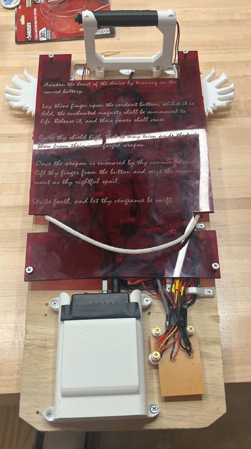
Then I got to work on the back side of the board. I 3d printed wire brackets, a battery casing, and an acrylic backboard with instructions on how to use the shield, and assembled it all together.

Materials
Here is the link to the list of materials I had to order.
Here is a full list of everything that was used to create this project
- 1x PCB Board
- 1x 3D Printed Battery Holder
- 18x 3D Printed Wire Brackets
- 1x CNC'd Birch Plywood Backboard
- 1x Laser Cut Acrylic Cover
- 1x Laser Cut Acrylic Ensignia
- 6x Electromagnets
- 1x MOSFET Transistors
- 2x 10k Resistors
- 1x 330 Resistor
- 1x XIAO Seeed RP2040
- 1x Battery Pack
- 4x 3D Printed Electromagnet Brackets
- 1x Toggleable Button
CC License