This week I worked on things for my final project.
New Board
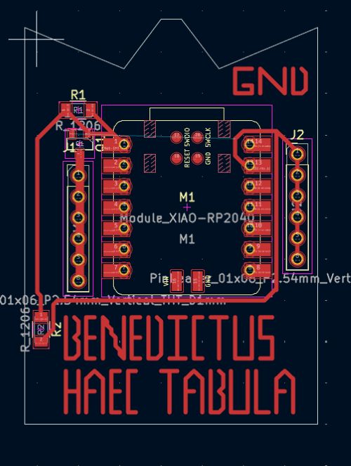
I created a circuit board design which I intended to use in my final project, which you can see here. You can find the KiCad PCB files here and the schematic files here. Noteably, this board uses throughhole pin headers, which required me to create three seperate .rml files, one for the traces, one for the holes, and one for the edge cuts. You may also notice that there is writing on this board, "BENEDICTUS HAEC TABULA". This is a latin blessing that translates to "blessed be this board", which I am praying works because I think it would be really funny if this board worked perfectly for my final project and I didn't have to make another one.
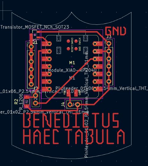
However, I was unlucky, as I realized this board would not satisfy the requirements for my final project. So much for the blessing, I guess. I ended up creating a new board, which you can see here. This board has a few more features, such as the ability to use buttons to turn the electromagnets on and off. You can find the KiCad PCB files here and the schematic files here.
As of now, I have not yet soldered this board, as I am waiting for the MOSFETs to arrive. However, I will update this page with the soldered board once they arrive. I am also waiting for the electromagnets to arrive, which I will be using in my final project. I will also update this page with the electromagnets once they arrive.
Transistors
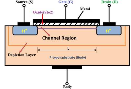
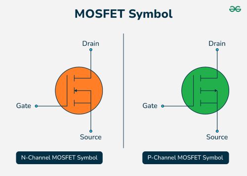
This week I also had to learn about transistors, as they would be incredibly important to the completion of my project. A transistor is a semiconductor device used to amplify or switch electronic signals and electrical power. It typically has three terminals: the base, collector, and emitter. By applying a small current or voltage to the base, a transistor can control a much larger current flowing between the collector and emitter, making it a fundamental building block in modern electronics. The specific kind of transistor I used in my project is a MOSFET, or Metal-Oxide-Semiconductor Field-Effect Transistor. A MOSFET is a type of field-effect transistor (FET) that uses an electric field to control the flow of current. It has three terminals: gate, drain, and source. There are also two types of MOSFETs: n-channel and p-channel, which refer to the type of charge carriers that flow through the device. In an n-channel MOSFET, electrons are the majority carriers, while in a p-channel MOSFET, holes are the majority carriers. The gate terminal is insulated from the channel by a thin layer of oxide, allowing for high input impedance and low power consumption. When a voltage is applied to the gate, it creates an electric field that modulates the conductivity of the channel between the drain and source terminals, enabling or disabling current flow. MOSFETs are widely used in digital and analog circuits for switching and amplification due to their efficiency and fast switching speeds. As of now, the MOSFETS I am using have not arrived yet, but they have been ordered and are on there way. If they arrive before 5/14, I will update this page with the soldered board.
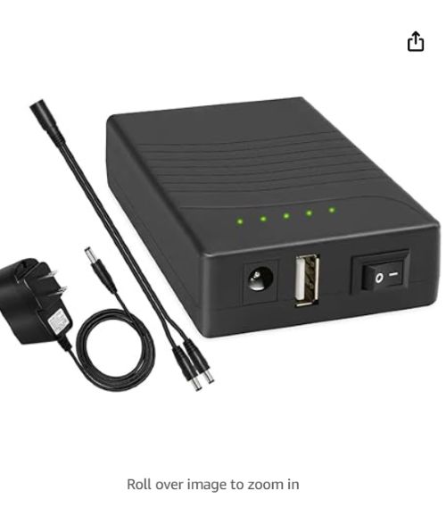
I also found a great battery that would work to power my electromagnets and my board, as it has both 12v and 5v ports, and can push this voltage out at 6A. The link to it is here.