Week 7
Computer Controlled Machining
Welcome to week 7 of FabAcademy! This assignment delves into the realm of CNC by embarking on a project to create something substantial. Through this process, we aim to grasp the capabilities of the machine and explore its potential.
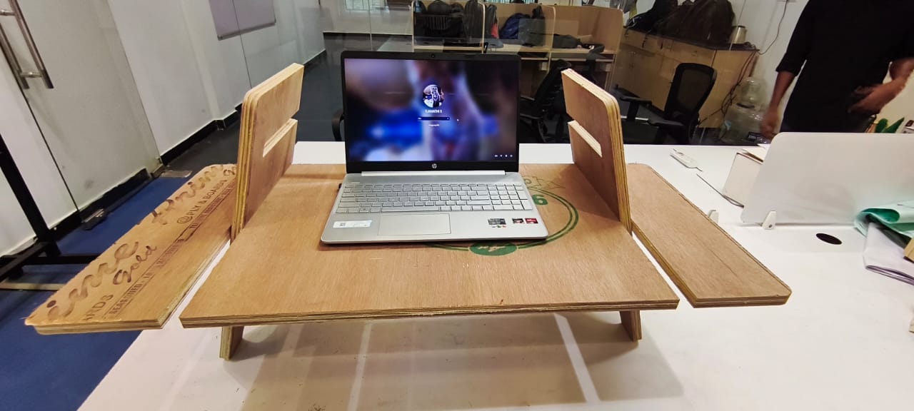
My Heroshot for this Week
 |
What is Computer Controlled Machining?
Computer numerical control (CNC) machining, a technique in manufacturing, employs computerized software and hardware to direct cutting tool movements, shaping materials into desired products. CNC machines are versatile, capable of accurately cutting, drilling, and milling various materials like wood, metal, plastics, and composites. The software facilitates the creation of intricate designs, ensuring precise replication by the machine.
CNC Milling Machine:
A CNC (Computer Numerical Control) Milling Machine is used to precisely cut, carve, or engrave wooden components based on a computer-generated design. The machine operates using pre-programmed software to perform complex tasks with high accuracy, making it ideal for producing intricate patterns, furniture components, and decorative items.
Outcomes
Group assignments:
Complete your lab's safety training
Test runout, alignment, fixturing, speeds, feeds, materials and toolpaths for your machine
Document your work to the group work page and reflect on your individual page what you learned
Individual assignments:
Make (design+mill+assemble) something big
reference links


Group Assignment :
This week's group assingment was to do the lab's safety training and to test the runout, alignment, fixturing, speeds, feeds, materials and toolpaths for the machine in our lab. We milled out a plywood test piece with various features mentioned in the group assignment.
Visit our Group assignment page here
Individual Assignment :
Design:
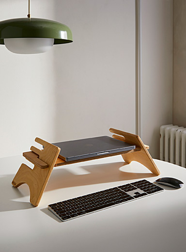
I took inspiration from a Adjustable height computer stand design by Portuguese Designer and modelled my version of it on solidworks
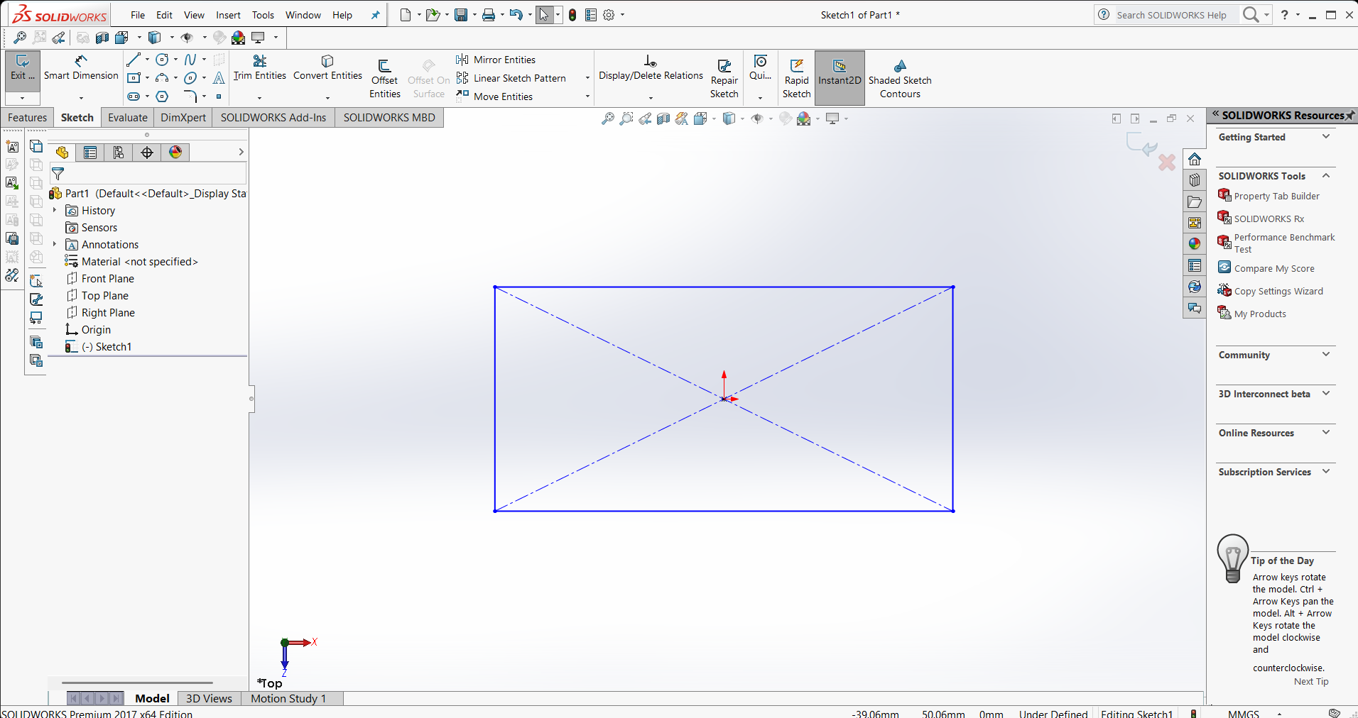
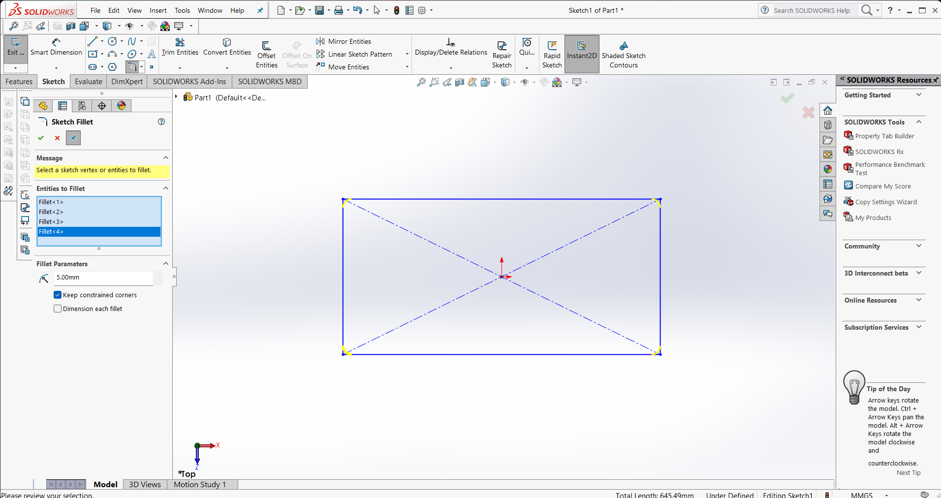
I began the design process by focusing on the dimentions.
Initially, I designed the top of the structure

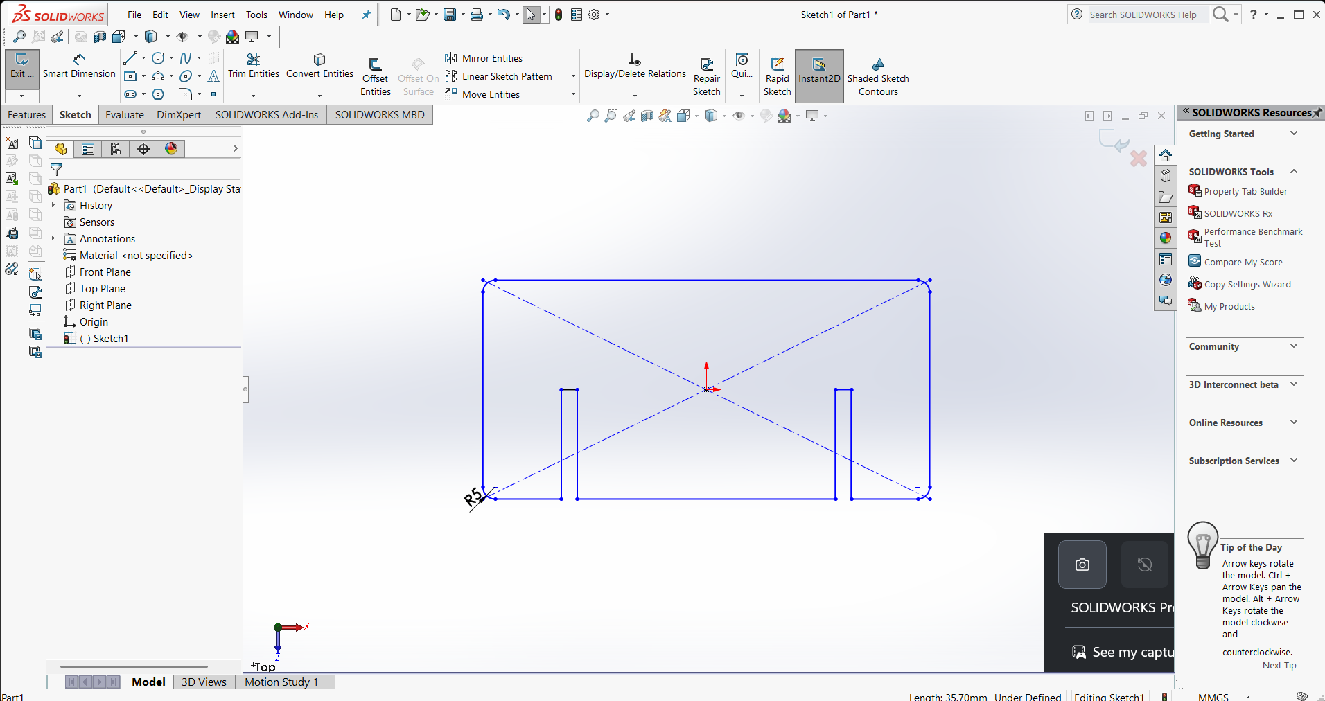
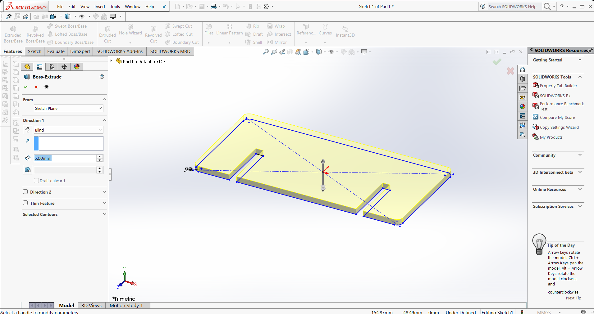
now i started to design the side legs
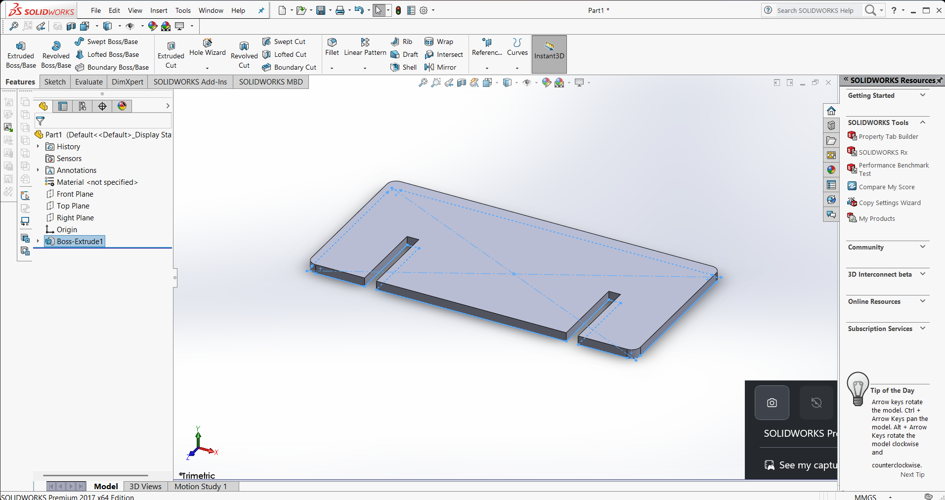
After designing the components, i have started to assemble each
After assembling, i have gotten this results
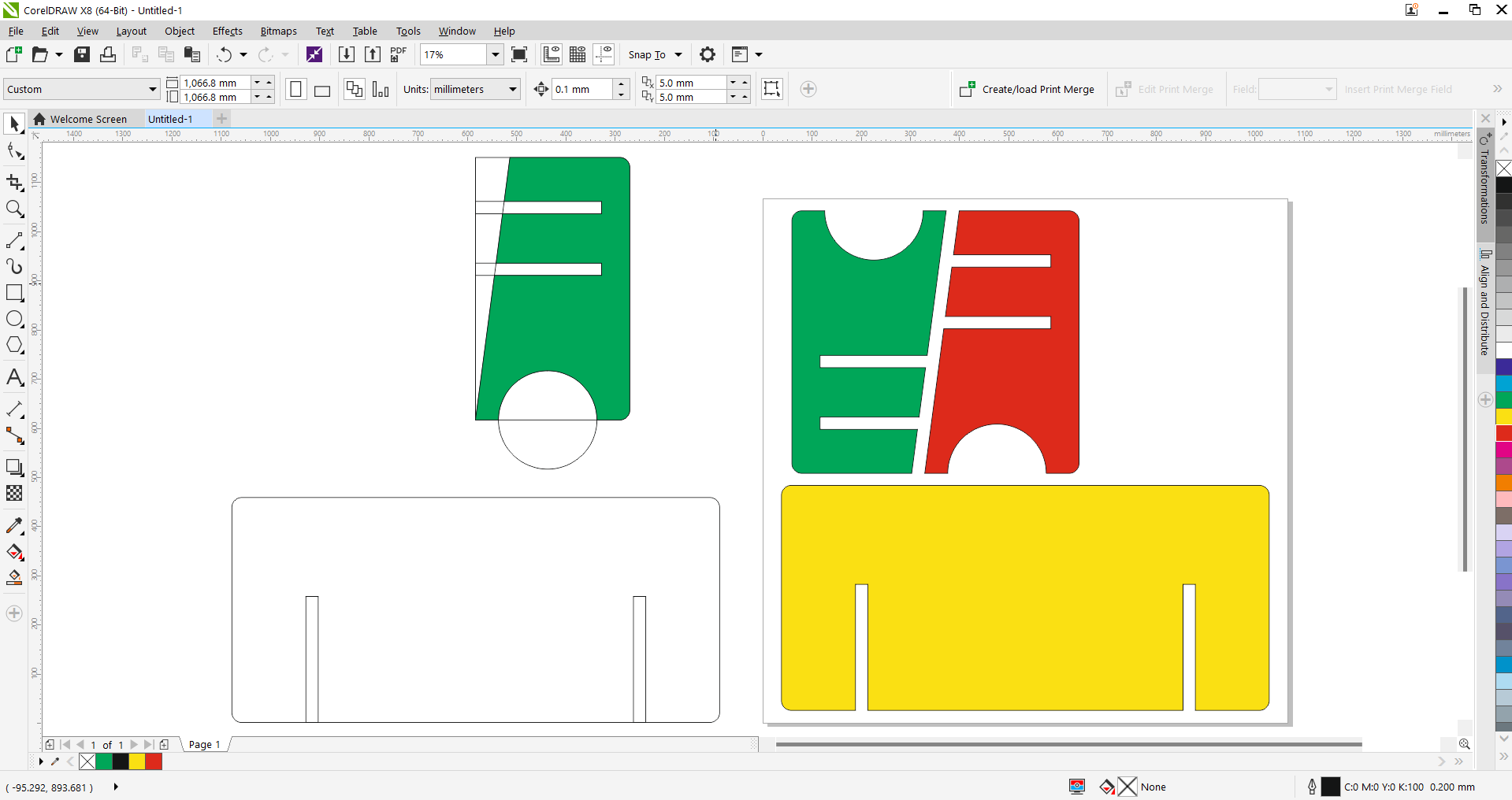
Then i imported them on coral draw to convert it into dxf file
Dog bone:
Dog bone is a woodcutting technique employed to craft precise and seamless joints between two wood pieces. This method entails carving out a small notch or groove at the end of one piece to perfectly accommodate the shape of the other, resulting in a flush and sturdy joint.
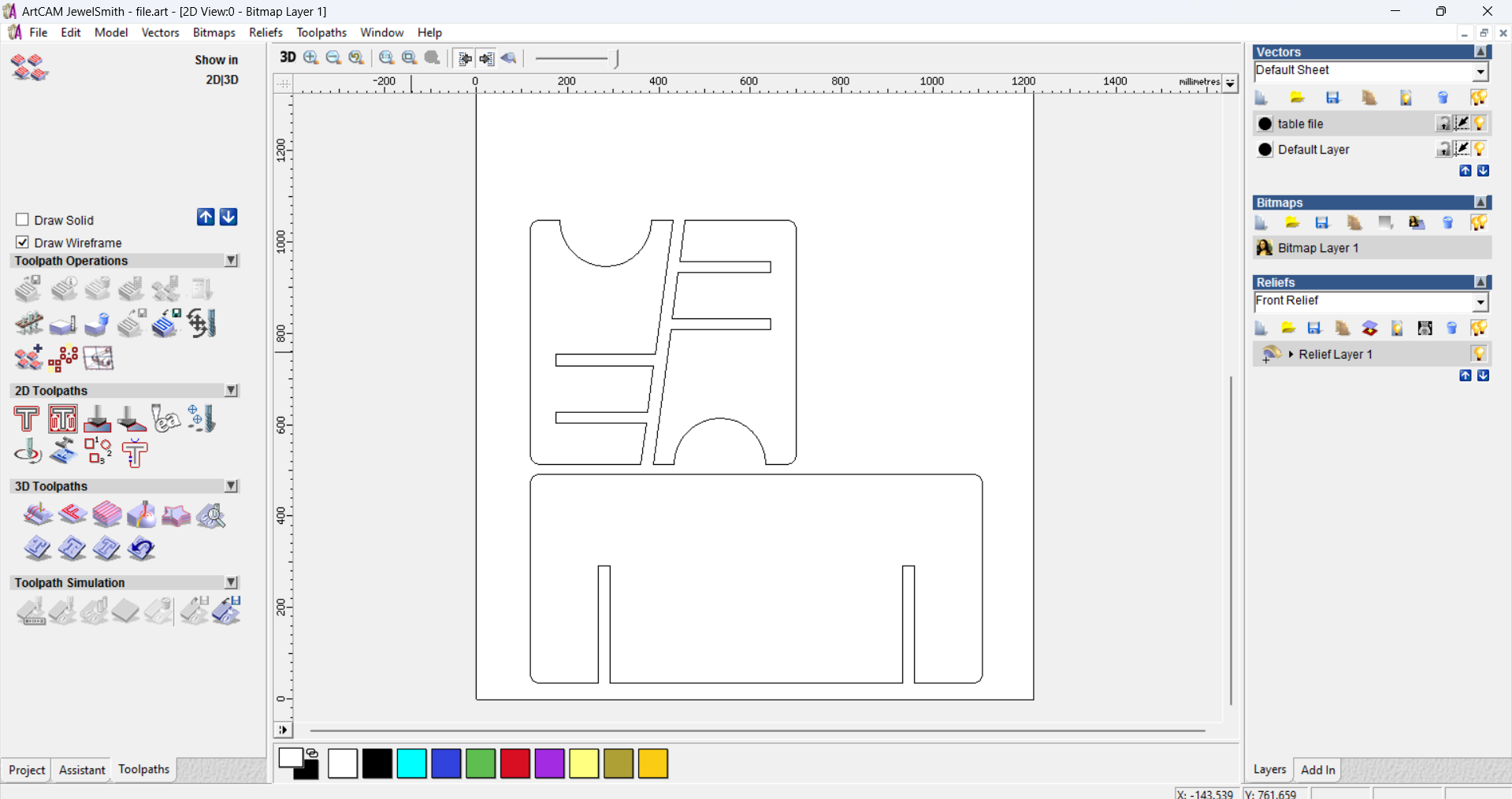
Art cam:
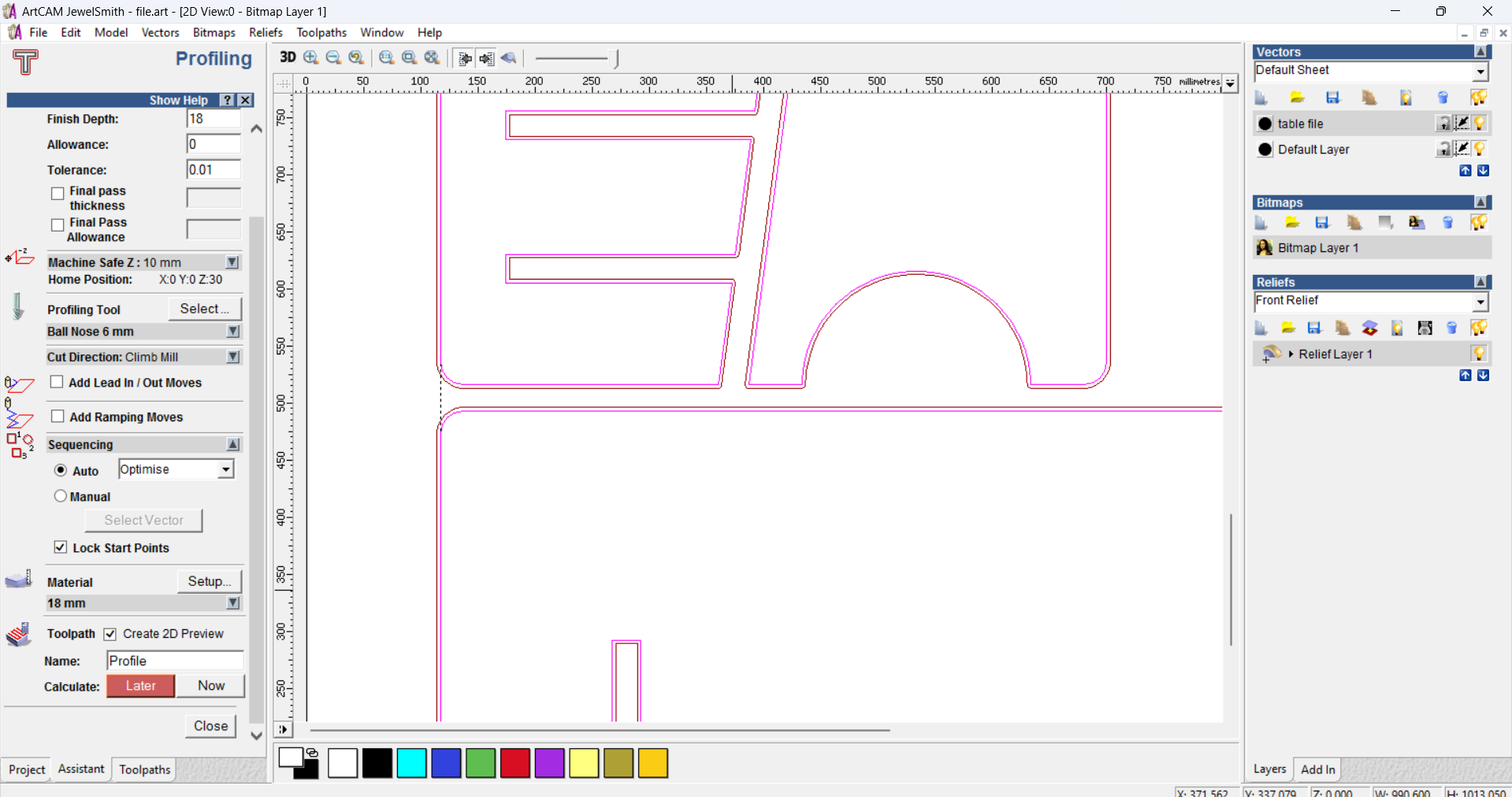
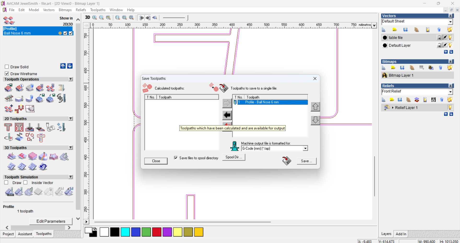
Art cam is a software application used for creating and preparing designs specifically for CNC (Computer Numerical Control) routing machines. It allows users to design intricate 2D and 3D models, generate toolpaths, and simulate the machining process. Art cam software is commonly utilized in woodworking, signage, and other industries that involve CNC routing and engraving.
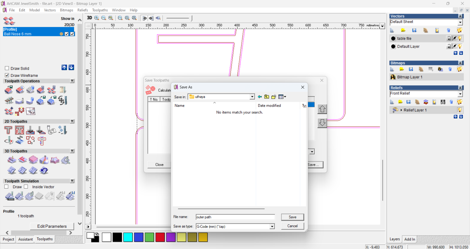
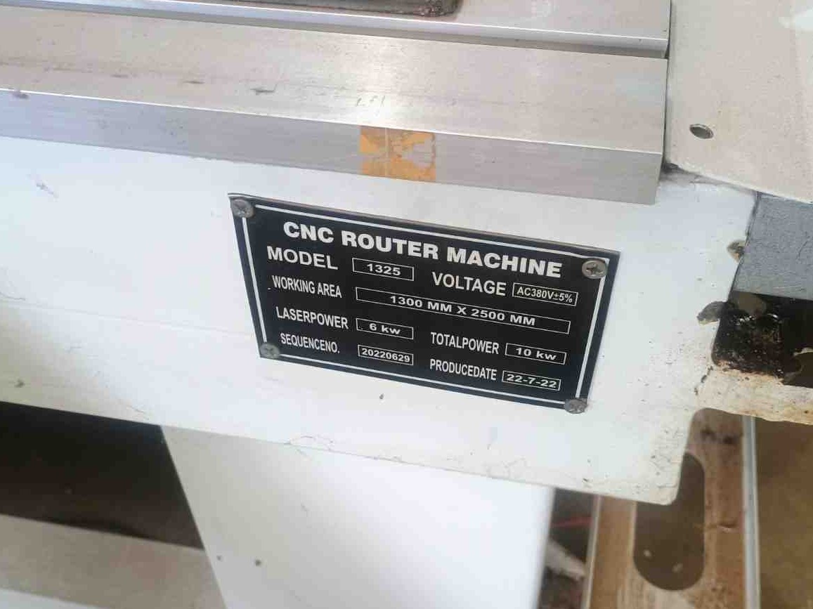
Once I had the .dxf file, I saved it onto a USB flash drive and subsequently transferred it to the PC that is connected to the CNC Wood Router STM 1325 machine.
Problems Faced and How I Overcame the Problems:
Issue with CNC Wood Router STM 1325 and Solution
Our CNC Wood Router STM 1325 CNC experienced a malfunction due to a damaged MOSFET in the Z-axis. This issue raised concerns about completing our CNC week projects on time. After discussing the problem with my instructors, they suggested using the VCarve cutter as an alternative.
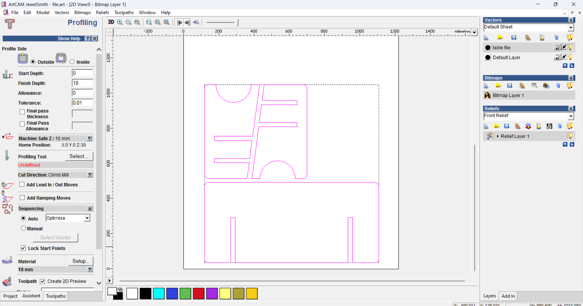
Adjustments and Solution Implementation
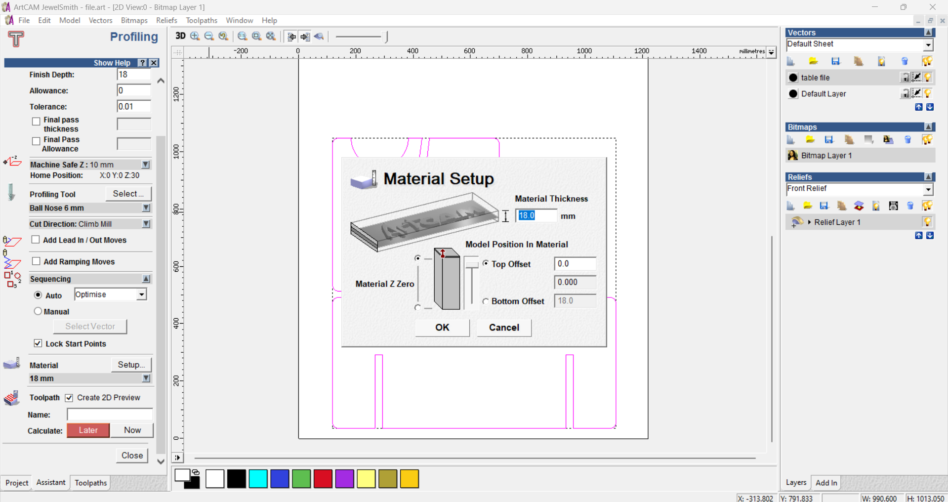
The cutter has the capability to mill plywood up to 12 mm in thickness. To accommodate this, I adjusted my design to 18 mm, which aligns with the available plywood stock in our inventory.
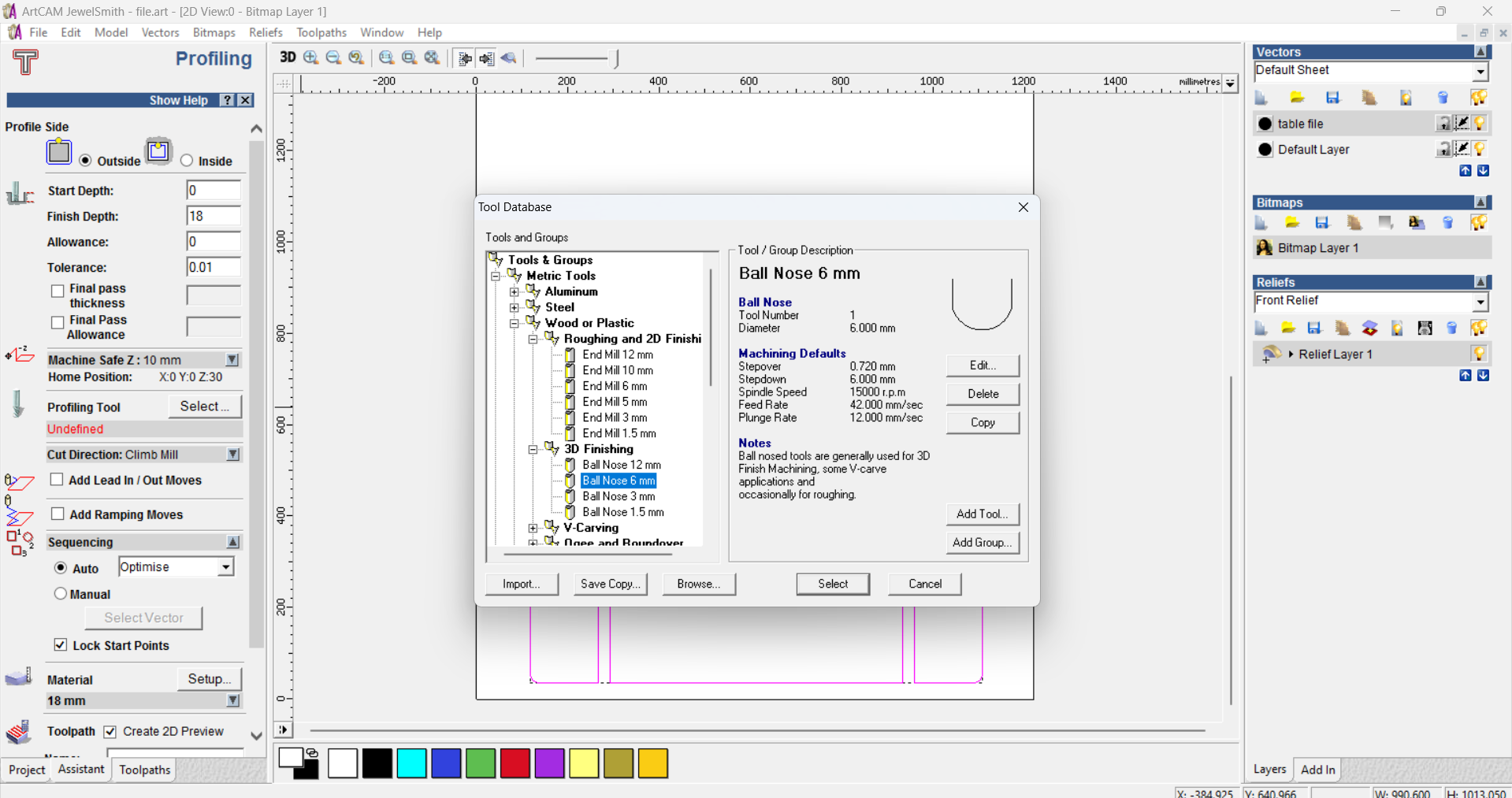
Drill Tool (DT): Used for drilling & routing holes in various materials with precision so i need to use this tool
The machine's versatility is further enhanced by its modular design, which enables easy customization and integration of additional tools and modules based on specific production needs.
Machine :
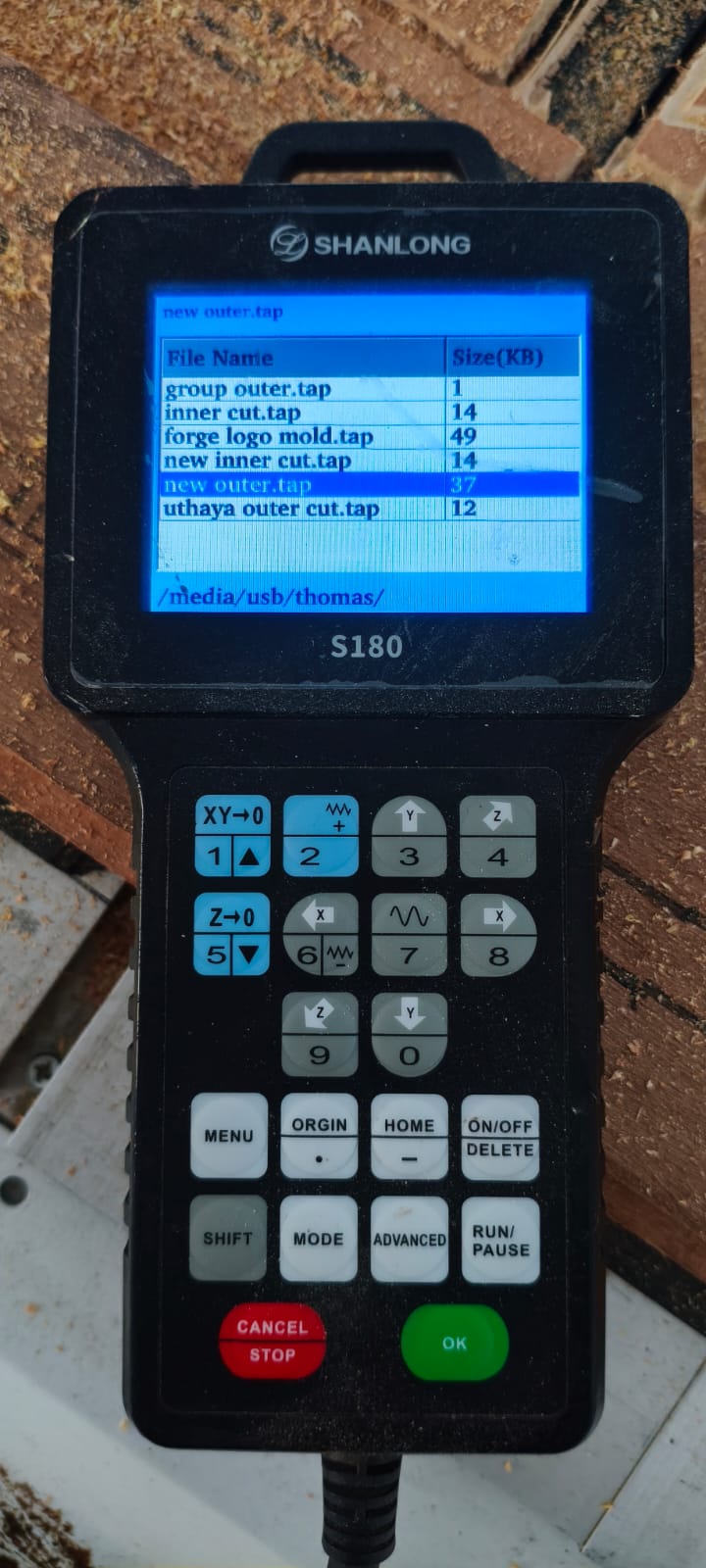
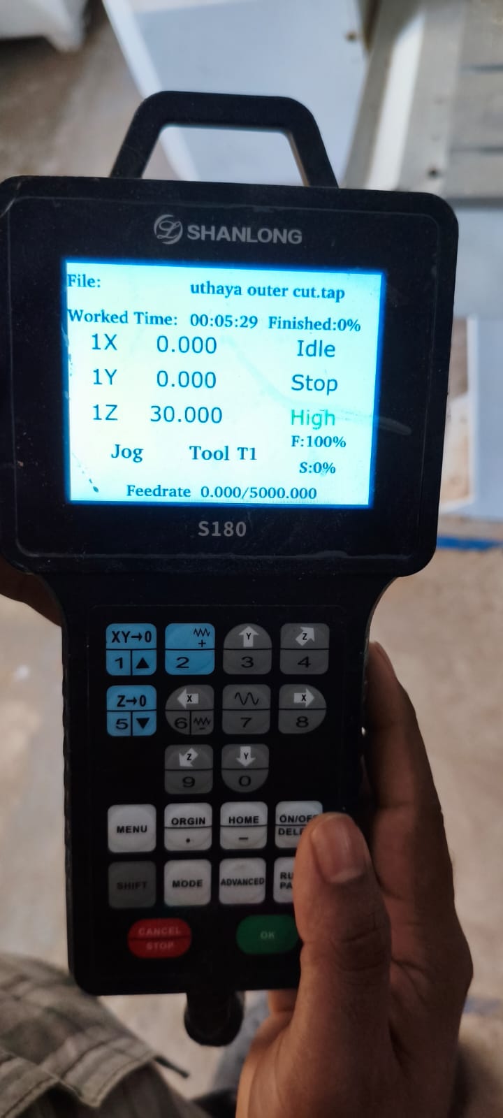
this is the controler it have lot of options and i learned some of them
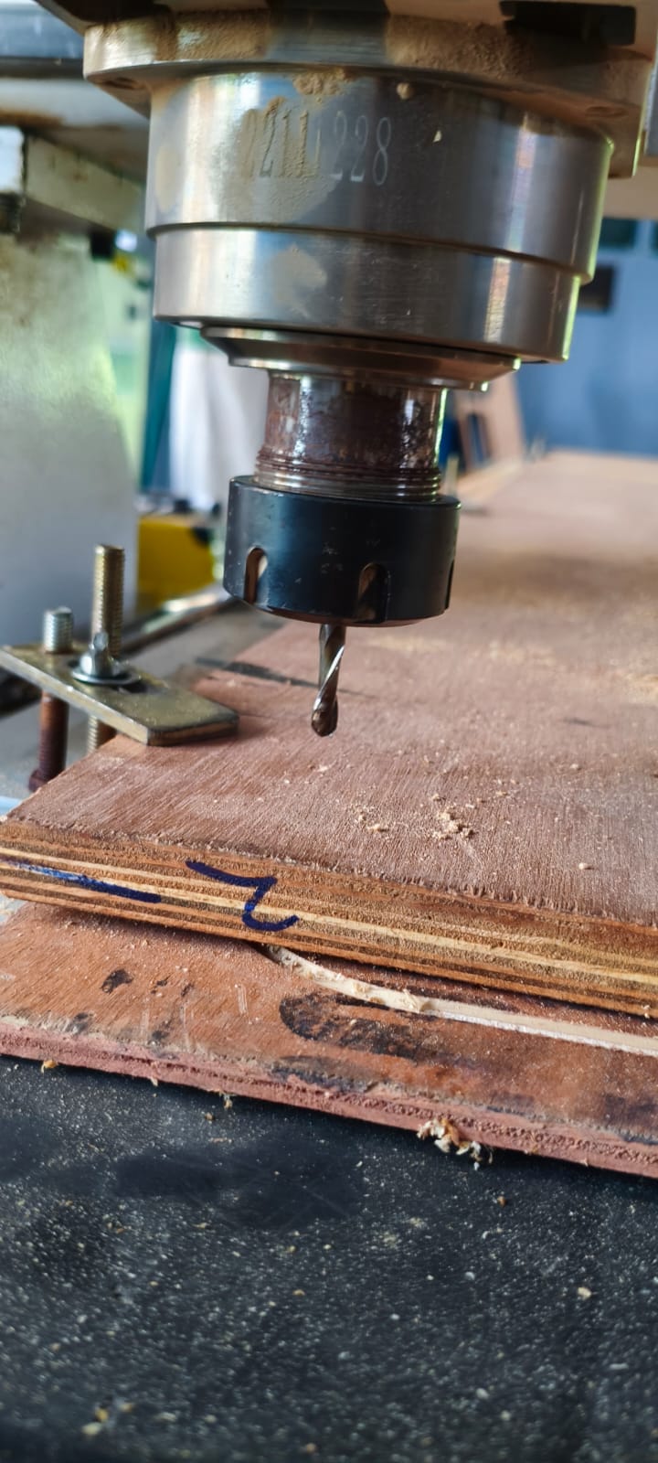
now im putting the drill bit to the origin point
you can see the drill bit on the origin point.
now i opened the loaded file on the contrller
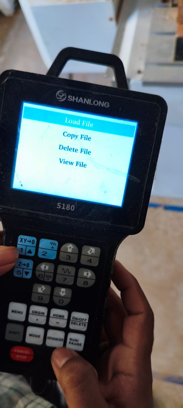
i selected my design file and we are ready to mill
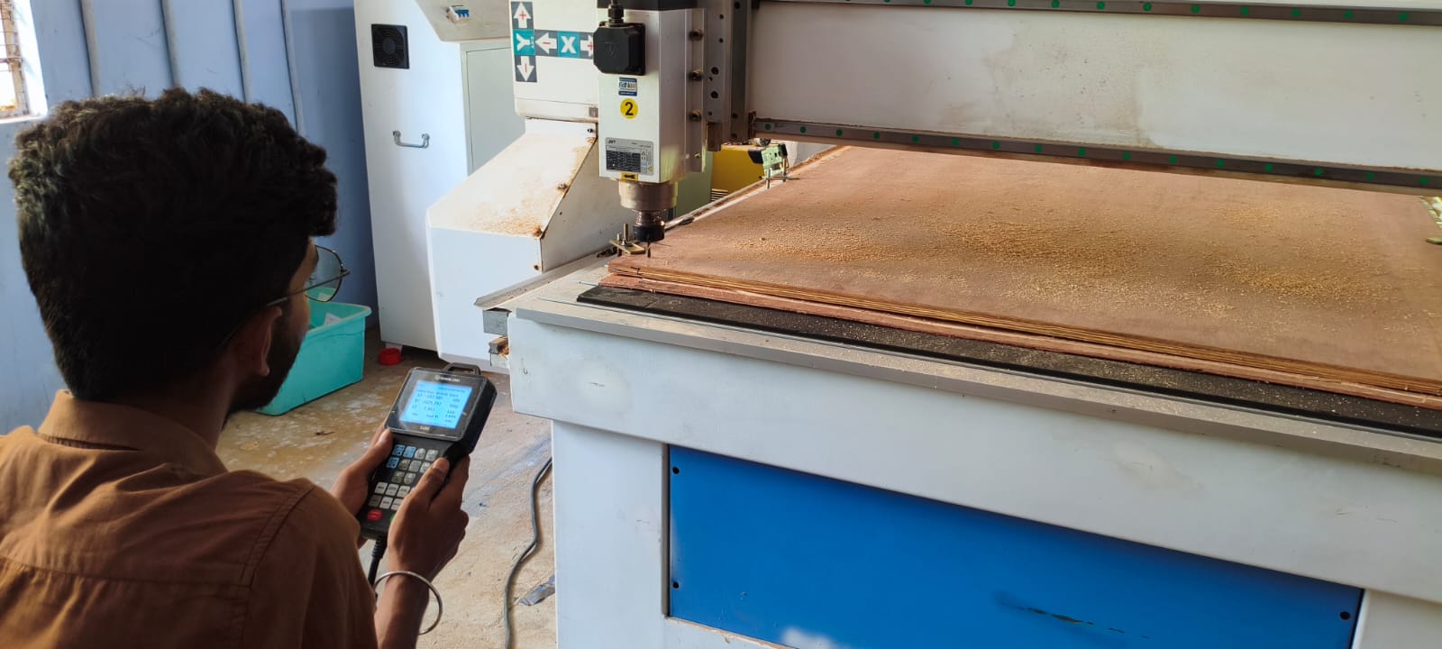
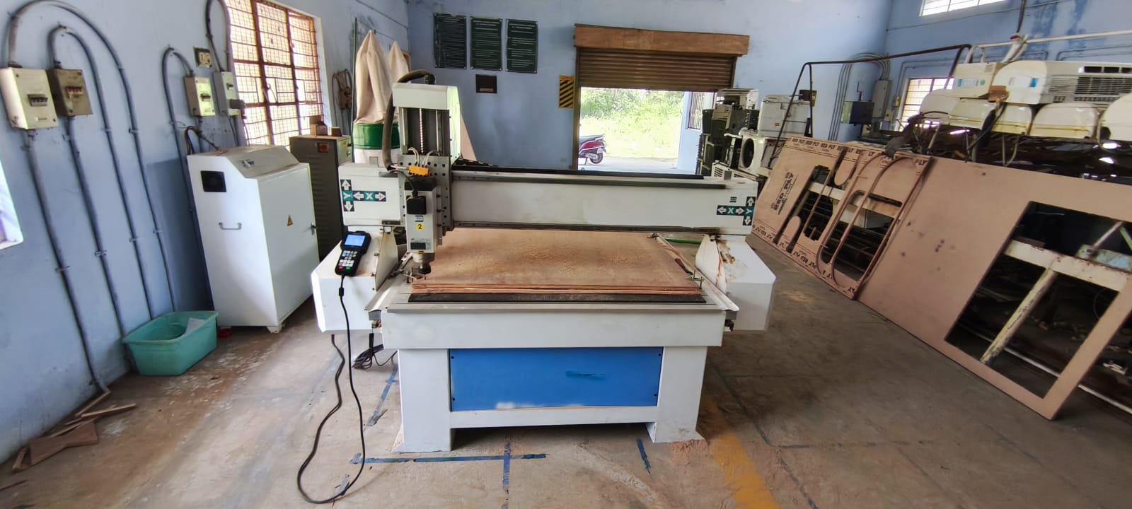
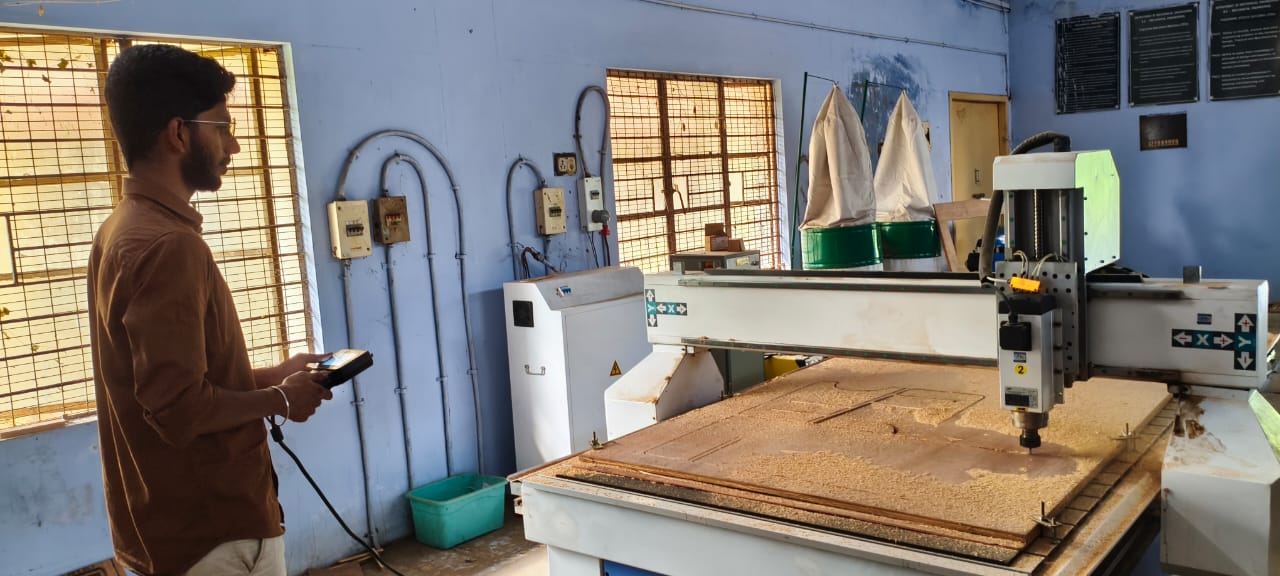
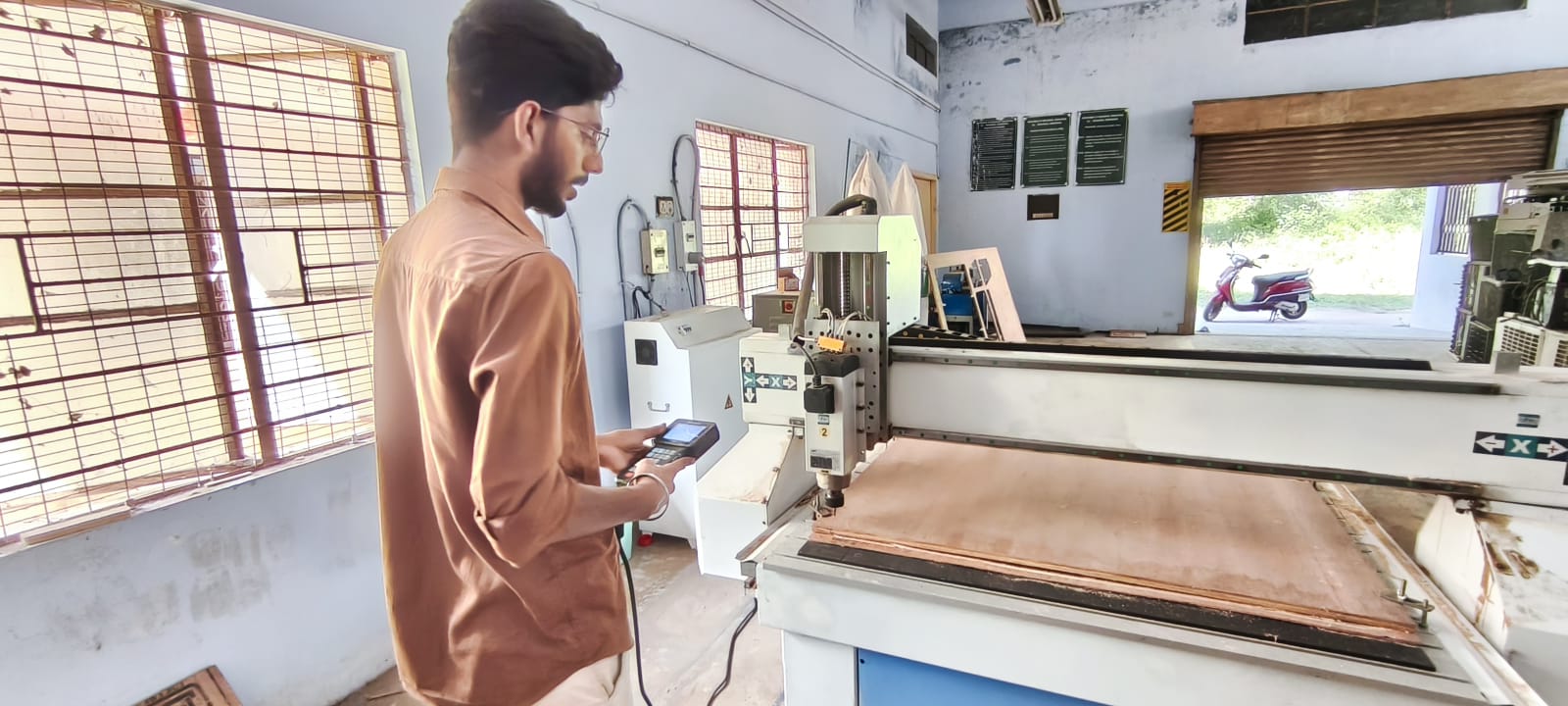
you can see our machine at salem fab lab
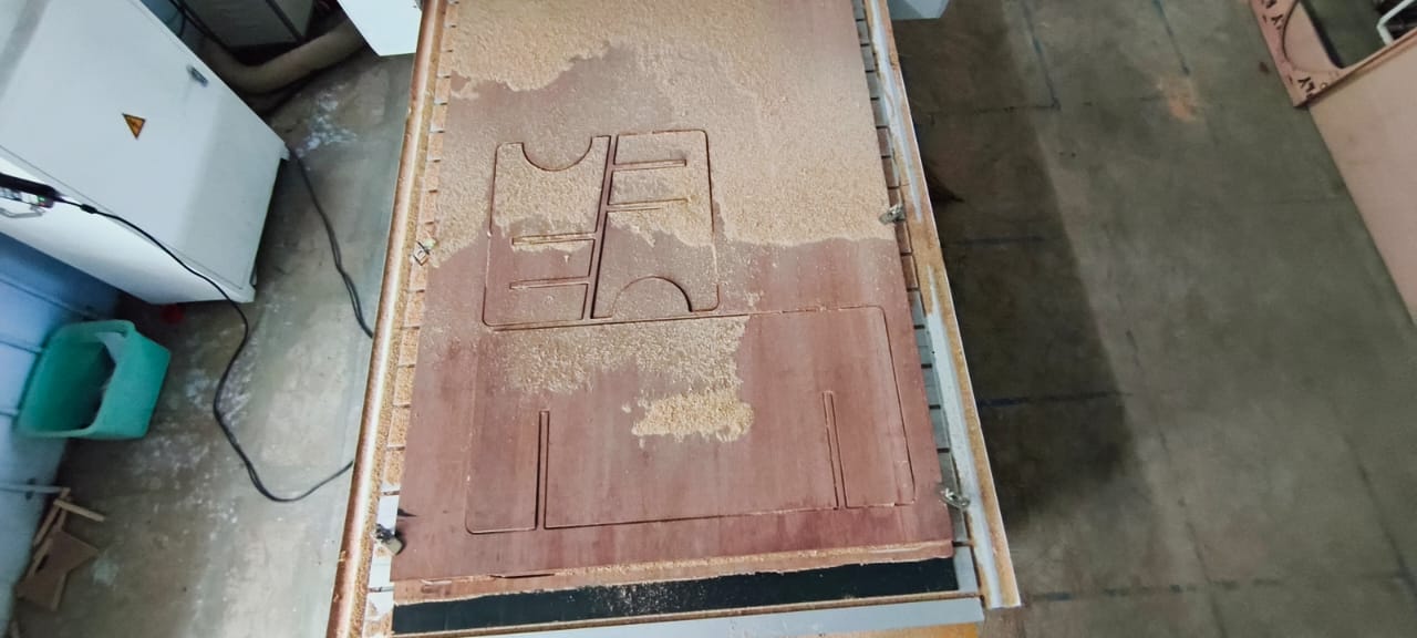
i was started the milling process by pressing run
we need to wait for the mill to done
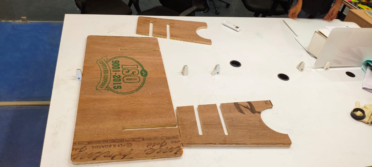
this is the final output after milling
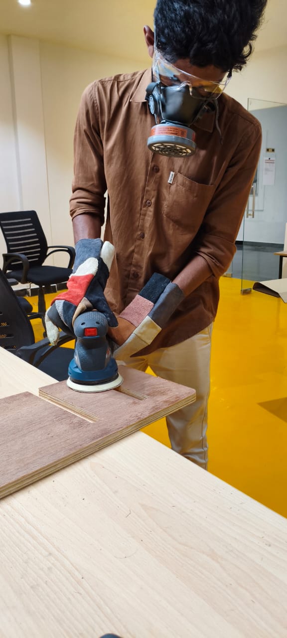
post process:
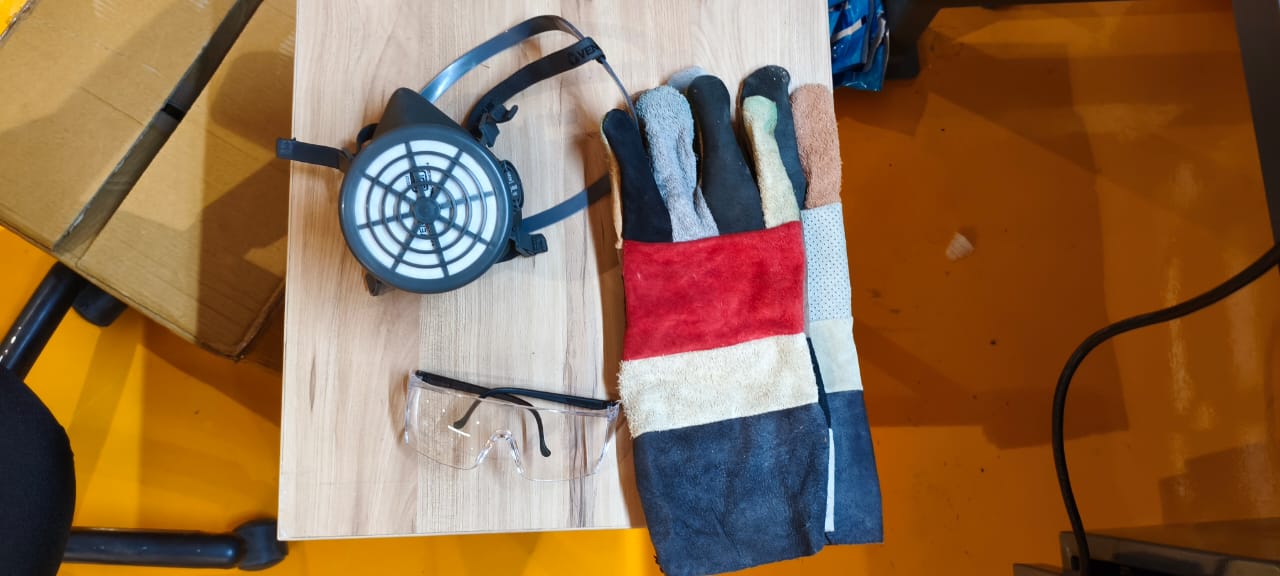
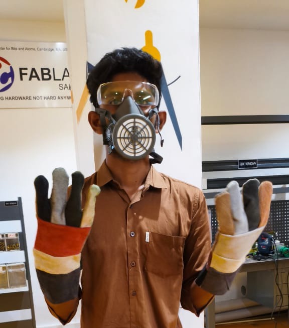
this are the saftey stuffs we have.
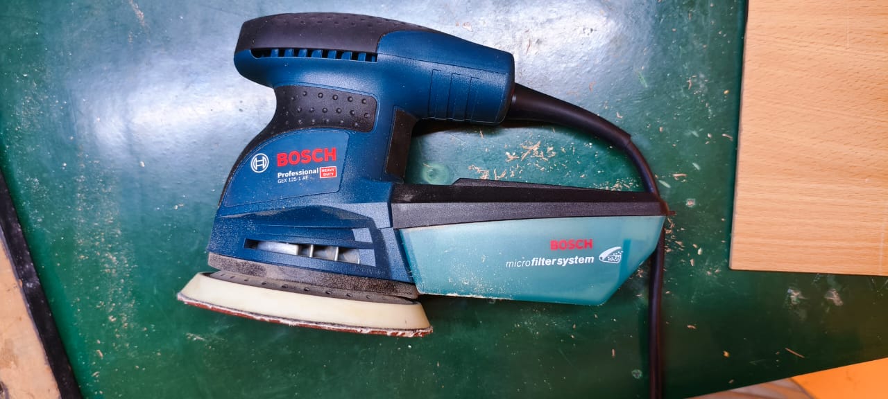
this machine is im going to use it for finishing
wearing saftey equipments looks funny but it saves you from damaging yourself
im removing any burs left on the wood try to giving a smooth finish
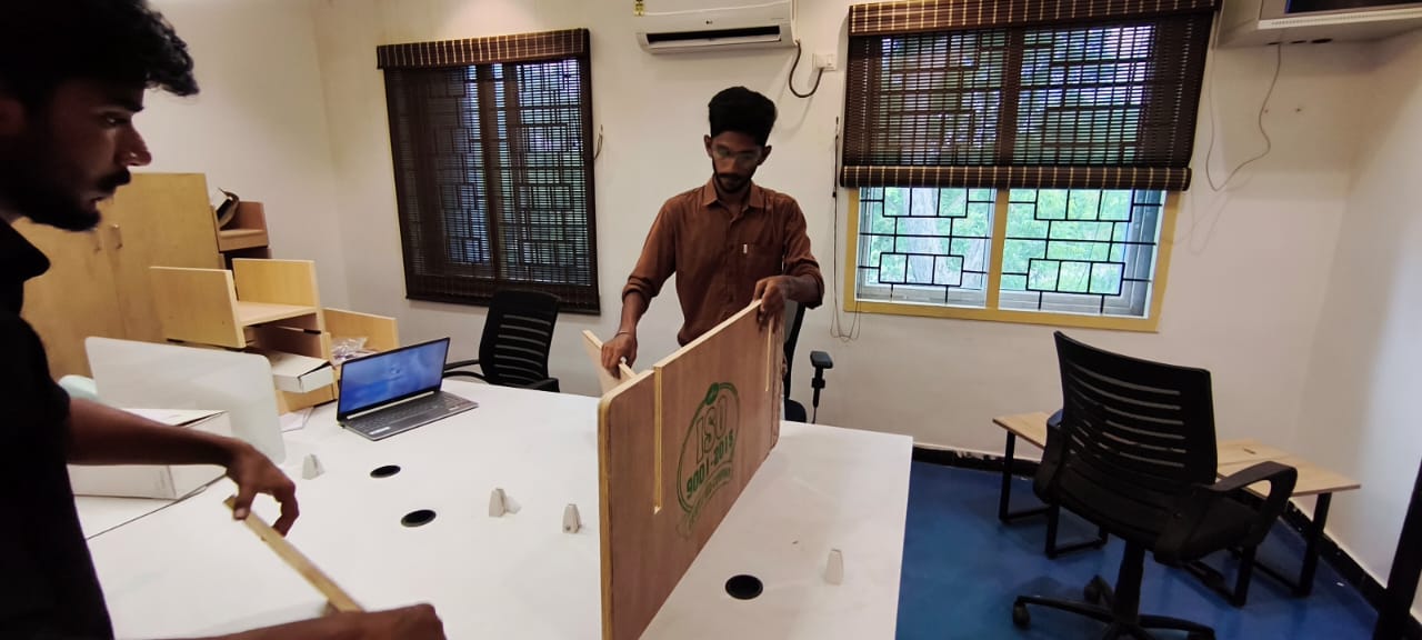
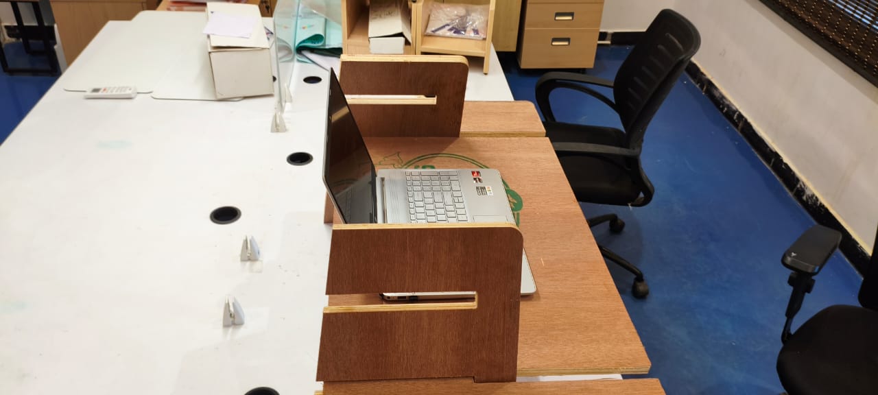
assembling:
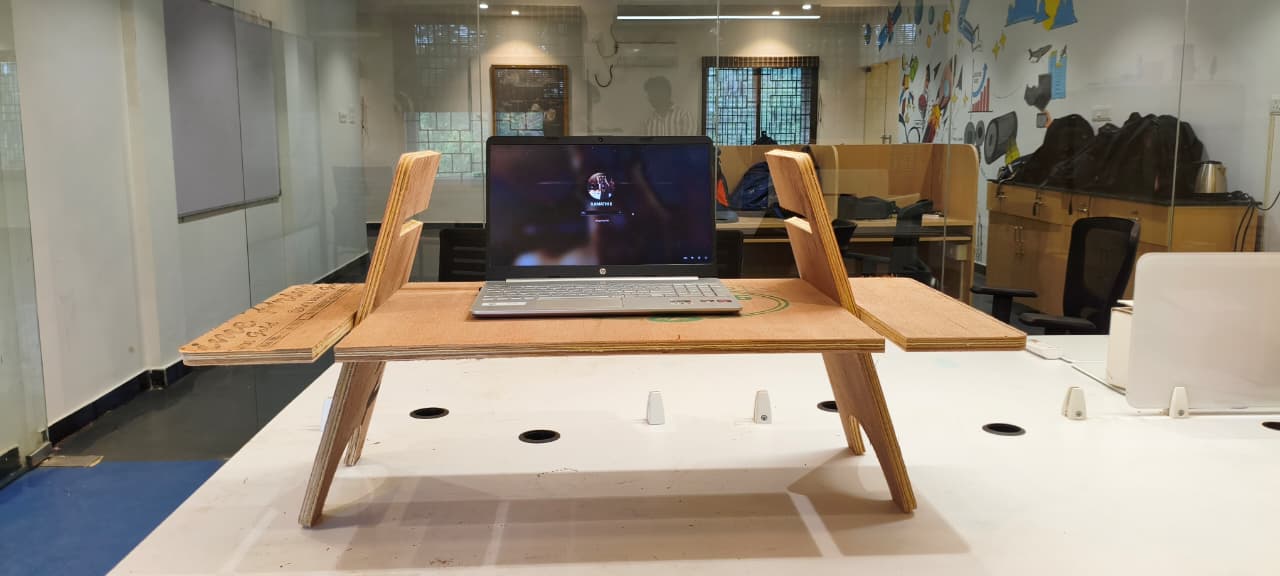
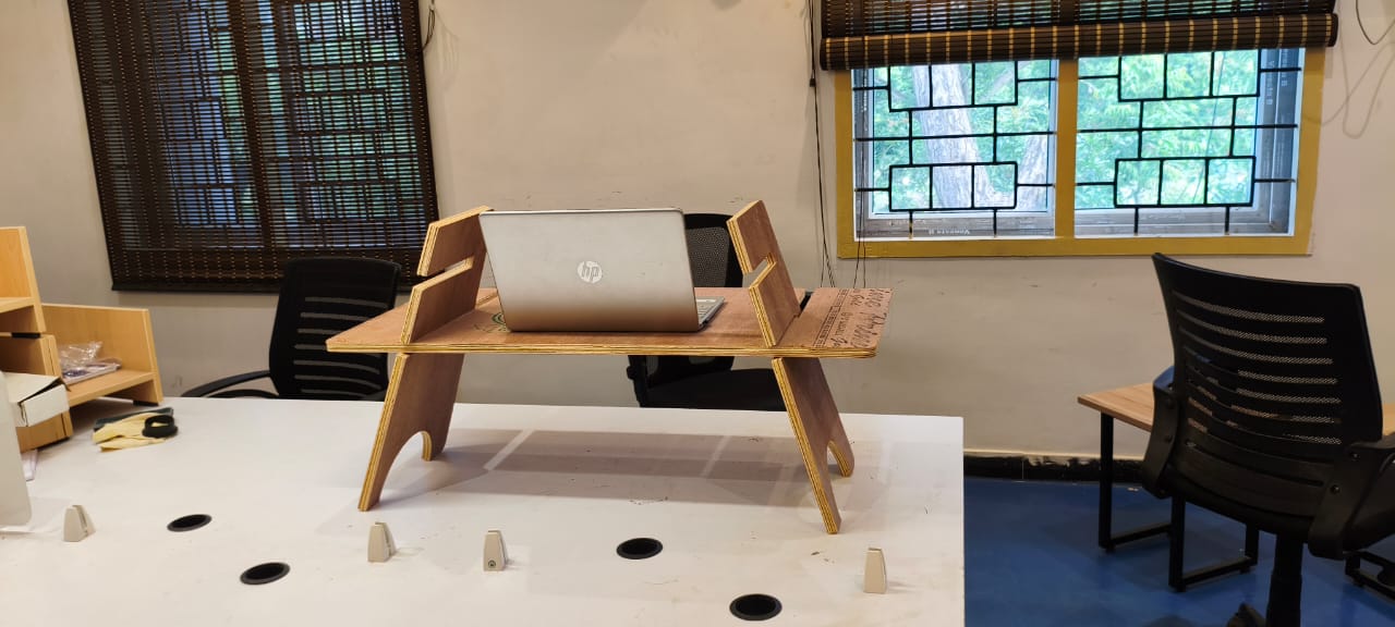
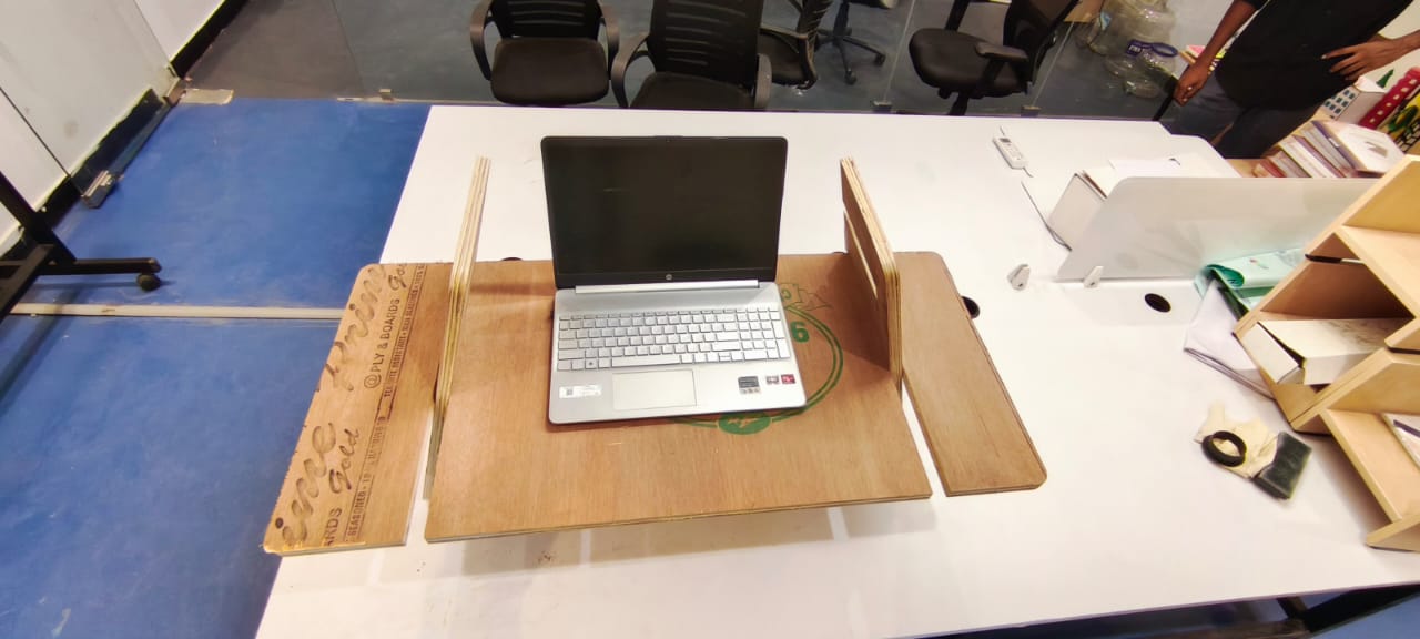
Final output:
Files :
The end of week 7

Fab Academy is an intensive five-month program that teaches students to envision, design and prototype projects using digital fabrication tools and machines. It is a multi-disciplinary and hands-on learning experience that empowers students to learn-by-doing and inspires them to make stuff locally to become active participants in sustainable cities and communities.
Get In Touch
Rathinam nagar,Theni(Dt)-625531, Tamil Nadu, INDIA
+91 8122997014
uthayavelraj@gmail.com
Start a project
Copyright @2025 © Uthaya Velraj. All Rights Reserved.
Designed by Myself