Week 12
Mechanical Design & Machine Design
Welcome to Fab Academy's Machine Design week. Our goal was to design and build a useful machine by combining mechanism, actuation, automation, and application. We identified issues in the lab's thermal cutting machine and designed a safer, more accurate Hot Wire Foam Cutting Machine. Using Fusion 360, we designed the structure, fabricated parts with aluminum profiles and 3D printing, and integrated electronics such as stepper motors, drivers, and Arduino to automate the machine. This week’s documentation highlights our transition from manual testing to a fully automated setup while learning teamwork, design, and machine building skills.
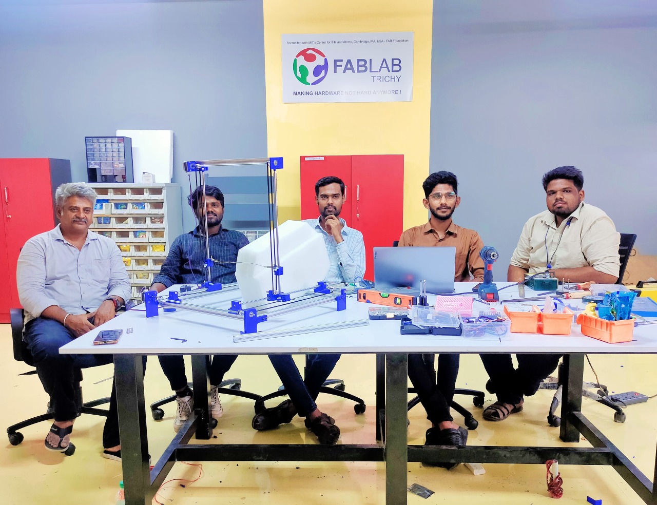
My Hero Shot for this Week
Group assignment :
- Designed and built a Hot Wire Foam Cutting Machine with mechanism, actuation, automation, and application.
- Fabricated and assembled the mechanical parts, and tested the machine manually.
- Added stepper motors, drivers, Arduino, and Universal G-code Sender to actuate and automate the machine.
Individual assignment :
My contribution this week focused on CAD design of the machine structure, assembly of parts, and integration of electronics with Arduino. I documented my learning process and reflected on how the manual testing transitioned into full automation.
Machine Design Process
During the Machining week, our goal was to develop a Hot Wire Foam Cutting Machine. We divided responsibilities among team members, and I was tasked with overseeing the design aspect of the project.
I took the lead in planning the design process, ensuring that the machine’s layout and functionality were prioritized and executed efficiently.
Initial Design in Fusion 360
I started the design from scratch using Fusion 360, a cloud-based 3D CAD, CAM, and CAE platform by Autodesk. This tool allows for parametric, freeform, and mesh modeling, making it ideal for designing and simulating mechanical assemblies.
Base Structure
- Prepared five aluminum profiles: four for the base and one for the workpiece holder.
- Assembled parts using Fusion 360’s assembly feature with the rigid assembly method.
- Used corner brackets from McMaster to secure profiles and maintain alignment.
Linear Motion System
- Designed linear rail rods to guide the hot wire during cutting.
- Created rod holders to stabilize the rails and prevent slippage.
- Mounted linear bearings using a custom bearing block and the slider assembly method.
Motor and Drive Assembly
- Selected a NEMA 17 stepper motor and designed a motor holder.
- Created a base holder for the opposite side for balance.
- Integrated ball bearings using the rigid assembly method.
- Attached components to the threaded rod using the revolute assembly method.
Upper Section and Z-Axis
- Designed the top section to combine the aluminum profile, linear rail rod, and stepper motor.
- Created the Z-axis moving part with a linear bearing for smooth vertical motion.
- Designed a motor-to-screw rod connector for efficient motion transfer.
- Created the Z-axis rotational component to rotate along with the workpiece.
Final Assembly and Visualization
The final assembly integrated all mechanical and motion components into a complete machine. Renderings and an animation were created to illustrate how the parts fit together and operate.
3D Printing & Fabrication
3D Printing with Flash Print
After completing the machine design, I prepared the parts for 3D printing. In our lab, we used the FlashForge 3D printer, so I sliced the models using FlashPrint software. The parts designed in Fusion 360 were exported as STEP files and imported into the slicing software.
I added supports and set the slicing parameters: infill density to 15%, infill pattern to Hexagon, and enabled the raft to ensure the parts adhered well to the build plate. Without a raft, taller parts risk detaching during long prints, so this step is essential for stability.
The nozzle temperature was set to 205°C, and the bed temperature to 50°C. After slicing, the estimated print time was around 25 hours and 45 minutes. The G-code was then exported and loaded into the FlashForge printer, with PLA Pro filament in blue chosen to match our design color.
The printing was started overnight, and in the morning we checked the progress. The print completed successfully in approximately 25 hours and 27 minutes, consuming 73.1 meters of filament.
Fabrication
Once 3D printing was complete, we moved on to fabrication. Using the design specifications, we carefully measured and marked the aluminum parts, readying them for cutting and assembly according to the CAD design.
Outcomes
Group assignments:
- Designed and built a Hot Wire Foam Cutting Machine as a team.
- Automated the machine using stepper motors, Arduino, and drivers.
- Tested the machine for movement, calibration, and safety, and documented the process.
Individual assignments:
- Assisted with CAD design and assembly of machine parts.
- Integrated electronics and contributed to automation.
- Documented my learning and reflected on the design process.