Electronic Production
Home ← →
Objective of this Week
- Characterize the design rules for our in-house PCB production process: document feeds, speeds, plunge rate, depth of cut (traces and outline) and tooling.
- Document the workflow for sending a PCB to a boardhouse
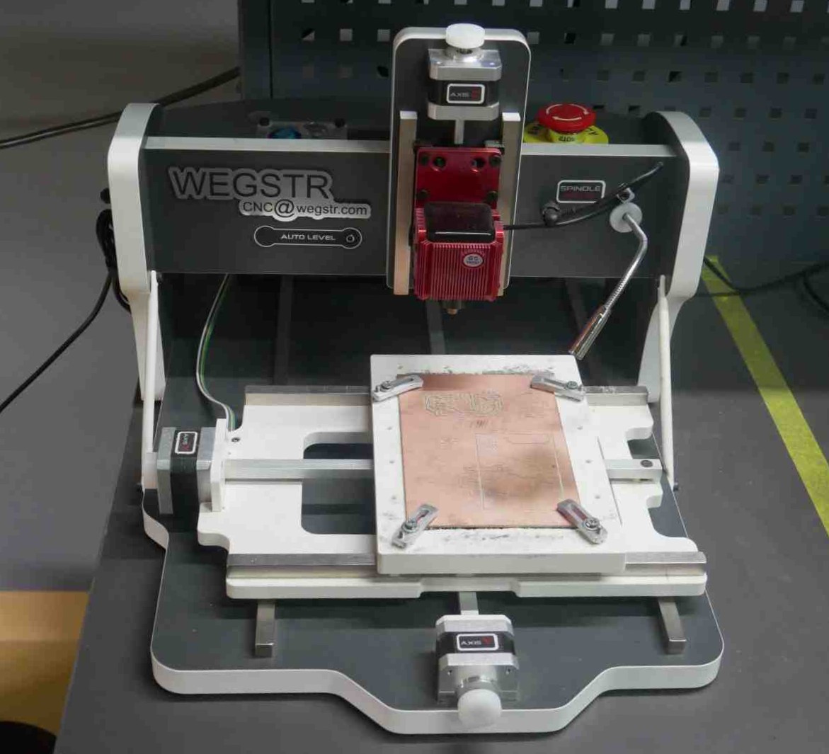
Our Fablab has Wegstr PCB Milling machine
Wegstr PCB milling machine
- The Wegstr PCB milling machine is a compact and precise desktop CNC tool designed for rapid prototyping of printed circuit boards. It eliminates the need for chemical etching by mechanically removing unwanted copper from copper-clad boards, making it an eco-friendly and efficient solution for electronics development. Ideal for small-scale labs, educational institutions, and makerspaces, the machine supports Gerber and Excellon files, allowing direct use of standard PCB design outputs.
- It cost comes around Rs. 3L
Specification:
| Feature | Specifications |
| Working Area | 140 mm(X) * 200 mm(Y) * 40 mm(Z) |
| Spindle | Brushless motor, 11,000 RPM, 3.175 mm diameter |
| Repeatability | ±0.02 mm |
| Stepper Resolution | 0.004 mm per step |
| Printing Speed | ≤ 180 mm/s (Recommended: 60 mm/s) |
| Max Feed Rate | 170 mm/min on all axes |
| Connectivity | USB (compatible with USB 1.x to 3.1) |
| Power Supply | 100–240V AC, 50/60Hz |
| Machine Dimensions | 380 × 460 × 290 mm |
| Weight | 7 kg |
| Software | Wegstr |
| Supported Materials | FR4, aluminum, wood, plastics, brass and copper |
Safety Precautions
| | |
| Ventilation | Ensure good airflow to avoid inhaling dust or fumes from milled materials. |
| Stable Surface | Place the workpiece on a stable suface because the tool tip of the spindle is very sensitive may lead it broken the tool. Firmly clamp to avoid movement during milling |
| Electrical Safety | Use the original power supply and avoid overloading sockets. |
| Check bit condition | Dull or damaged bits can not able to give the proper milled boards |
Design Rules
Minimum Trace Width & Spacing
- Typically ≥ 0.25 mm (10 mil) for standard V-bit milling.
- Ensure trace-to-trace and trace-to-pad spacing is also ≥ 0.25 mm.
Pad Size & Hole Diameter
- Pads should be at least 0.5 mm larger than the hole.
- Minimum drill hole diameter = 0.8 mm (varies by tool).
Board Edge Clearance
- Keep traces and components ≥ 1 mm away from the PCB edge to avoid cutting damage.
Copper Isolation Width
- Isolation between traces (removed copper) should match the tool diameter, e.g., 0.4 mm if using a 0.4 mm tool.
Tool Path Overlap
- Ensure sufficient overlap during isolation to fully remove copper between traces.
Design Test
As first we test our design whether is it properly mill or not
We take out the PCB design which is Manikandan designed for his assignement
Exported it into the SVG format and for the further milling operation we should do the tool path (G-code).
For the tool path we use the MODS which is developed by fab community.
Open the Mods in web browser, then right-click to open a program and go to the G-code 2D PCB Milling, after enter into that load files PNG/SVG for processing (Right click>Program>open program>G-code - mill 2D PCB)
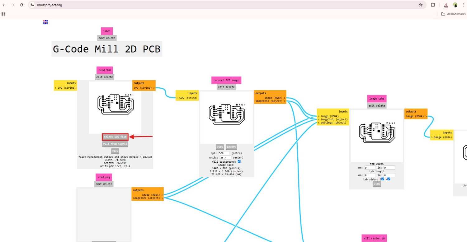
The we set the parameters according to the design trace we gave in PCB design.
So for the milling operation we select the tool size 1/64
We take the V-bit 30 degree, then in V-bit calculator you should calculate the required parameters according to your design.
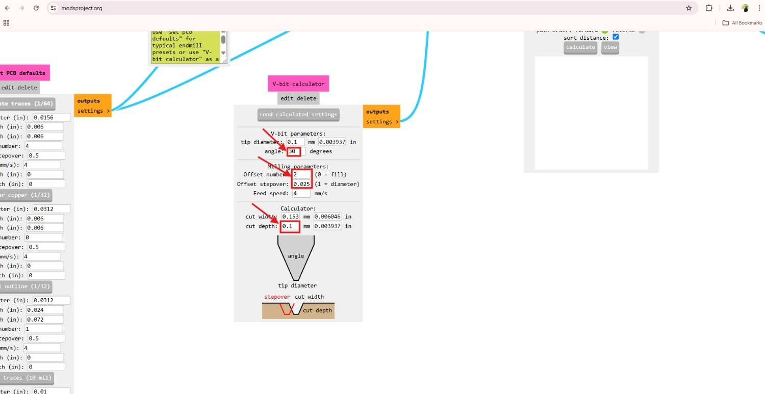
We check the different parameters for our milling machine, so we can figure out which one will be the right one.
After give the one set of experimental parameters we download it.
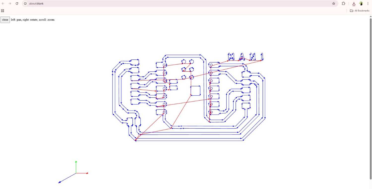
Then open and load it into the Wegstr software,
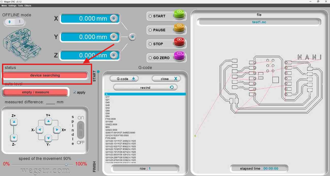
We set the copper board in the milling machine bed rigidly
Then we adjust the spindle height and position for cutting operation through the Wegstr software, in our machine we have the auto leveling option but unfortunately we miss the leveling wire in lab, so we set the height manually.
We first adjust the V-bit 30 degree tool in the spindle and move the spindle downward slowly, after we get the sense to touch the tool tip in copper board we manually loosen it and ensure is it touching or not.
Don’t give too much depth because the tip of the tool is very sensitive so it will be broken easily, and the cost of that tools also high cost to purchase. Therefore use it properly with careful approach.
Set the position as zero otherwise the tip will go agian the last setted position.
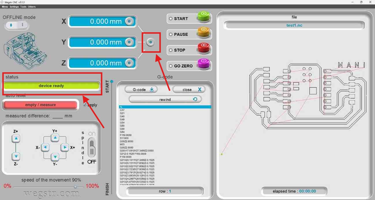
Then we gave start, the spindle was rotating at high speed, we observe the tool running direction and cut of depth.
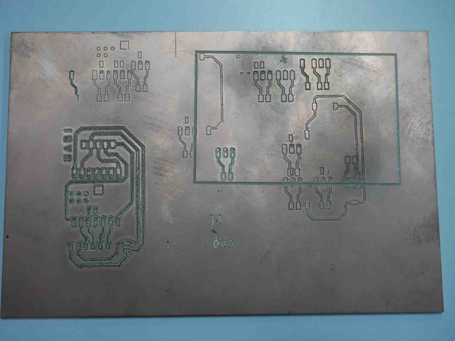
After finishing that we took out from the machine whether it is good one or not
It came very bad, the trace are get broken by the spindle movement and the cut of depth is too much, so again we go to the Mods and change some parameters again.
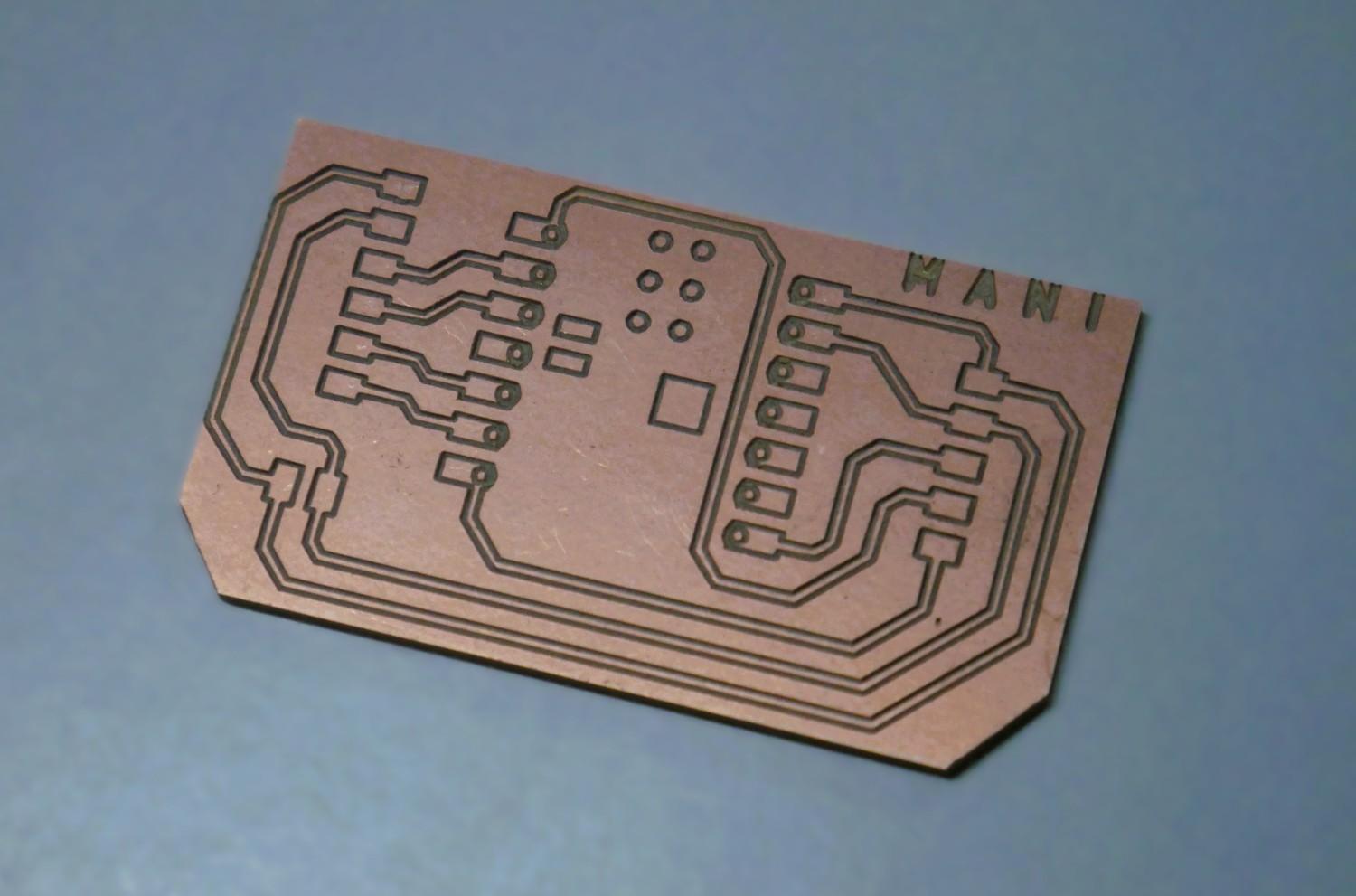
After trying so many attempts we figure out the best one milled operation
For the Proper cutting process you can see Manikandan Electronic Production page for this PCB board.
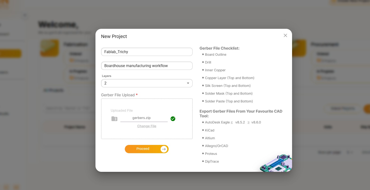
Workflow for Sending a PCB to a Boardhouse
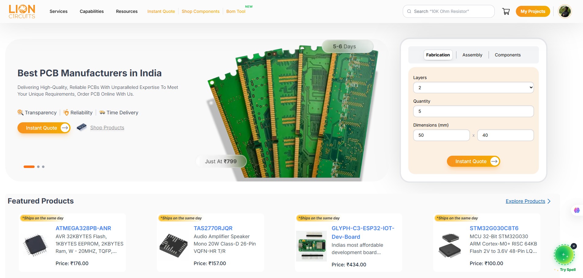
Lion Circuits
As part of understanding the boardhouse manufacturing workflow, we explored LionCircuits, an Indian PCB fabrication and assembly service.The platform provides PCB fabrication, PCB assembly, component sourcing, and turnkey manufacturing services through an online ordering system. Customers can upload Gerber files, review manufacturability feedback, configure board specifications, receive instant quotations, and place manufacturing orders.
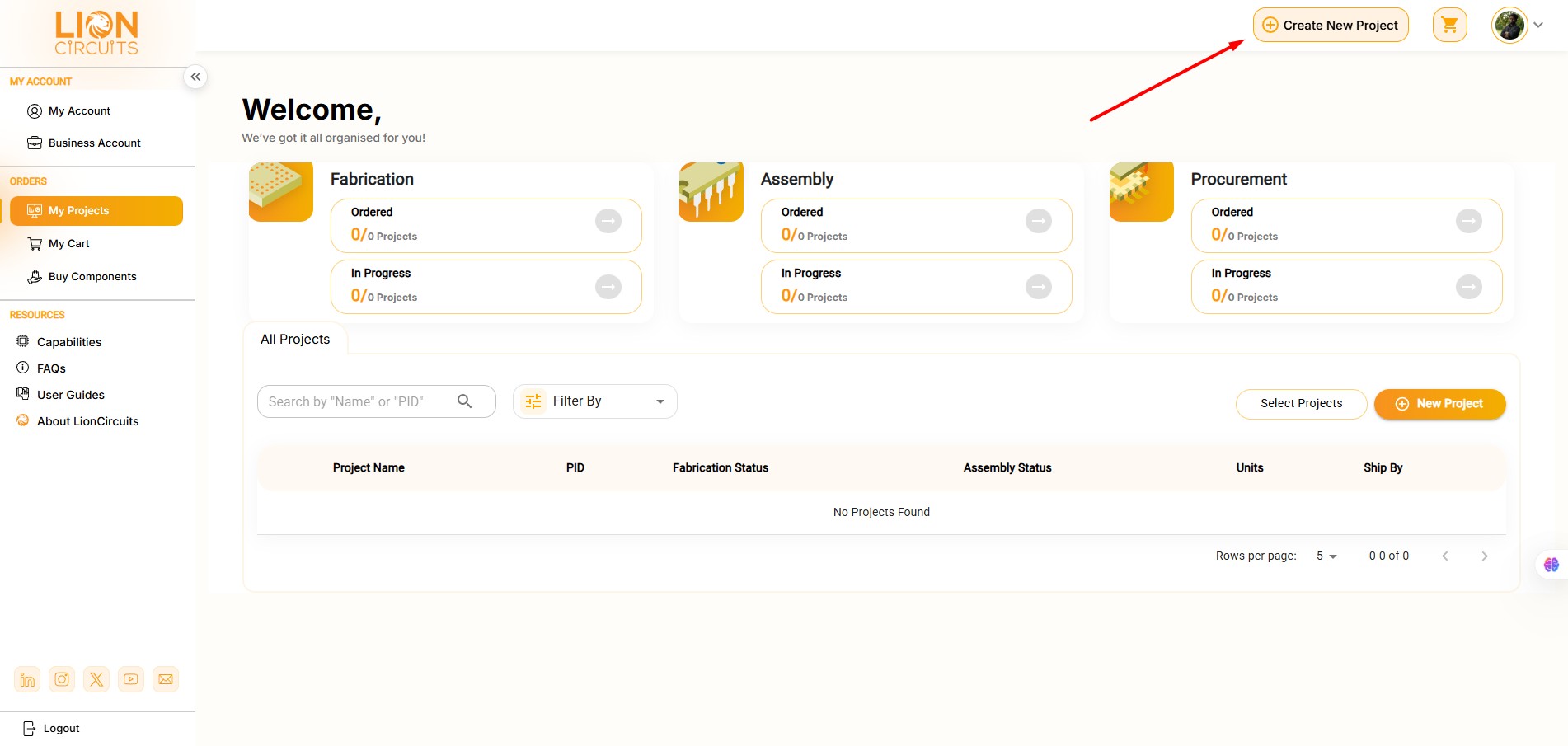
So we choose the Lion Circuits for our boardhouse manufacturing, we login the website
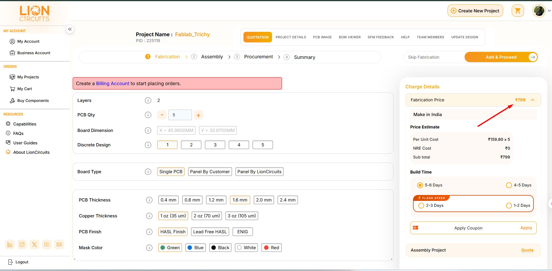
Once we set up we can able to see the price details on right side.
Challenges
At the time of this assignment we face one issues so our assignment also getting late
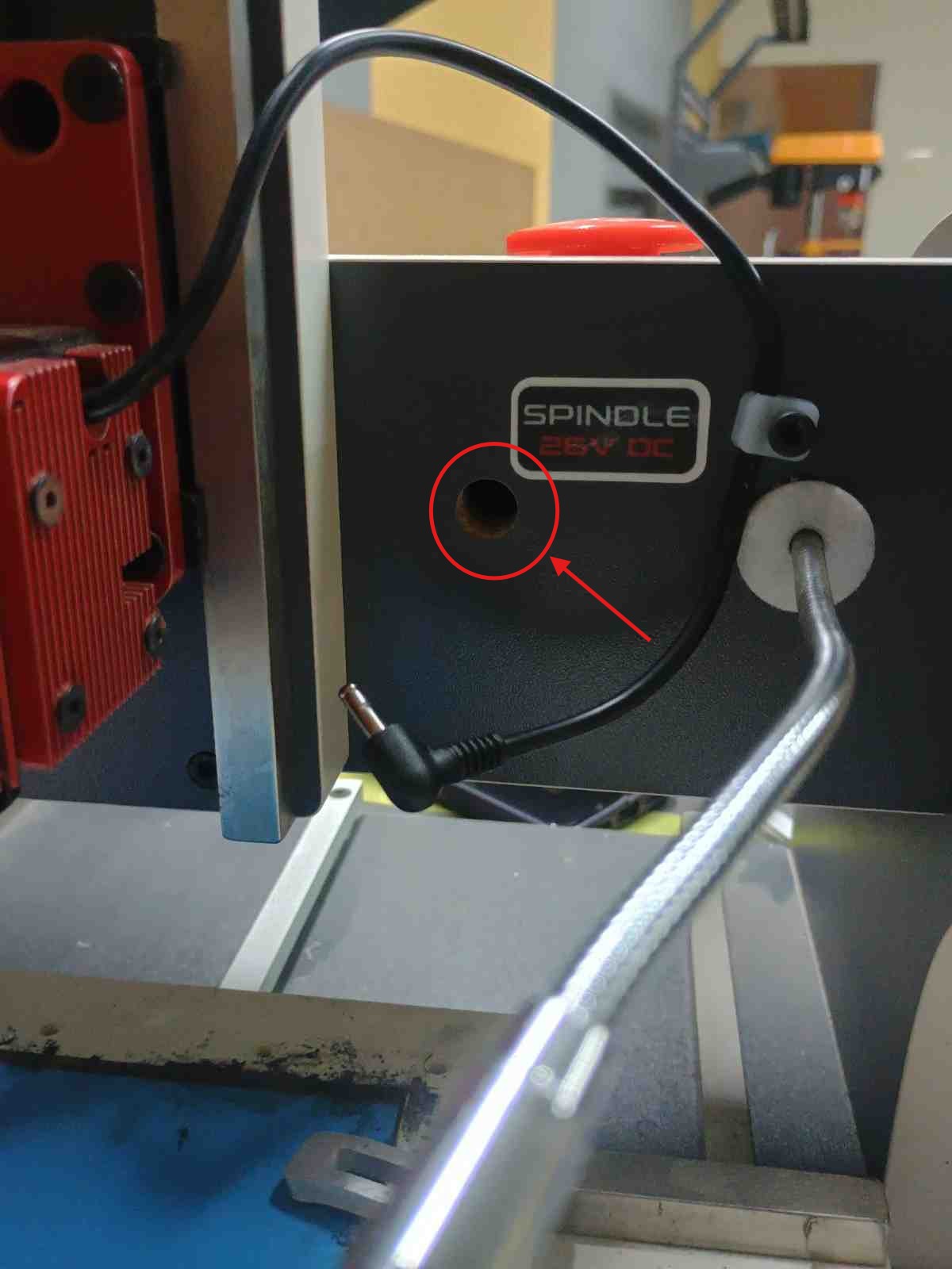
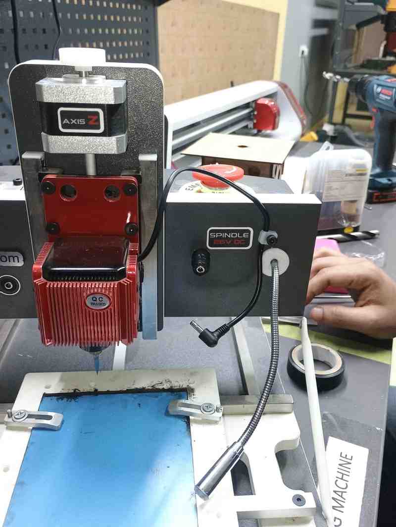
In our machine the spindle power supply pin is slighlty go inside the machine cover, we try so many attempts to take out but the end it is really hard to push back.
So we determined to open our machine cover fully, we peel off the sticker which is cover the screws
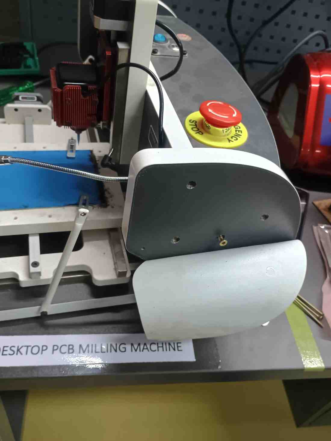
Then we take out all the screws from the machine one side, now we able to see that jack condition and try to do take out by using the tweezer from the cover so many times still its very hard
There is only two option we have, first one we should remove the front screws from the machine and took out complety that layer so we can easily push by using our hands.
Otherwise we only enlarge the hole diameter little bit. So in our case the second option is best as we felt.
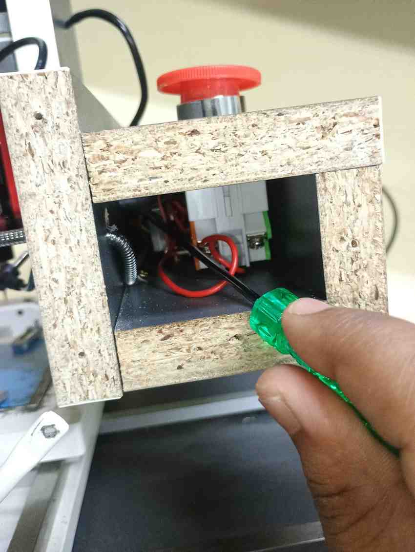
So we go with the second option do fininsh it quickly, we take the driller and set the drill bit which is only slighlty enlarge compare to the existing hole
After drilled it we took out the jack barrerl easily from the machine cover. Now we can use the machine without any disturbance.
Conclusion
Learning outcomes
- We came to know about the PCB production process both Milling and Etching process
- In Etching process we learnt about some chemicals by using search engine
- In Milling process we learnt about Milling macines, that’s parameters and specifications, more deeply in spindle speed and its pressure whenever it millling the board
- We accidentaly break 2 tools at the time of milling and Z axis movement for set the zero position
- Know more about the tools types and it’s usage
- After attending the design test multiple times we know about our machine capability
- Still don’t know about the post processing process to finish it like industrial grade