Input devices
Home ← →
Objective of this Week
- Probe an input device(s)'s analog levels and digital signals
Oscilloscope
An oscilloscope is an electronic test instrument that displays and analyzes the waveform of electronic signals. It shows how signals change over time on a screen, with the horizontal axis (X) representing time and the vertical axis (Y) representing voltage.
- By using the Oscilloscope we can measure signal’s amplitude, frequency, and noise.
- We can diagnose circuit issues like voltage drops, signal distortion and timing errors.
- To View analog or digital waveforms in real-time Oscilloscope is really useful.
In our lab we have Mixed Signal Oscilloscope Tektronix - MSO-22
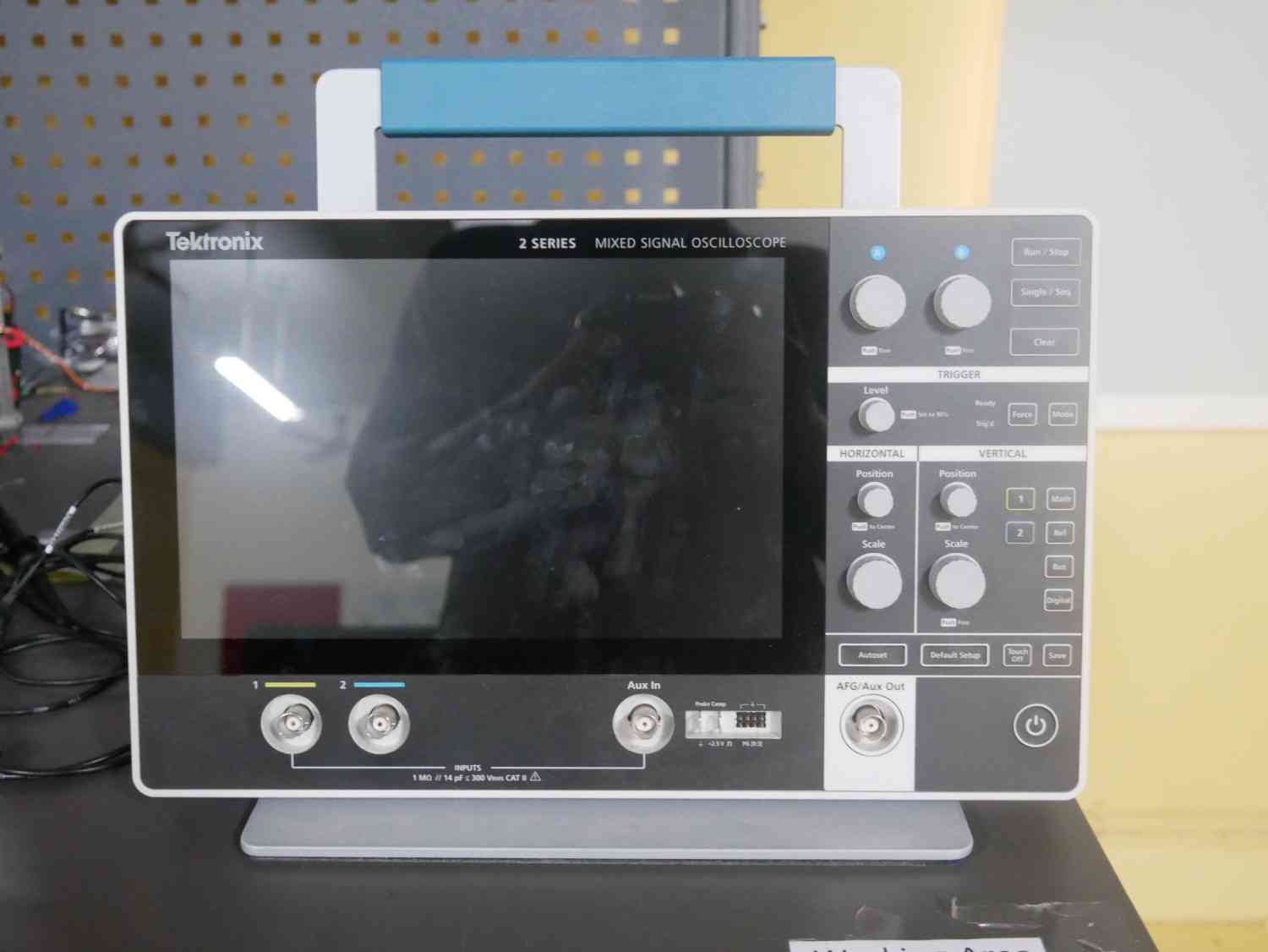
Specification
| Parameter | Details |
| Analog Bandwidth | 70 MHz (upgradeable to 100/200/350/500 MHz via license) |
| Analog Channels | 2 |
| Digital Channels | 16 (optional, with logic probe) |
| Max Sample Rate | 2.5 GSa/s (1 channel), 1.25 GSa/s (2 channels) |
| Record Length | 10 million points per channel |
| Vertical Resolution | 8-bit (standard), up to 16-bit (high-res mode) |
| Waveform Capture Rate | > 4,000,000 wfms/s |
| Display | 10.1” capacitive touchscreen (1280 × 800 resolution) |
| Trigger Types | Edge, pulse width, runt, timeout, logic, setup/hold, rise/fall, parallel bus |
| Math Functions | Add, subtract, multiply, divide, FFT, custom equations |
| Protocol Decoding (Optional) | I²C, SPI, UART, CAN, LIN, SENT, 10Base-T1S |
| Optional Features | AFG (50 MHz), Digital Pattern Generator (4-bit), DVM |
| Connectivity | USB 2.0 (host & device), Ethernet (LAN), VNC remote control |
| Power Supply | External AC adapter, Optional battery (up to 8 hrs use) |
| Included Accessories | TPP0200 probes (1 per analog channel), power adapter, manuals |
| Approximate Price | ~$2,130 USD |
Types of Oscilloscopes
| Type | Purpose |
| Analog Oscilloscope | Uses CRT; older but good for visualizing simple analog waveforms |
| Digital Storage Oscilloscope (DSO) | Converts signals to digital for storage and advanced analysis |
| Mixed Signal Oscilloscope (MSO) | Combines analog and digital signal analysis |
| Handheld Oscilloscope | Portable and battery-powered for field work |
| PC-Based Oscilloscope | Uses computer display and processing for signal analysis |
Multimeter
A multimeter is an electronic measuring instrument used to measure electrical parameters such as voltage, current, resistance, and continuity. It is one of the most common tools used in electronics for testing, troubleshooting, and circuit verification.
- By using a multimeter we can measure DC and AC voltage levels.
- We can measure current consumption of electronic circuits.
- We can check the resistance of components such as resistors, potentiometers, and sensors.
- We can verify electrical connections using continuity testing and identify wiring faults.
- To measure analog voltage levels and digital HIGH/LOW signals from input devices, a multimeter is very useful.
In our lab we have a Digital Multimeter.
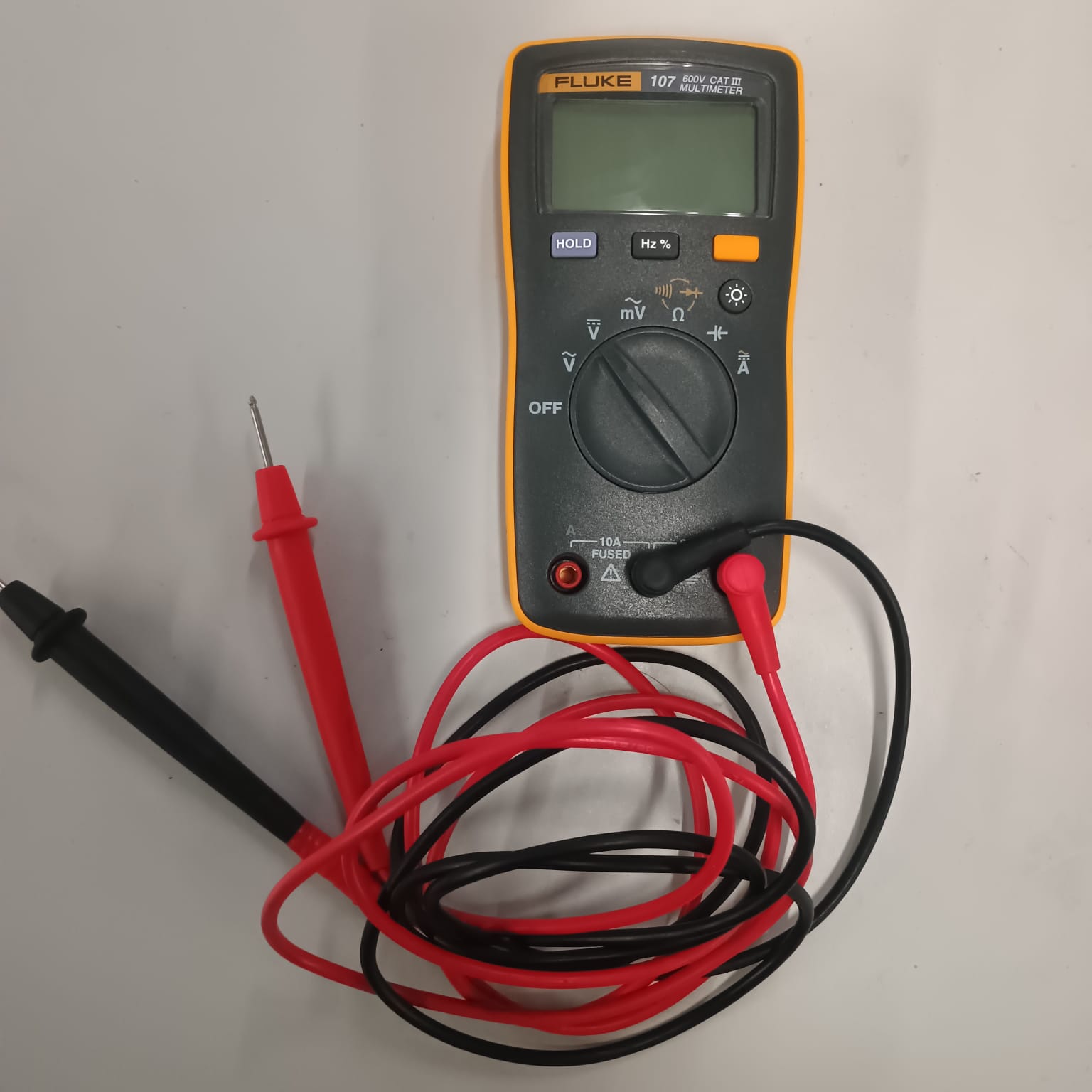
Specification
| Parameter | Details |
| Model | Fluke 107 Digital Multimeter |
| Display | 6000-count digital display |
| DC Voltage | Up to 600 V |
| AC Voltage | Up to 600 V |
| DC Current | Up to 10 A |
| Resistance | Up to 40 MΩ |
| Capacitance | Up to 1000 µF |
| Frequency Measurement | Up to 100 kHz |
| Continuity Test | Yes |
| Diode Test | Yes |
| Data Hold | Yes |
| Safety Rating | CAT III 600 V |
| Power Source | 2 × AAA Batteries |
| Weight | Approximately 200 g |
| Approximate Price | ₹6,000 – ₹8,000 |
Components for Assignment
- XIAO ESP32S3 board
- Potentiometer
- Push Button
- Resistor
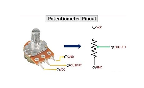
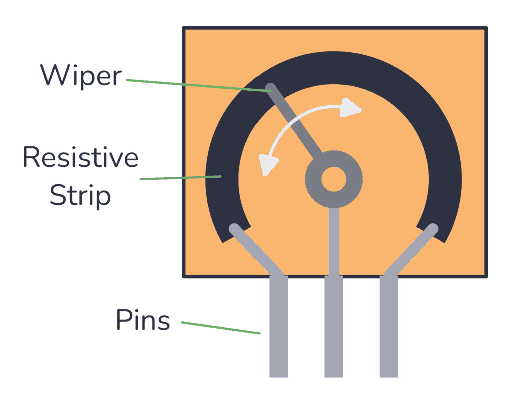
Potentiometer
A potentiometer is just a variable resistor used to adjust voltage levels or control electrical devices
Push Button
A push button is a momentary switch that makes or breaks an electrical connection when we are pressed.
Programming
int analogValue;
int buttonState;

void setup() {
  delay(1000); // Give USB time to initialize
  Serial.begin(9600);
  pinMode(A0, INPUT);
  pinMode(D1, INPUT);
  Serial.println("Ready");
}

void loop() {
  analogValue = analogRead(A0);  // Potentiometer
  buttonState = digitalRead(D1); // Pushbutton (0 or 1)

  Serial.print("Potentiometer: ");
  Serial.println(analogValue);
  Serial.print("Button: ");
  Serial.println(buttonState);

  delay(500);
}
Testing with Oscilloscope
At first check with the Serial monitor
Then connecting it with Oscilloscope and see the signal function
Testing with Multimeter
We used a digital multimeter to measure the voltage levels generated by the input devices.
The push button was connected to a digital input pin.
Using the multimeter, we measured:
The potentiometer was connected between 5V and GND, and the output pin was connected to the multimeter probe.
By rotating the potentiometer knob, we observed that the output voltage changed continuously between approximately 0V and 4.6V.
Conclusion
Learning outcomes
- By using the multimeter and oscilloscope, we checked the push button and potentiometer as input devices.
- We measured the voltage levels of the potentiometer and push button using the multimeter.
- We monitored the input values through the Serial Monitor and verified the signals using the oscilloscope.
- We understood the difference between analog and digital signals by observing their voltage levels and waveforms.
- We detected the input signals and verified their proper functionality.