Progress
Week 1: Paper sketch
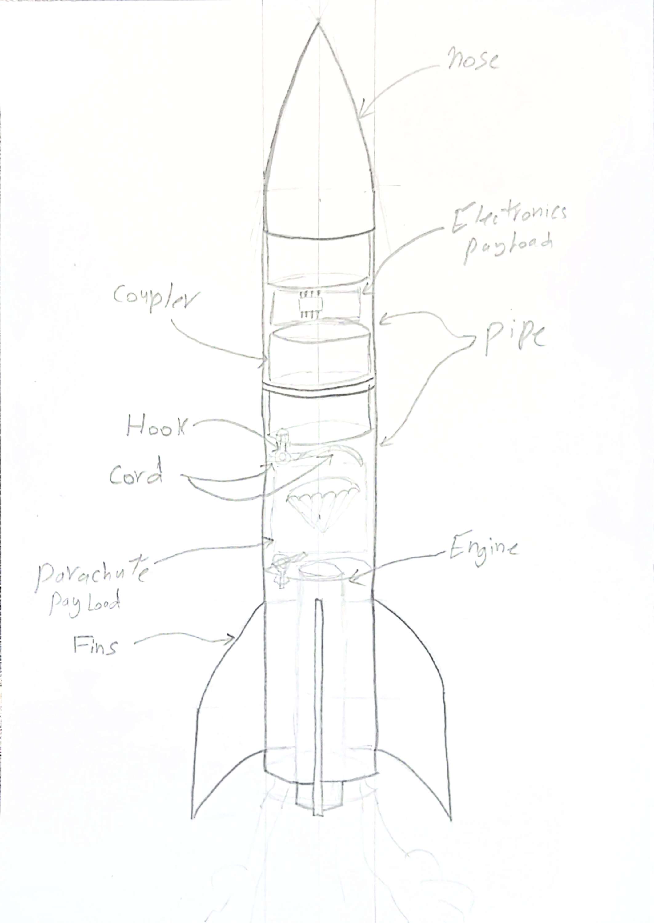
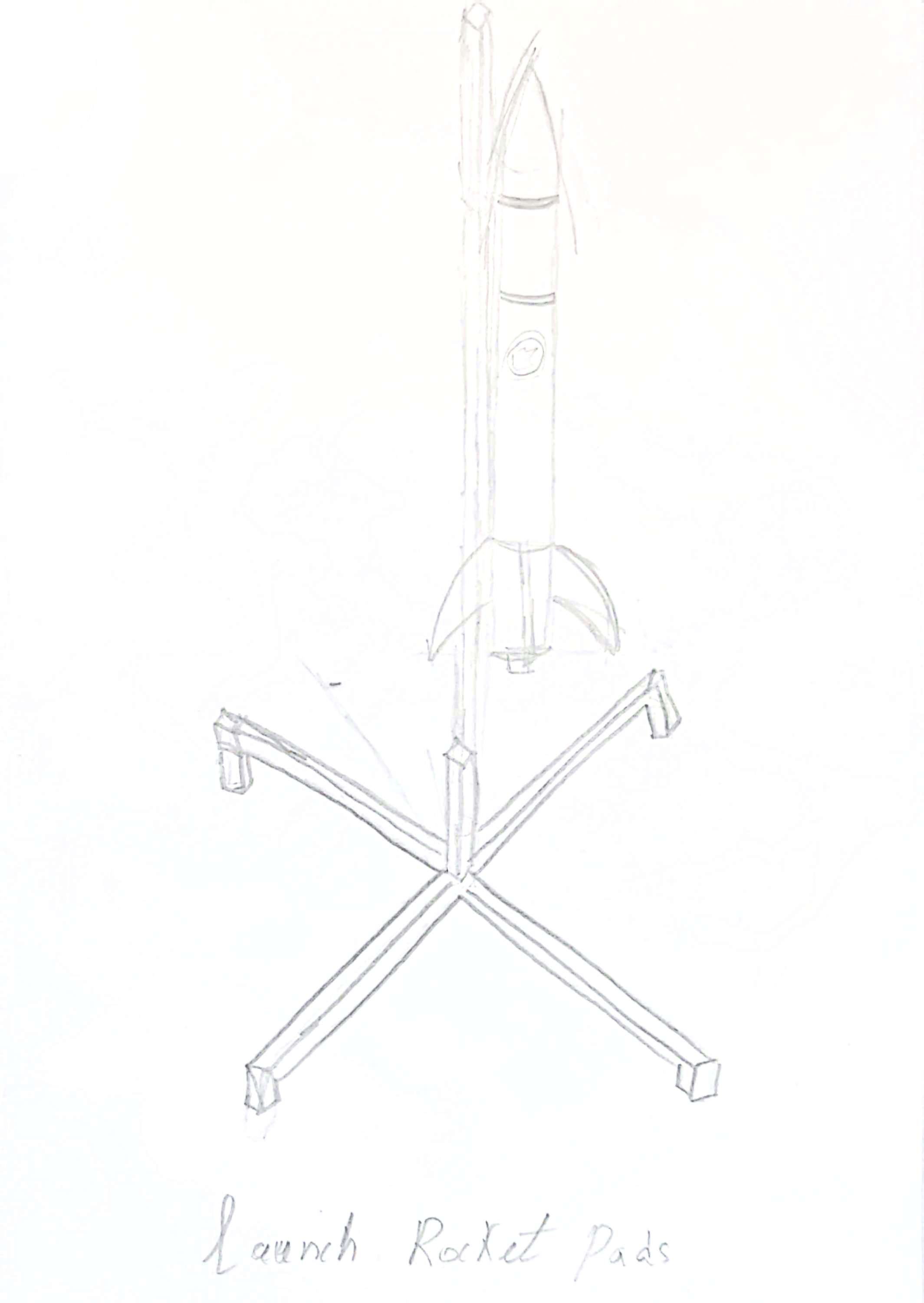
Paper sketch
Paper sketch:
Week 2: Mission Logo + Simulation + 3D CAD + Poster
Mission Logo Design:
Mission Logo Design:
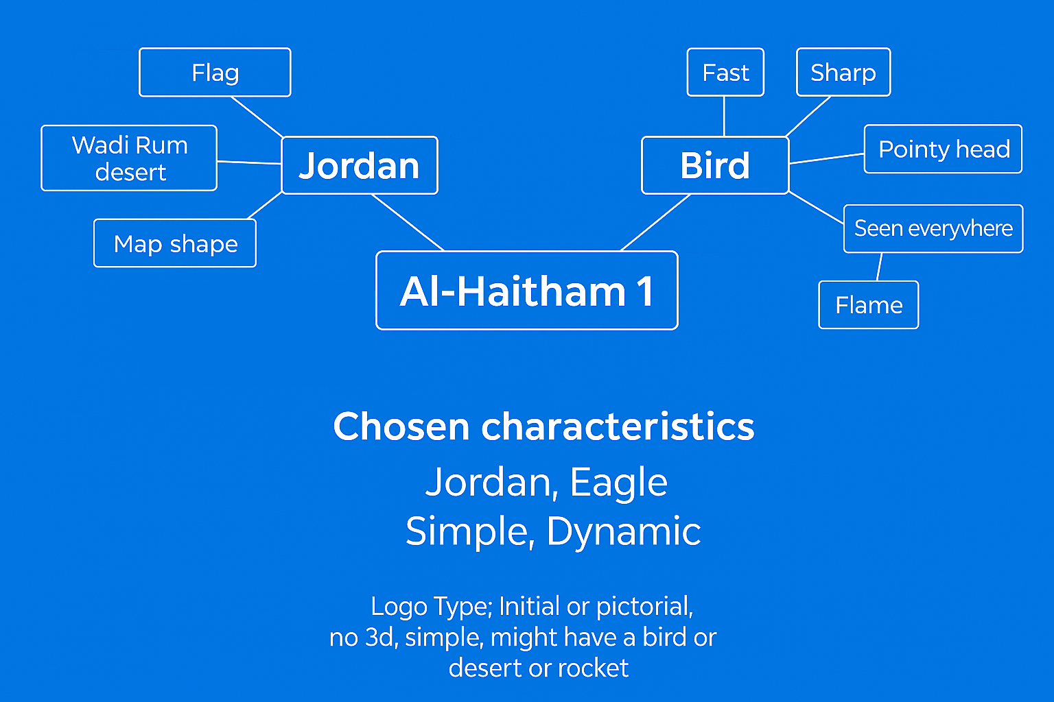
1. Mission Name Brain Storming:
- JORD-X – a modern, tech-sounding name combining Jordan and exploration.
- Al-Haitham-1 – Arabic name for a young eagle, meaningful and authentic. ✅
- Ram Rocket – nod to Wadi Rum, catchy and easy to remember.
2.Idea Gathering:
3 .Photo Gathering
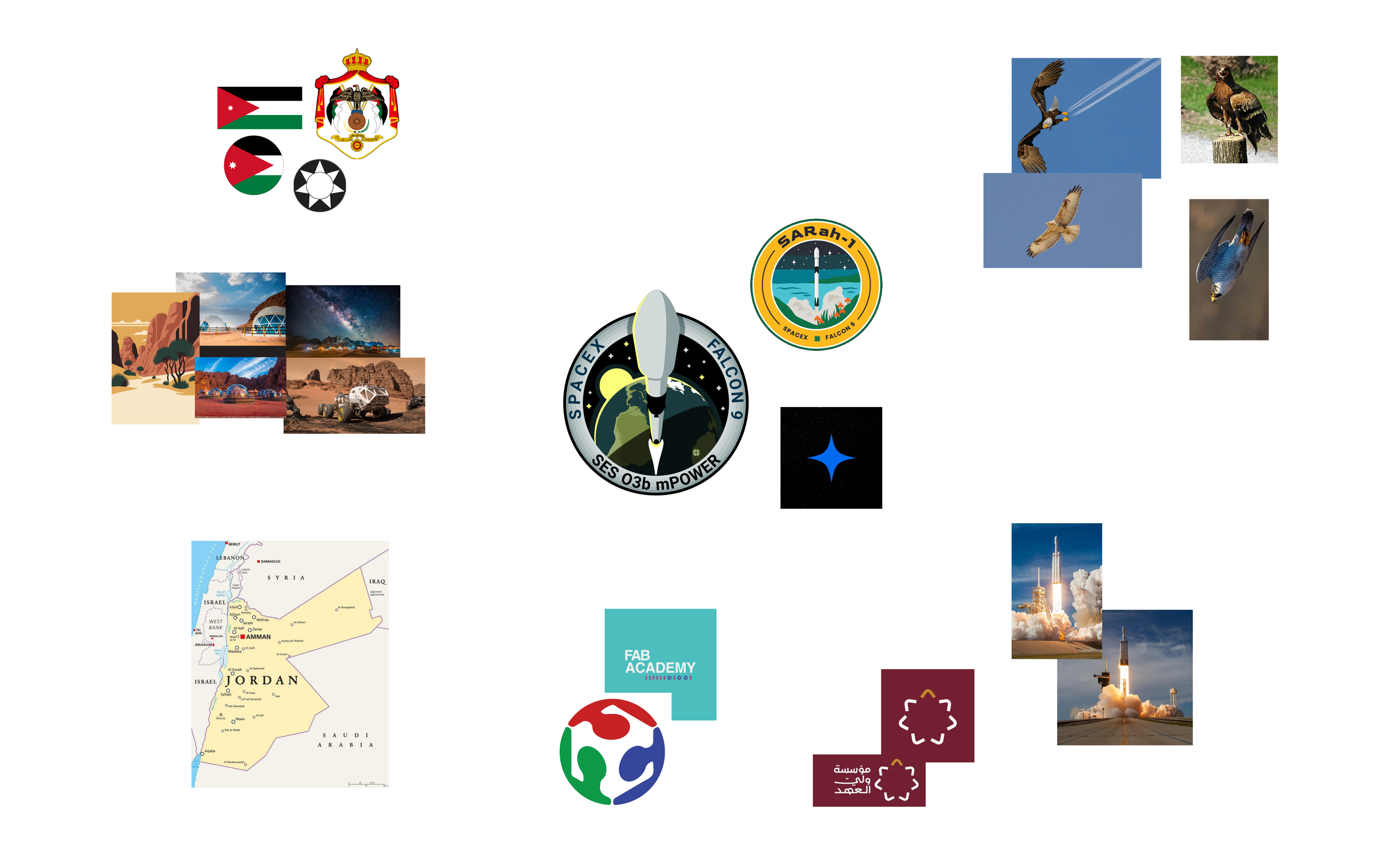
- Jordanian Flag: Proudly included to symbolize the national identity and cultural heritage of Jordan.
- Wadi Rum Desert: Featured in the background to represent the iconic and historic Jordanian landscape.
- Fab Logo (Red, Green, Blue-sky): Chosen to reflect the core colors of the Fab Academy logo, tying the mission to its academic foundation.
- Red Ground Base: A strong red layer under the rocket represents crown prince foundation, strength, and liftoff origin.
- Rocket Flame: Added beneath the rocket to express motion, thrust, and the fiery energy of takeoff.
- Rocket Shape (Jordanian Eagle Inspired): Designed with a sharp and pointy look, reflecting the speed, focus, and pride of the Jordanian eagle.
- White Star: Included from the Jordanian flag to honor its symbolism and connect the mission to the nation.
4 .Chat GPT Ideas (Text to 2D)
I’d like your help designing a mission patch logo. As shown in the reference image I provided, I’ve gathered some inspiration and have a clear vision for the design. I want the patch to reflect Jordan — incorporating the Jordanian flag colors, and ideally, a desert landscape in the center. It would be great to include the map of Jordan in the background, with a rocket launching from it. Around the patch’s border, I’d like the mission name, “Al-Haitham 1,” along with a mention of Fab Academy and the Maker Space I’m working from. I also want to include stars in the background to represent space. If possible, I’d love for the rocket to appear as if it’s launching out of the patch in a 3D style, with visible thrust flames to enhance the dynamic look.

5 .Logo Design:

v 0.1 

v0.2 
Open Rocket (Simulation)
Simulation v1
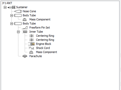
To achieve this, we followed a procedure where each rocket part was individually fabricated, weighed, and then added to the simulation model. Only after feeding all component weights into OpenRocket could we analyze performance and make informed design decisions.
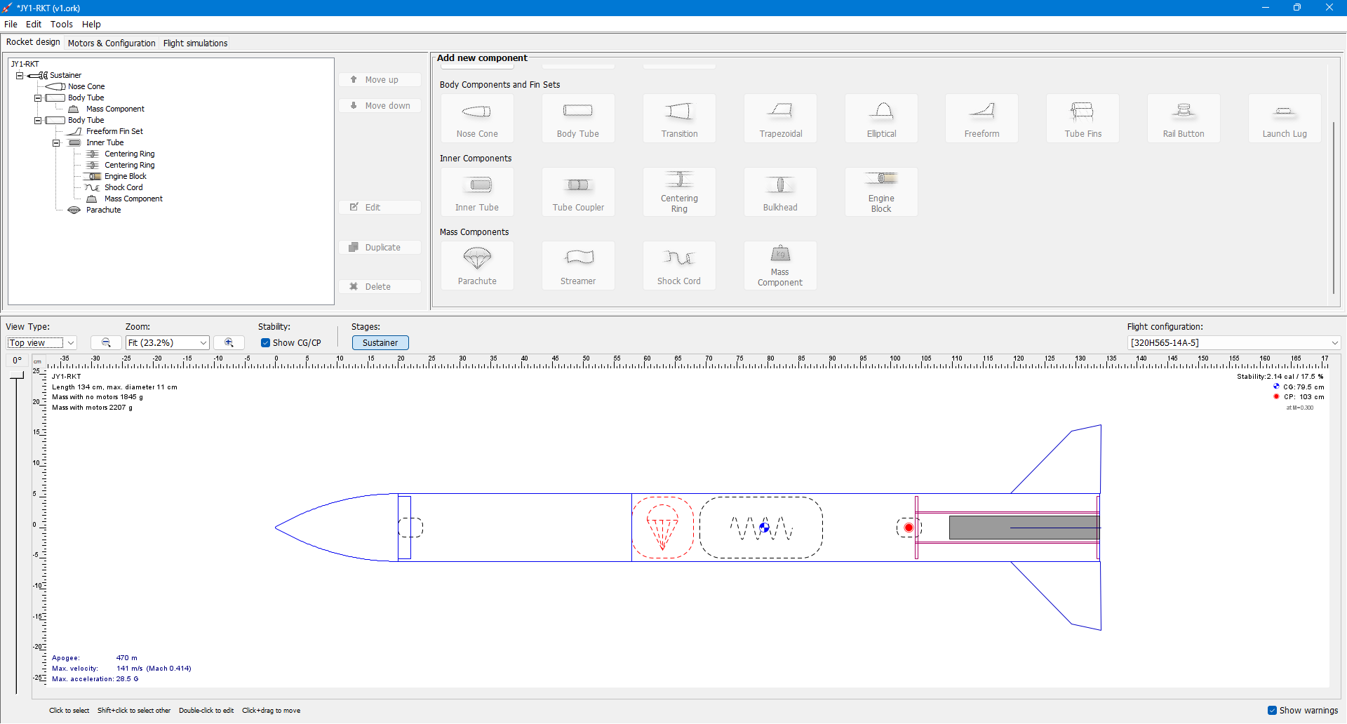
After being introduced to the OpenRocket simulation program, I realized the importance of maintaining a precise workflow between fabrication and simulation. In a rocket lab, it’s critical to input the exact weight of each component to ensure accurate flight predictions and stability.
So far, we have incorporated several key parts into the system, excluding the main body tubes. The rocket design includes two tubes (76 cm and 38 cm) forming a one-stage configuration, a center ring, a motor mount, and a shock cord that connects the two tubes. Additionally, a shock cord hook is used to securely tie all components together.
Each part was designed, fabricated, and documented separately before entering its specifications into the simulation. This process helped us verify structural and flight accuracy at every step.
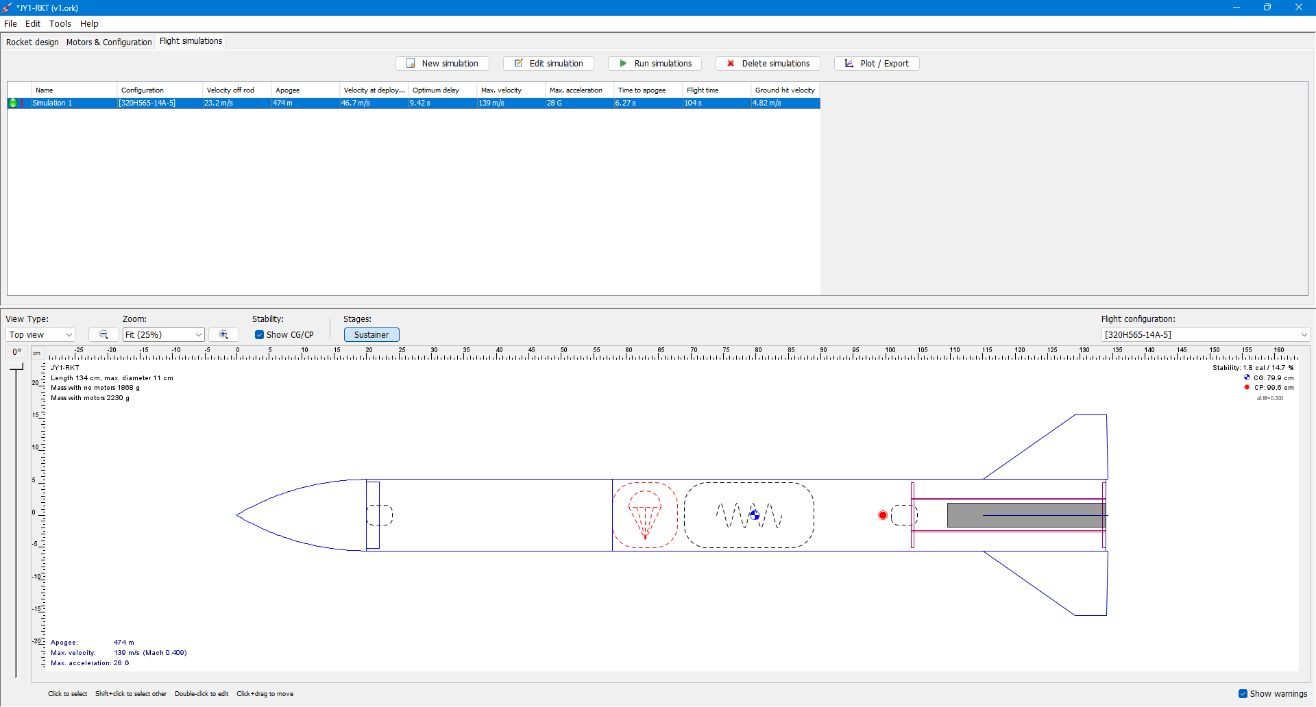
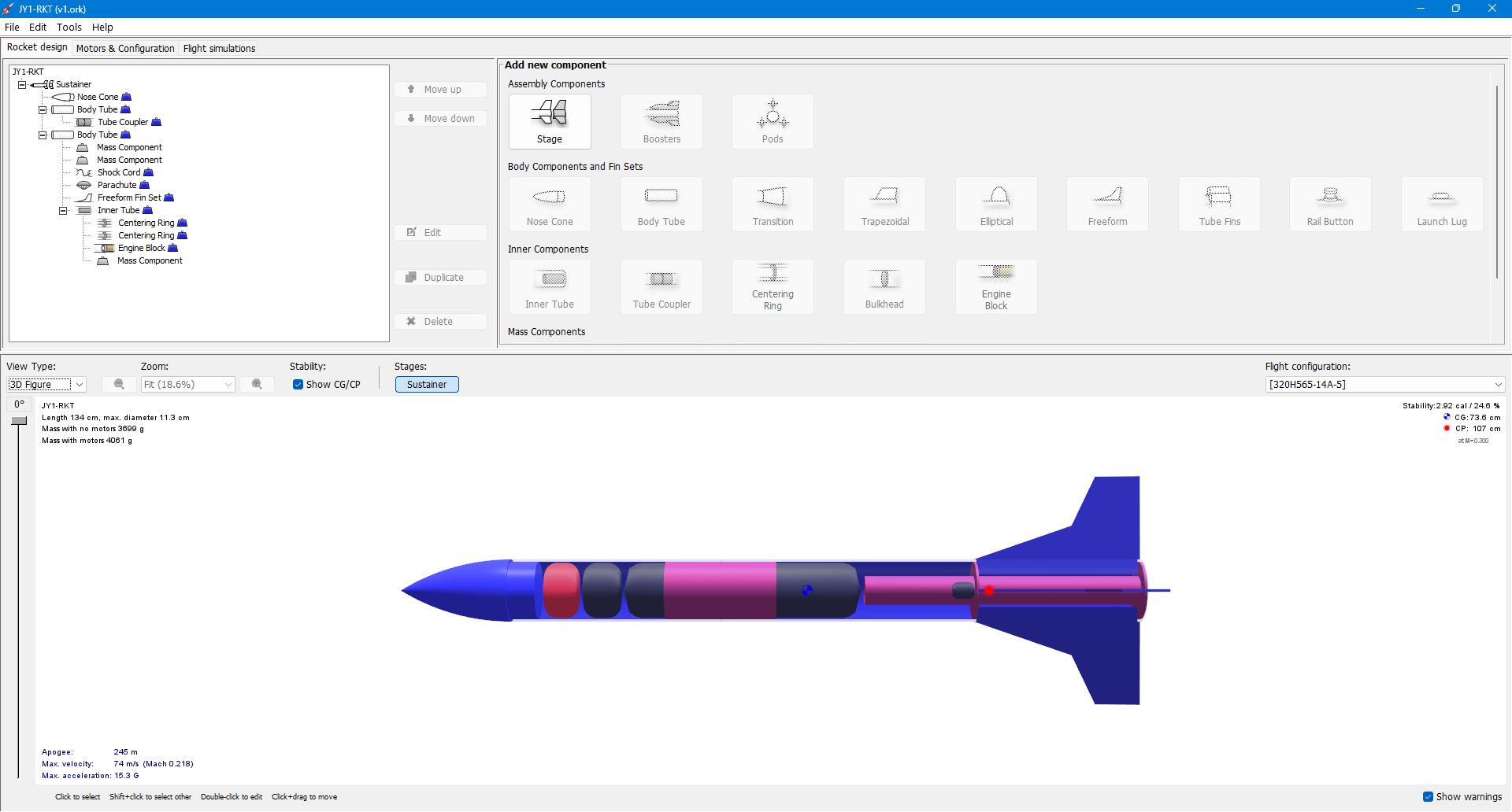
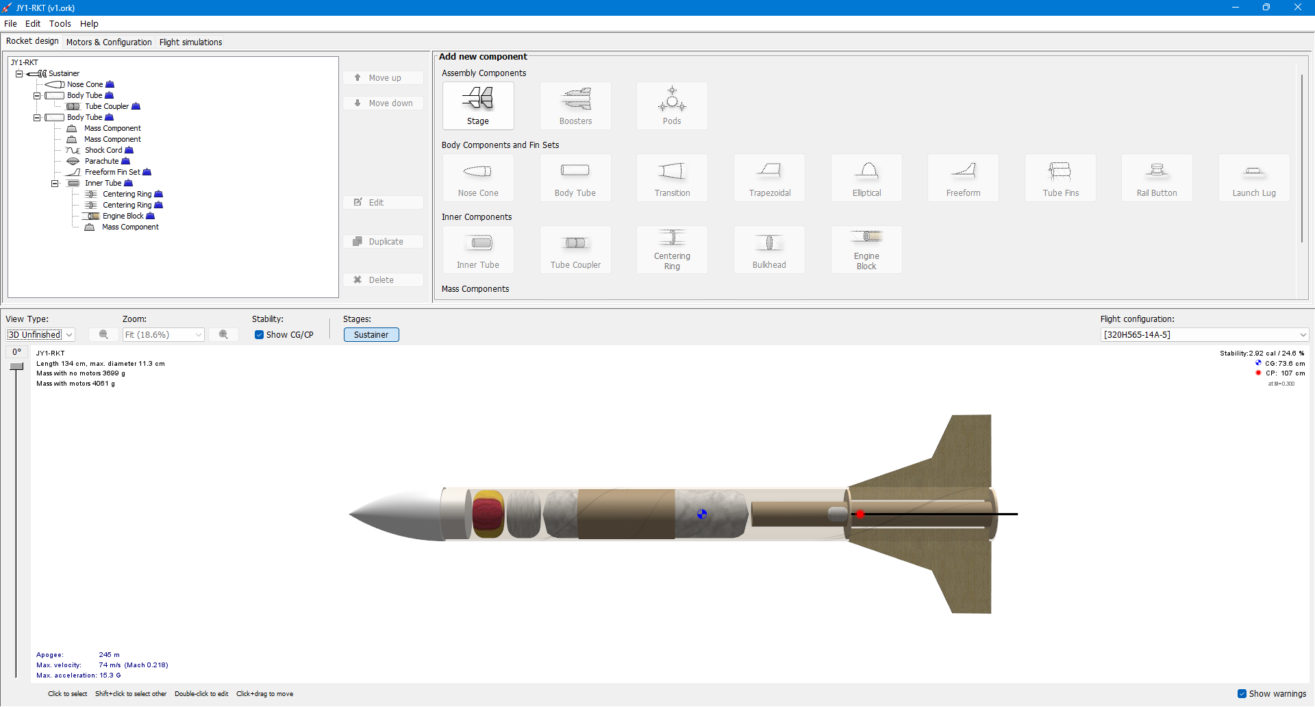
Simulation v2
In this second simulation using OpenRocket, I carefully measured each component of the rocket and replicated them in the software to ensure the virtual model closely matches the real-world build. After validating that all physical parameters align correctly, I achieved a stability margin of
2.92 calibers, which is ideal—well within the standard range for a Level 1 (L1) rocket, typically between 2.0 and 3.0. Reaching this level of stability was one of my initial goals, and I'm glad to have met it successfully.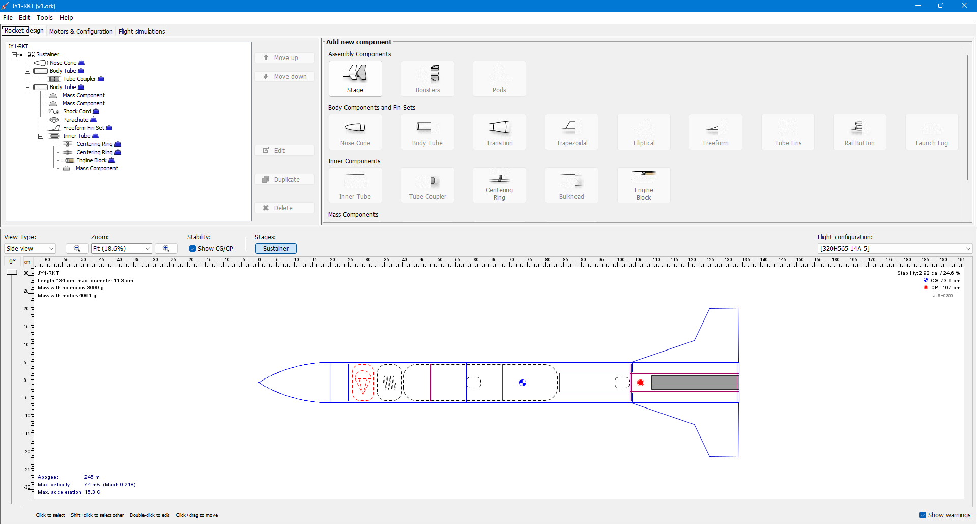
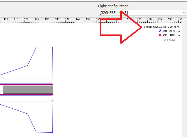
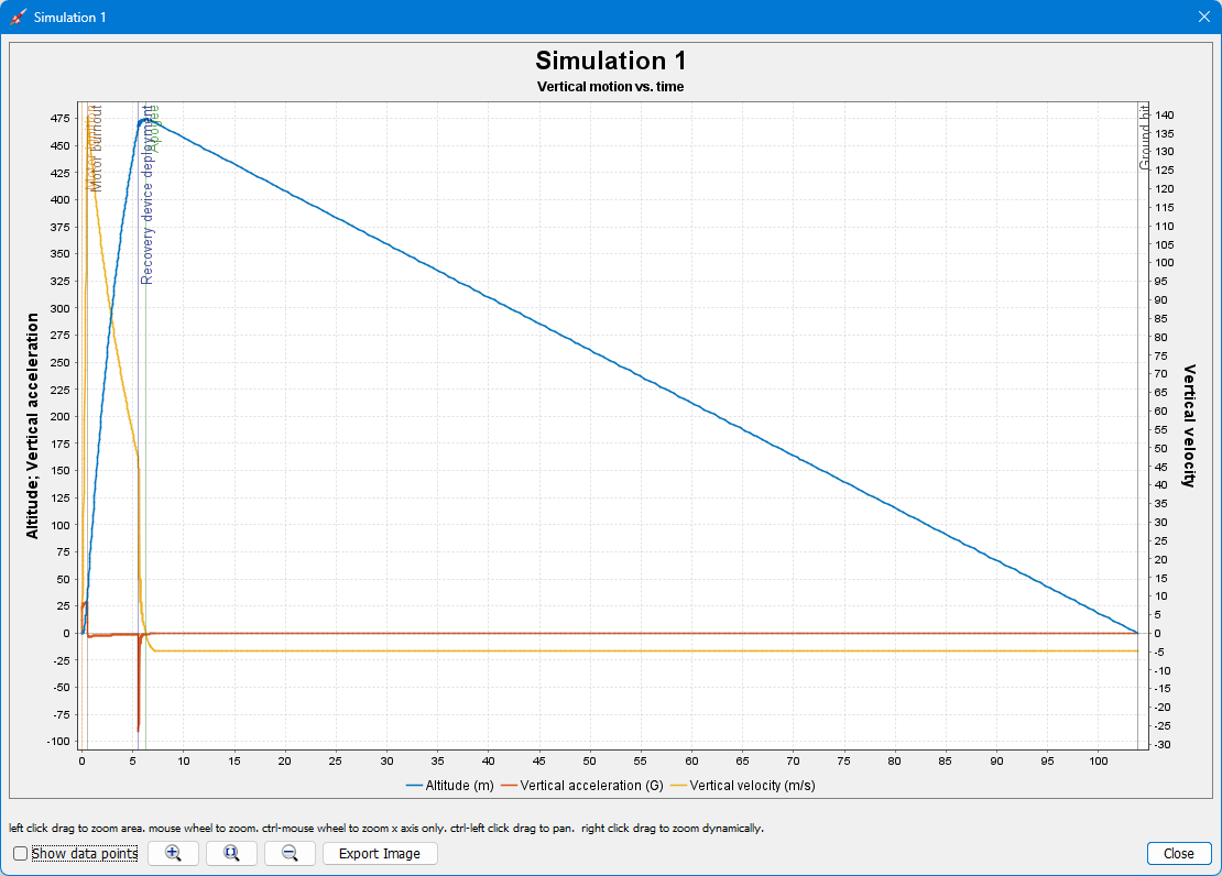
The simulation results show that the rocket is expected to reach a
maximum apogee of 245 meters, with a total flight time of approximately 43 seconds. Additionally, the graphs included demonstrate the maximum velocity and acceleration throughout the flight, providing a clear overview of the rocket's expected performance.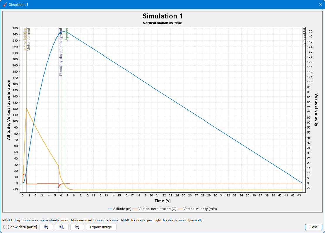
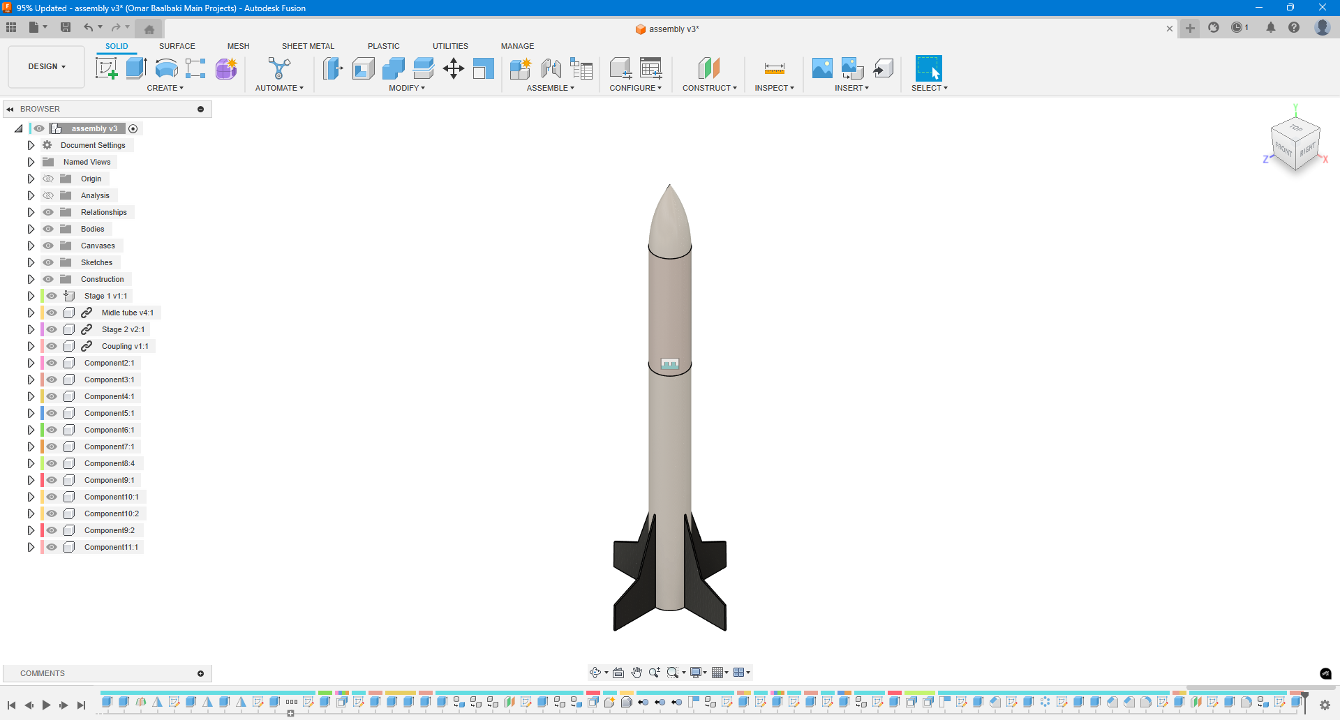
3D CAD
3D CAD
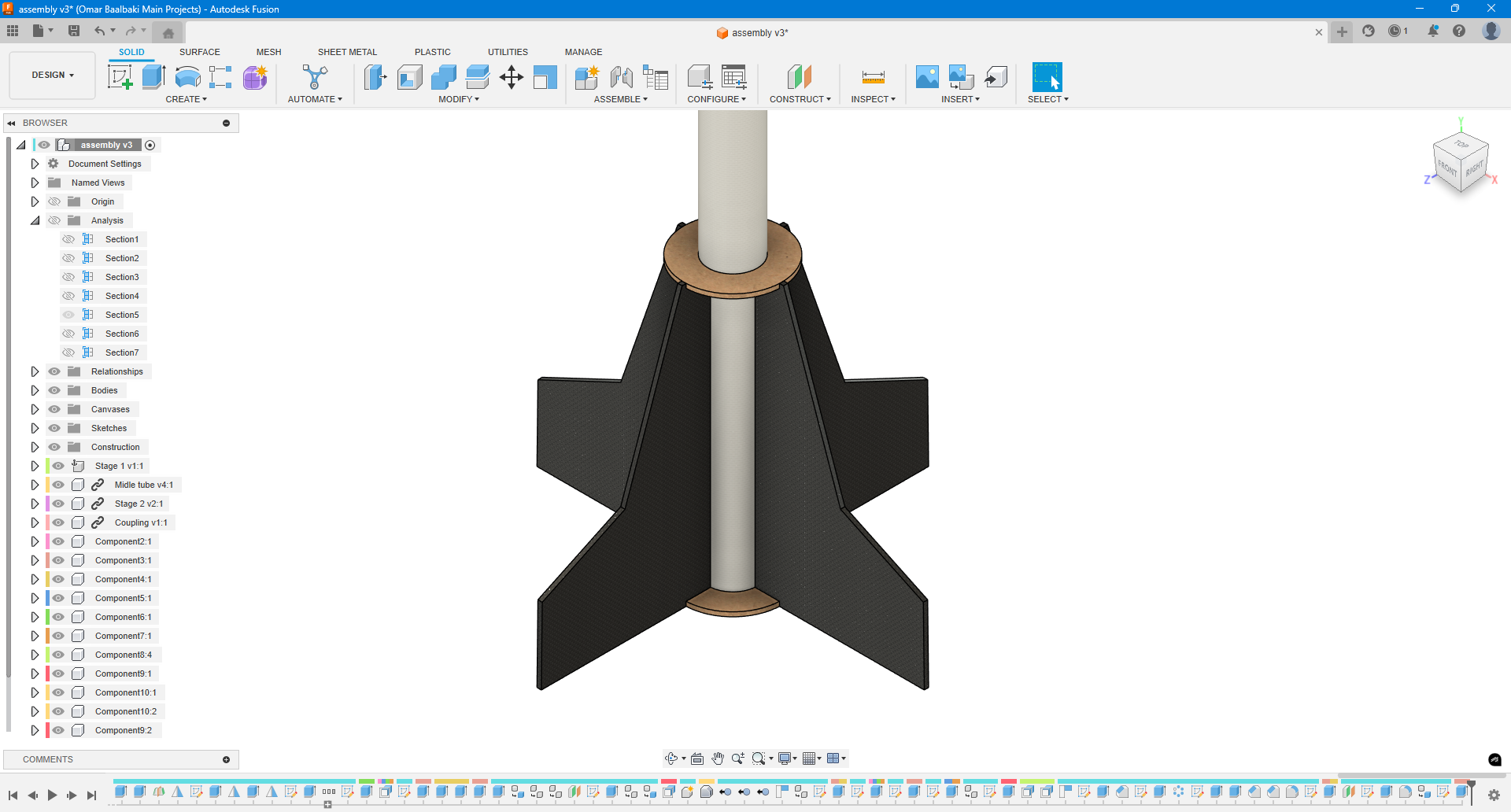
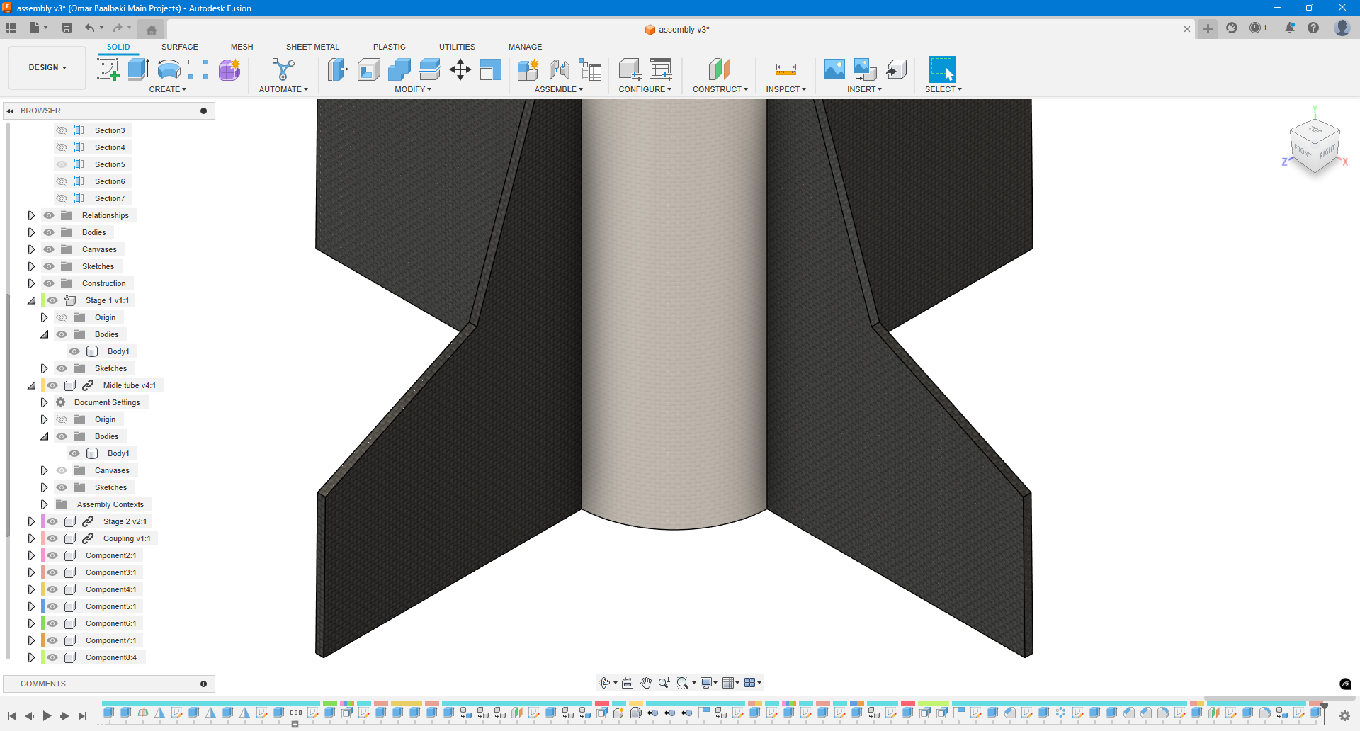
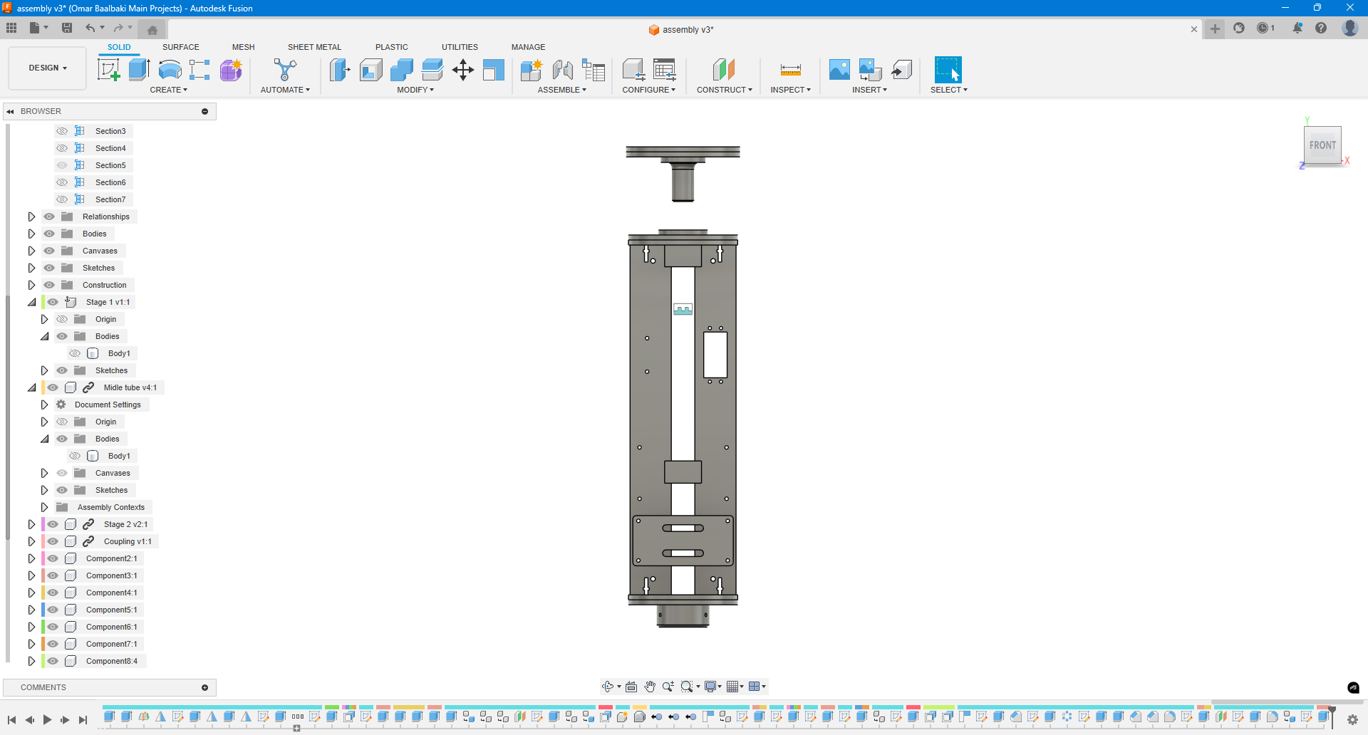
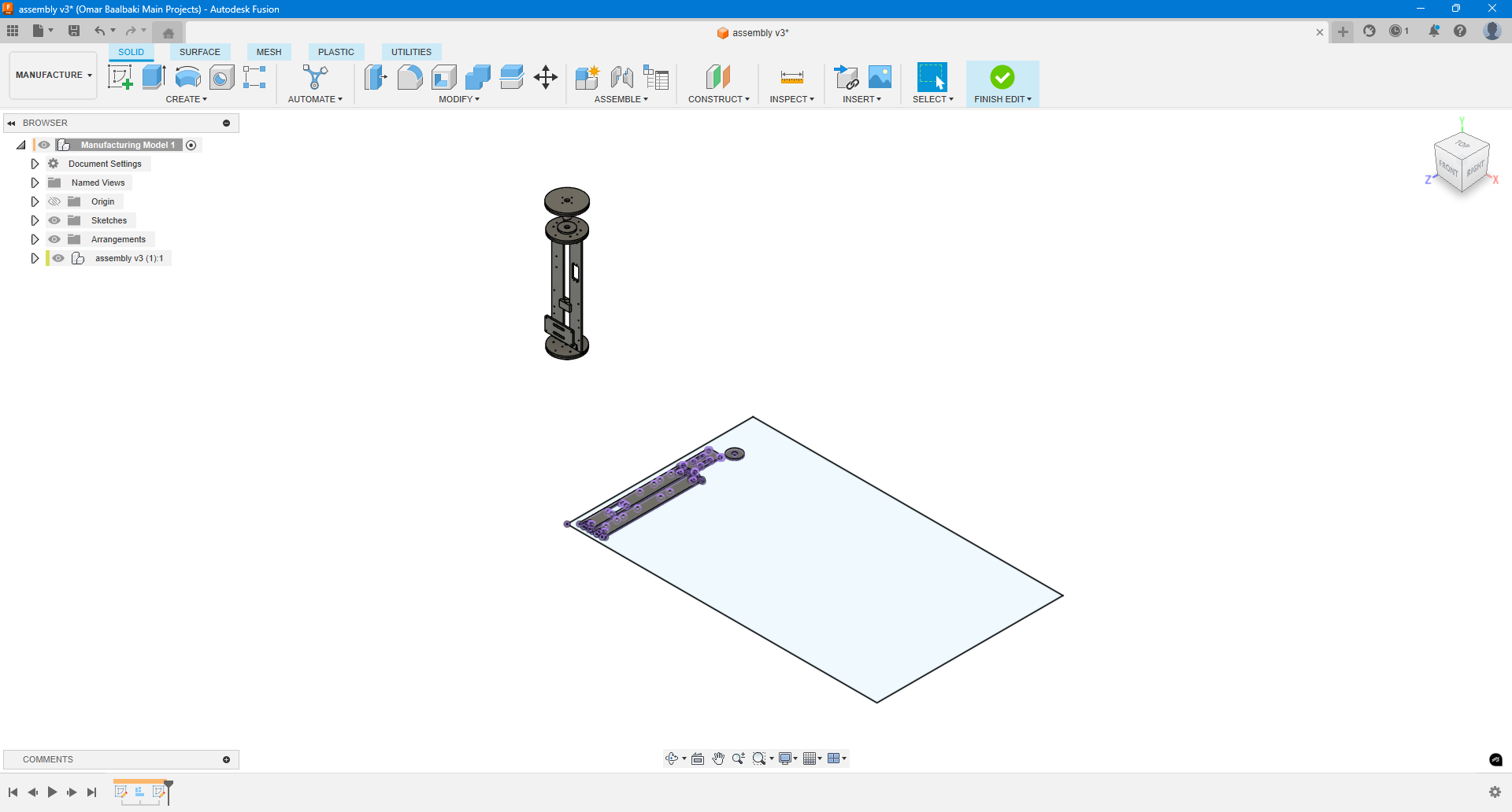
For this part of the project, I used
Fusion 360 to fully design the rocket and its components. The design process included not only modeling the structure but also utilizing the Manufacture workspace in Fusion to export several parts as DXF files for laser cutting, as shown in the photos.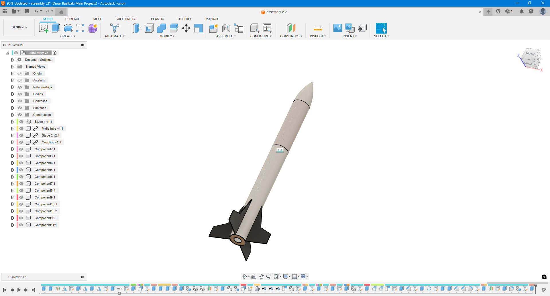
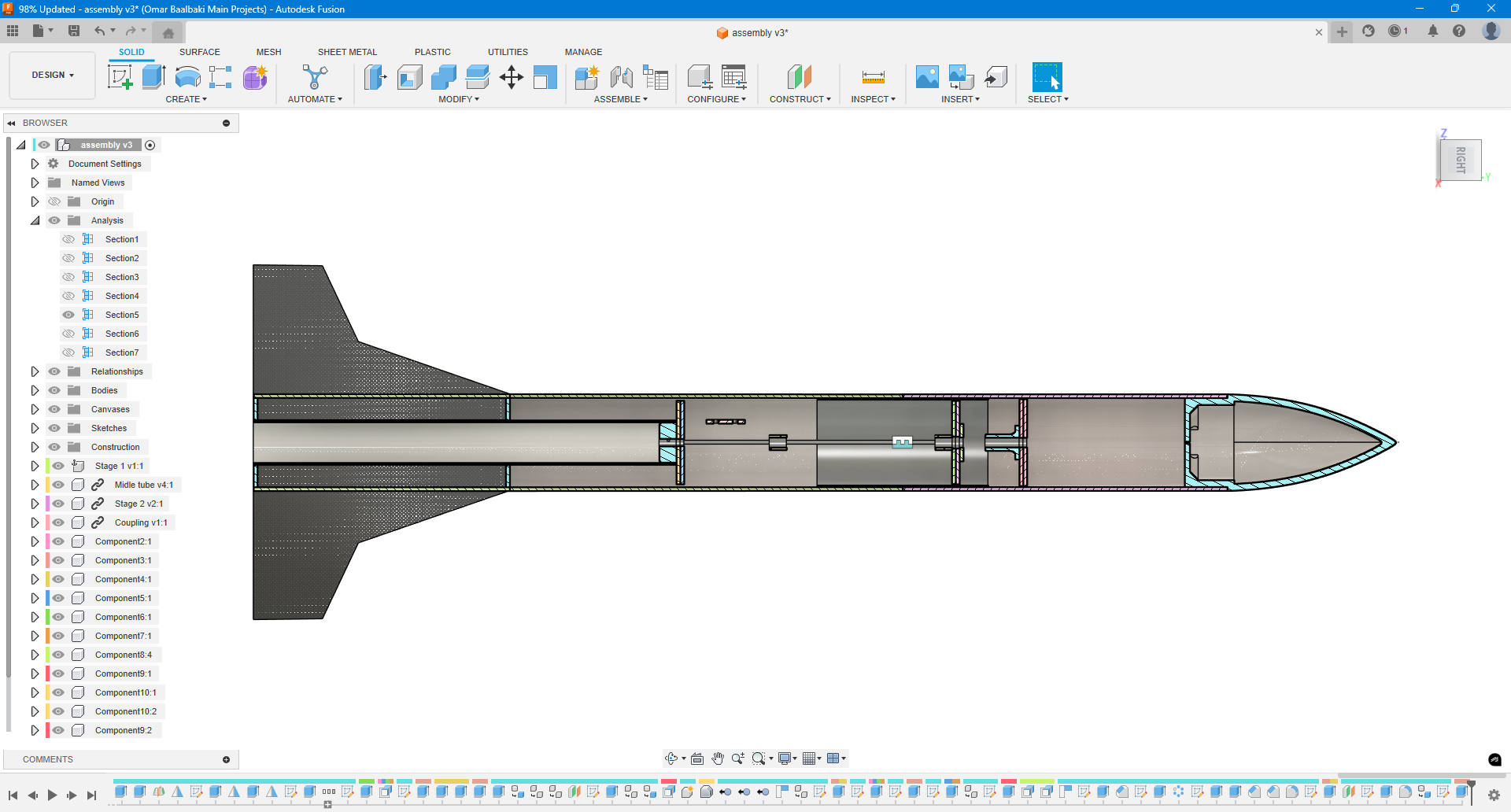
To ensure alignment and accuracy, I performed multiple
section analyses within Fusion, especially to verify that the design matches the dimensions and parameters defined earlier in the OpenRocket simulations. Some structural elements were designed specifically for alignment purposes, such as the fin support layers.
One key example is the
three-layered MDF fin alignment system. I used 3 mm MDF sheets to build an alignment jig that guarantees the fins are positioned precisely at 90° angles relative to each other. This ensured perfect orientation and eliminated any risk of misalignment during assembly.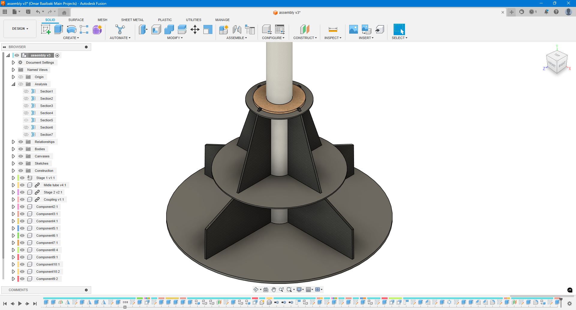
In addition to laser-cutting, I
3D printed certain parts—notably a very thin single-wall mold piece. This mold was used to trace accurate cutting lines onto the fiberglass tube, guiding the production of the fins so they would fit perfectly and align correctly with the rocket body.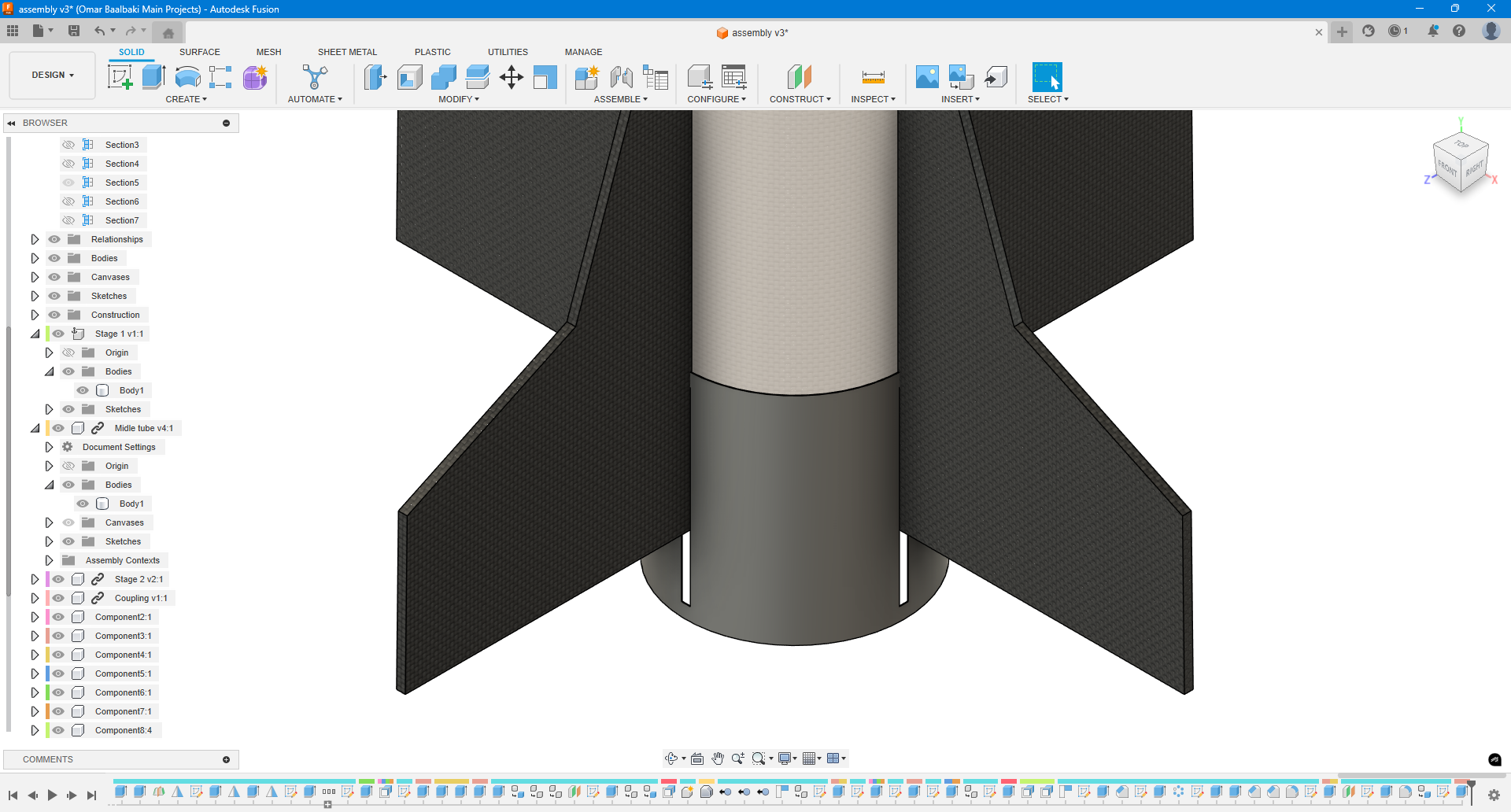
Another critical part of the design phase was the parachute deployment mechanism, which went through several design iterations. Fusion 360 allowed me to carefully model and refine the mechanism before fabrication. Once finalized, I exported the 2D profiles for laser cutting, converting them into DXF files for accurate and efficient manufacturing.
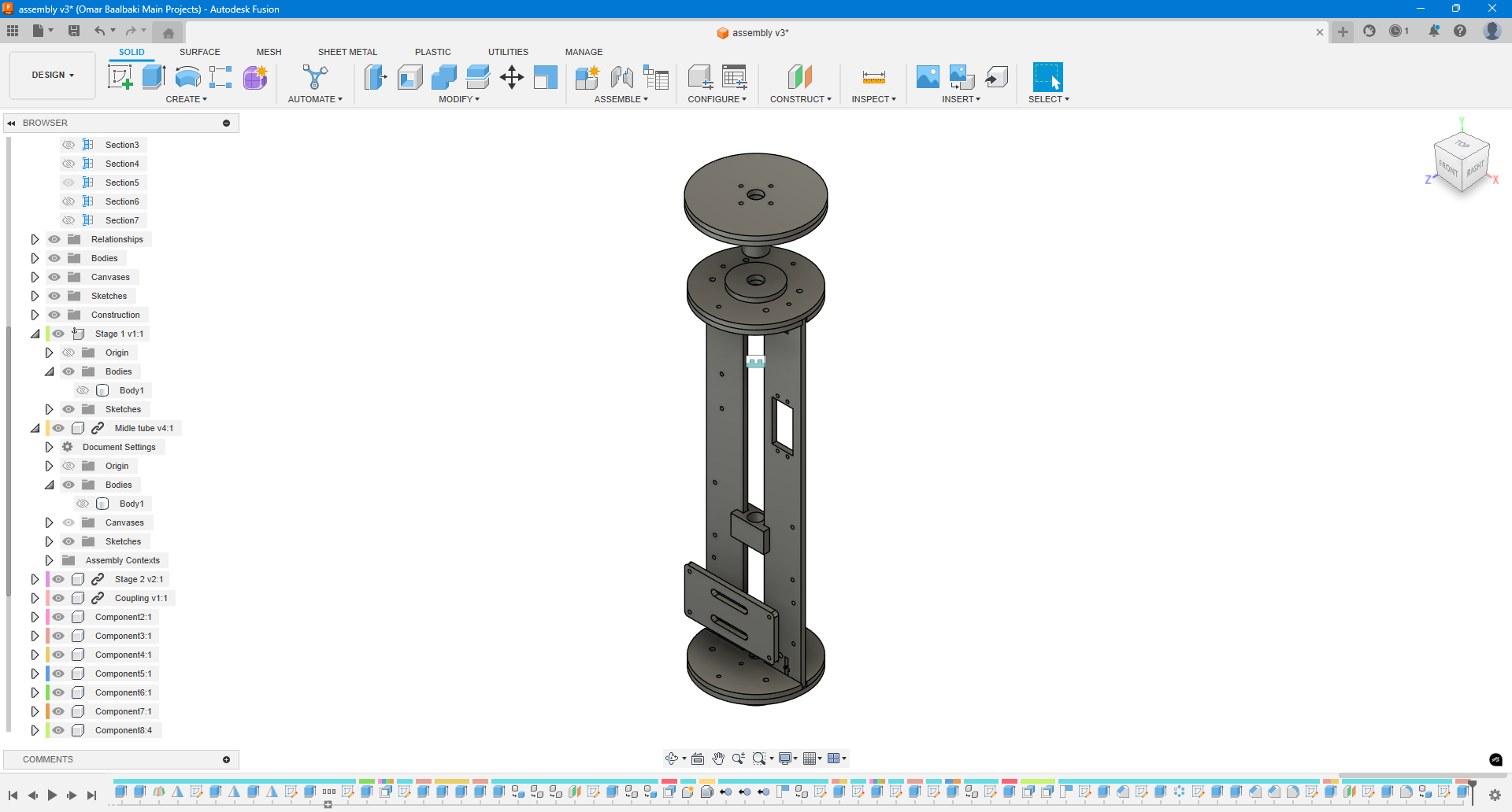
Overall, Fusion 360 played a vital role not only in the design process but also in preparing the project for digital fabrication, ensuring both functionality and precision across all physical components.
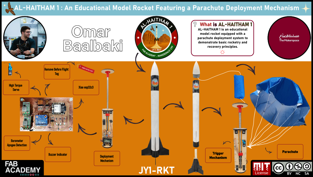
Poster
Poster
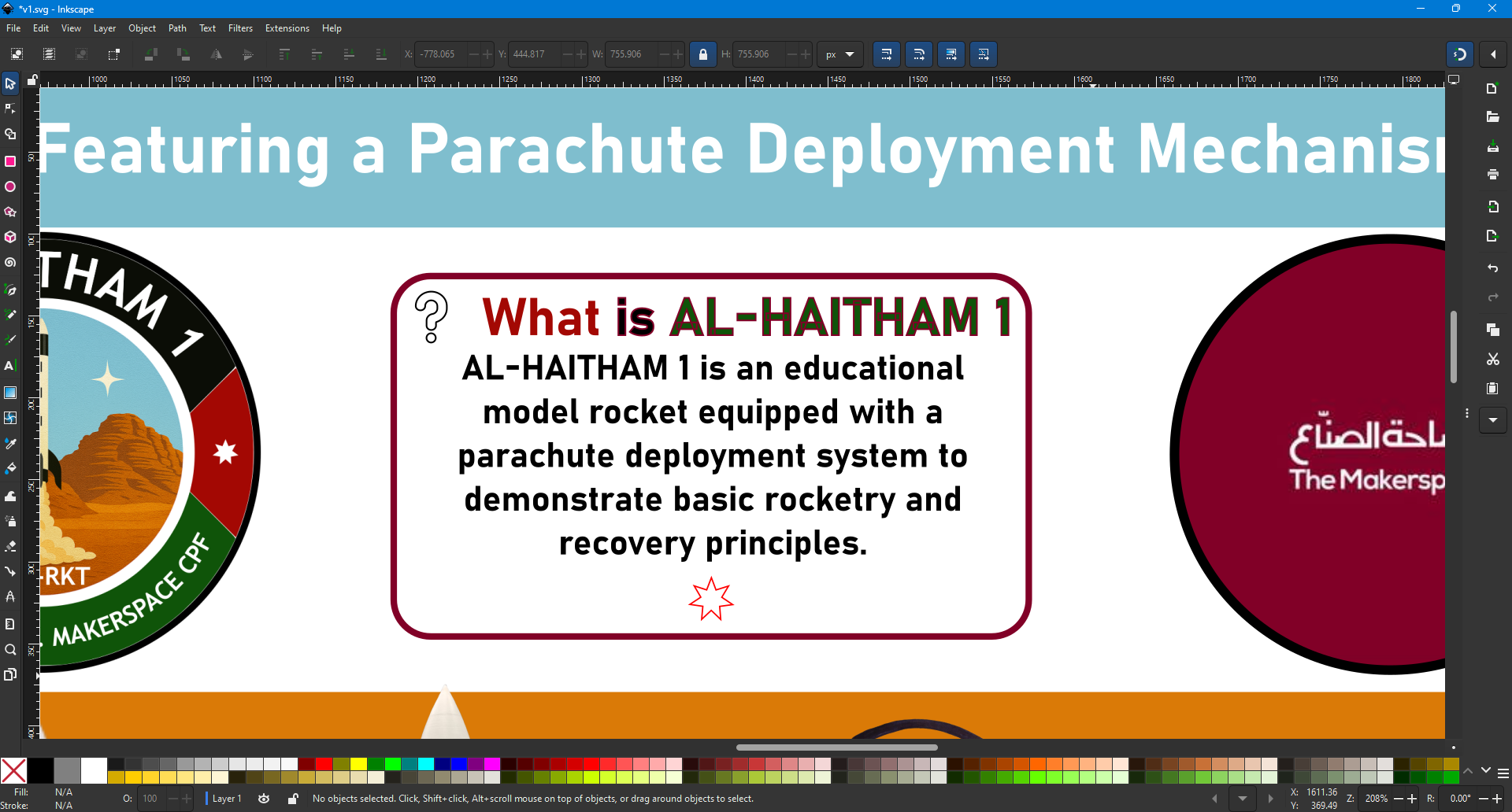
For the presentation poster, I used Inkscape, a tool we explored during the second week of Fab Academy, which allowed me to work entirely with vector-based graphics.
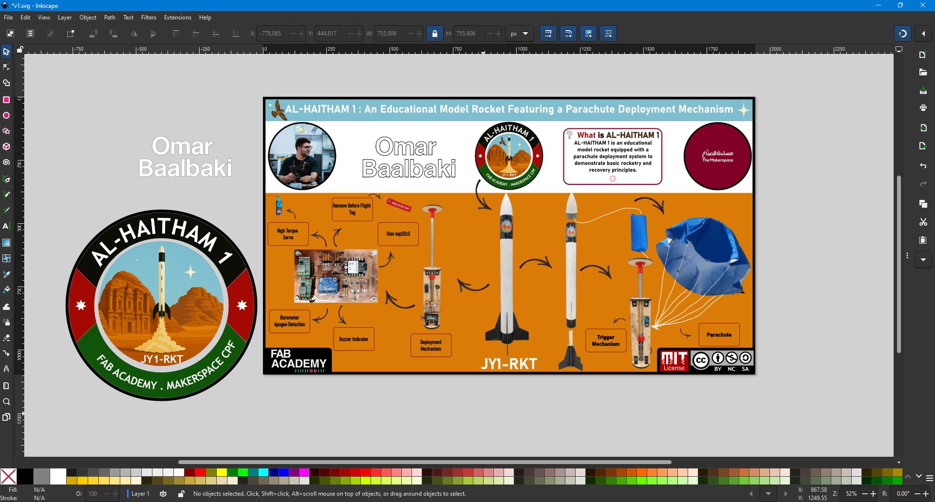
The poster design incorporates several visual metaphors to add symbolic meaning. In the “What is Alhaitham-1?” section, the title colors reflect the Jordanian flag:
- “What” appears in red,
- “Is” in black,
- “Alhaitham” in green.
These choices are deliberate, tying the project to national identity and pride. Below that section, I included the Jordanian flag’s iconic star, subtly reinforcing the theme.
If you look closely, you’ll also notice that the box containing the description is shaded in the dark red used by the Crown Prince Foundation. This color choice represents the support and guidance I received throughout the project, highlighting their role in helping me navigate the journey and fulfill my vision.
Week 3: Laser the fins + parachute
Laser the fins
Laser the fins
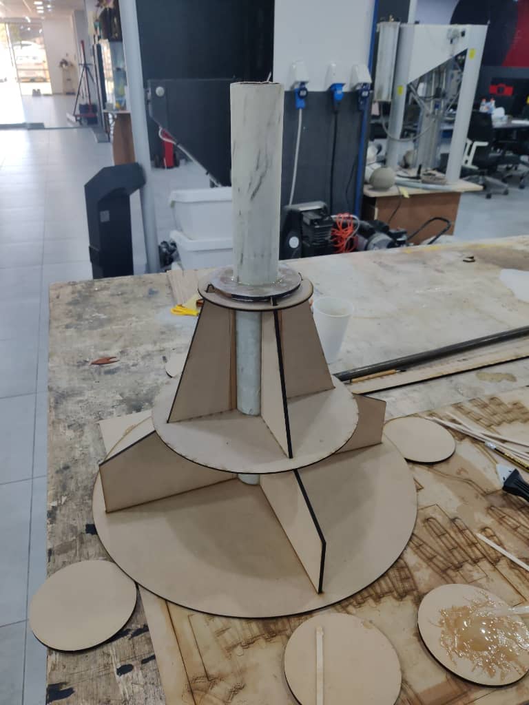
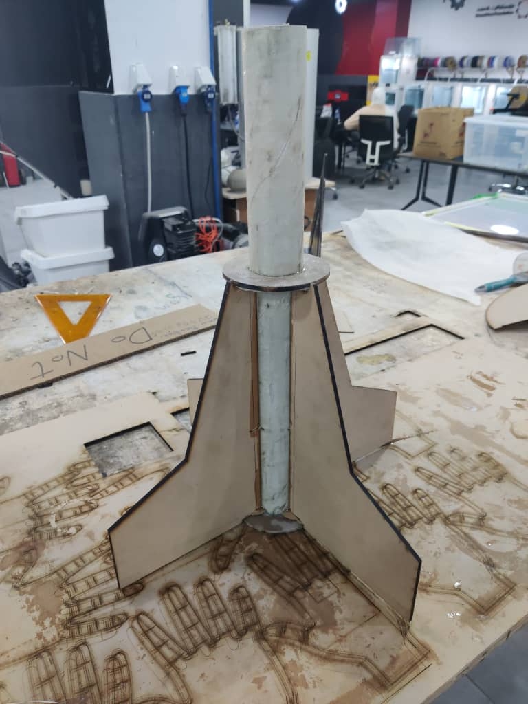
To fabricate the rocket fins, I started by exporting the fin design from Fusion 360 and cutting them out of 4.5mm MDF using a laser cutter.
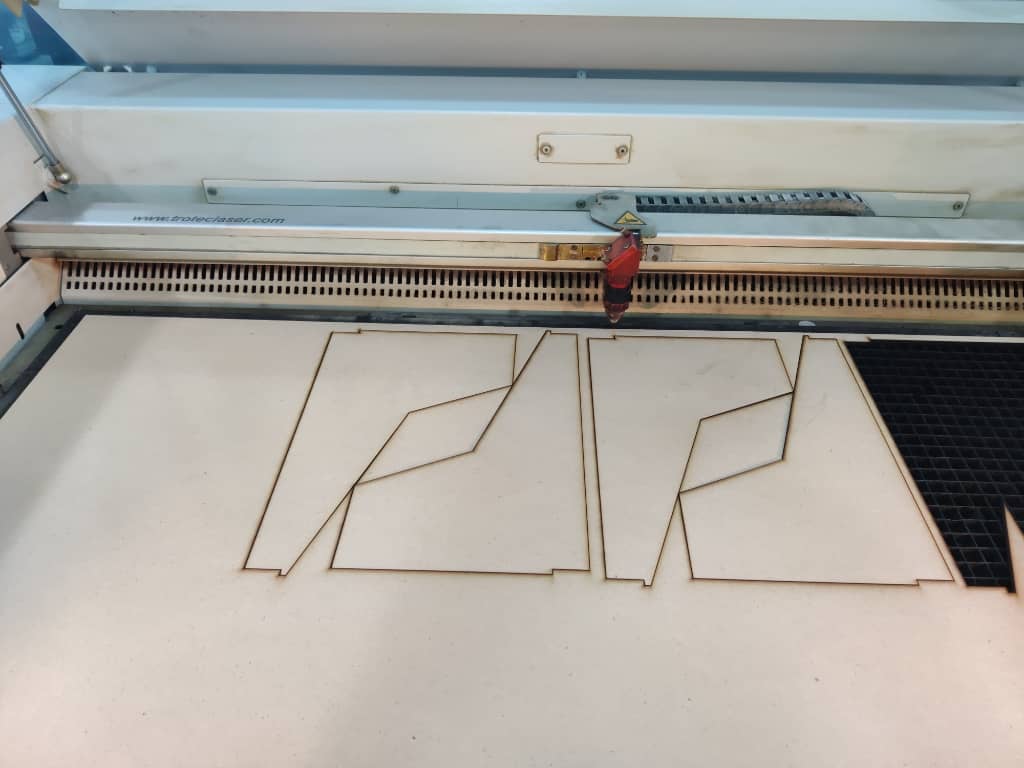
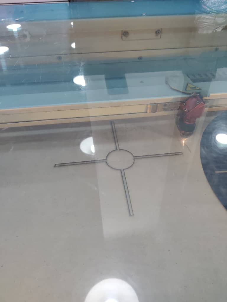
After cutting, I used a custom alignment guide—previously designed and also laser-cut—to position the fins correctly around the fiberglass tube. This guide helped ensure each fin was placed at the correct angle and evenly spaced at 90° intervals.
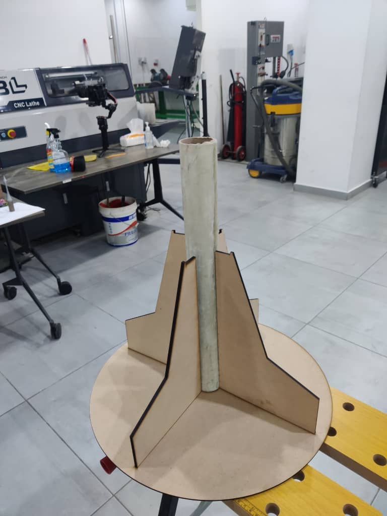
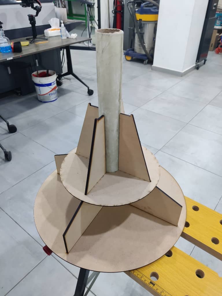
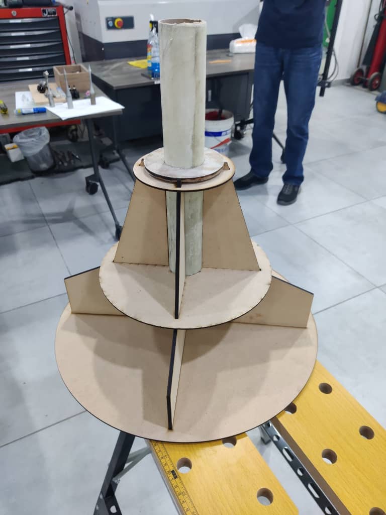
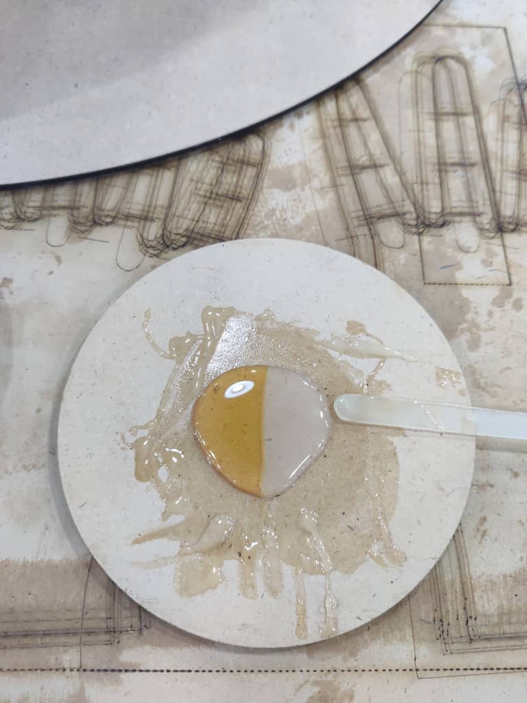
Once everything was positioned and the angles were double-checked, I prepared and applied a two-part epoxy adhesive to bond the fins to the tube. The epoxy was allowed to cure for 24 hours. After curing, I carefully removed the alignment guide disks. This process resulted in a precise and durable tail section for the rocket, with well-aligned fins ready for aerodynamic testing.
parachute
parachute
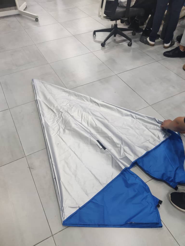
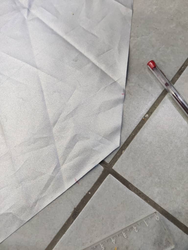
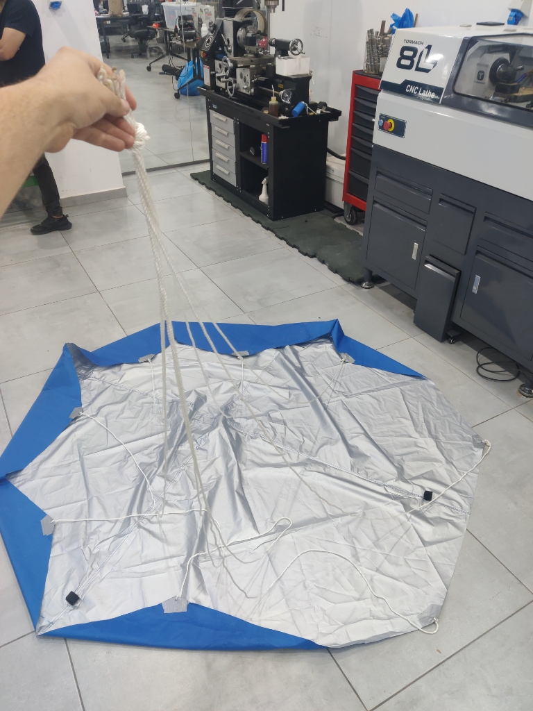
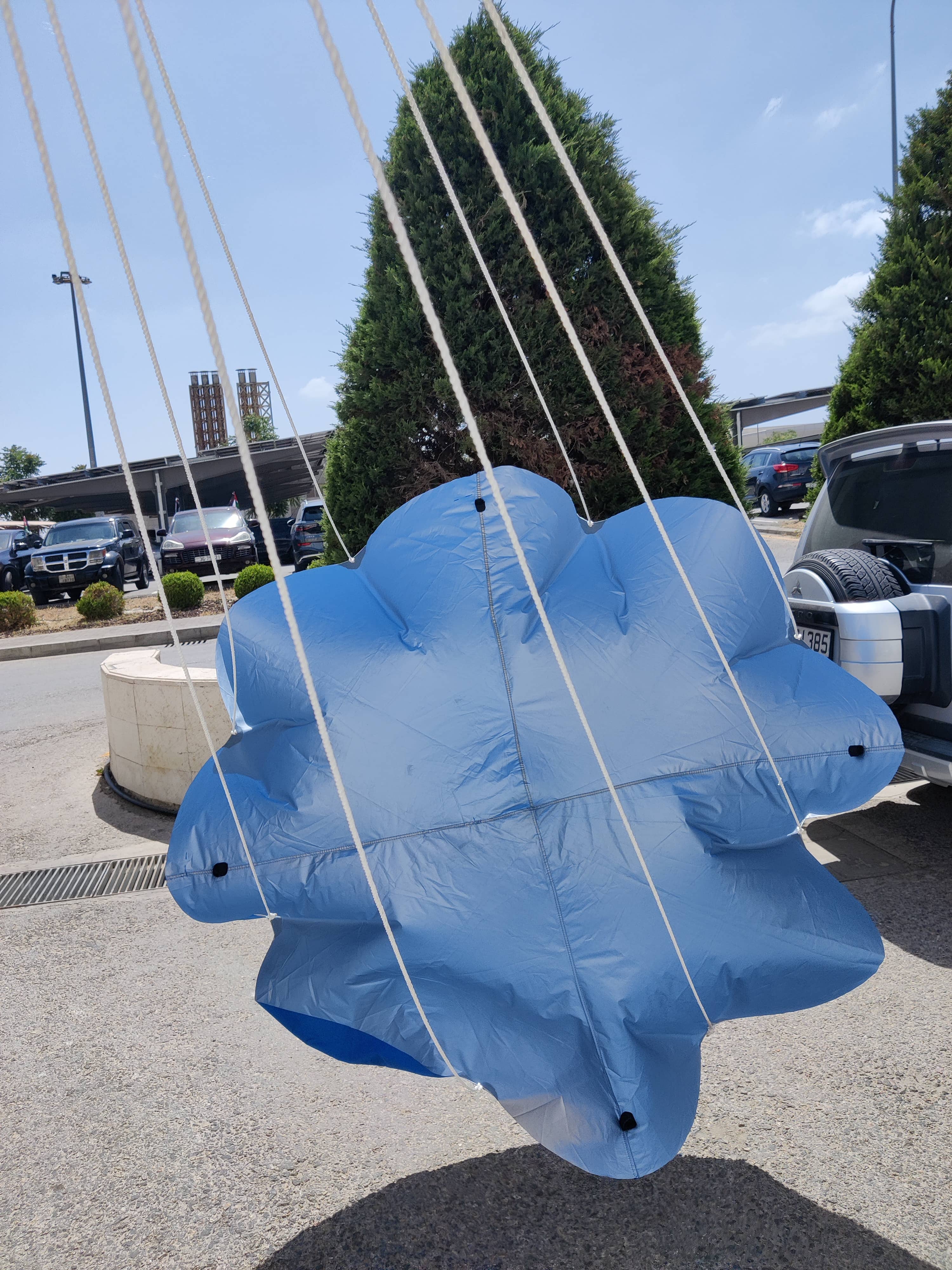
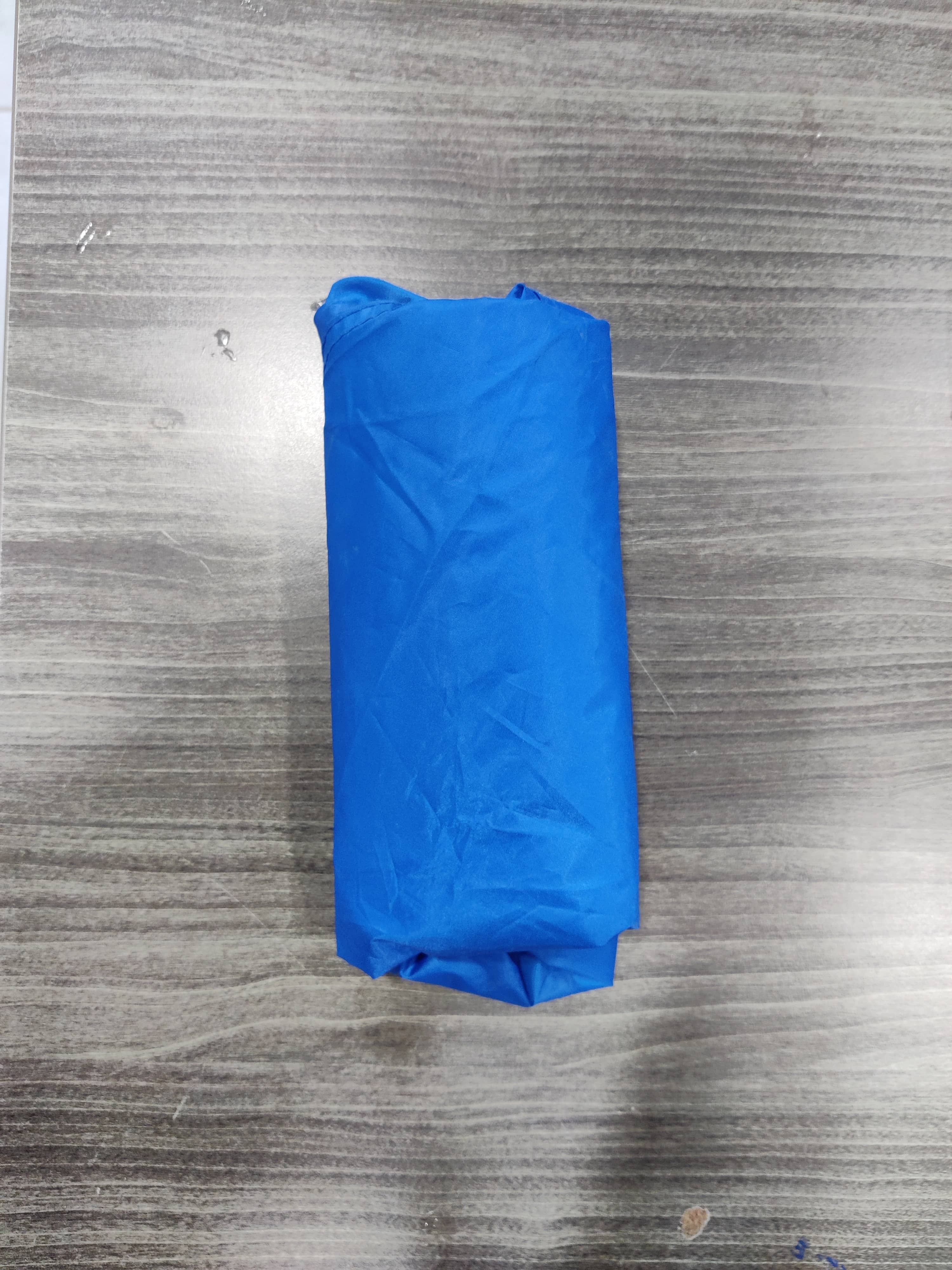
When it came to building the parachute, I explored several materials and methods before realizing that I had an old camping tent made of lightweight, breathable fabric—ideal for parachute use. After confirming that the fabric allowed air to pass through, I decided to repurpose it.
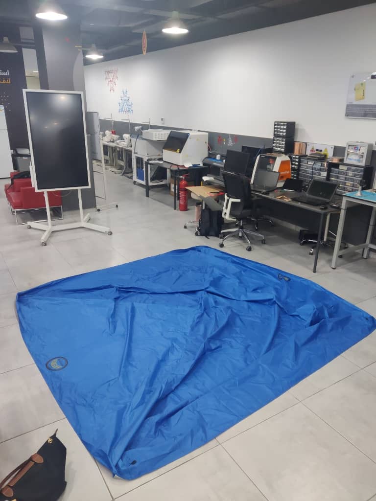
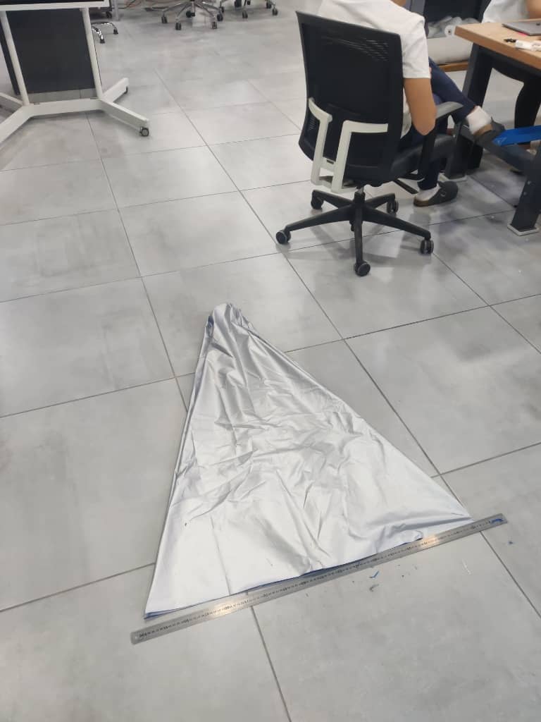
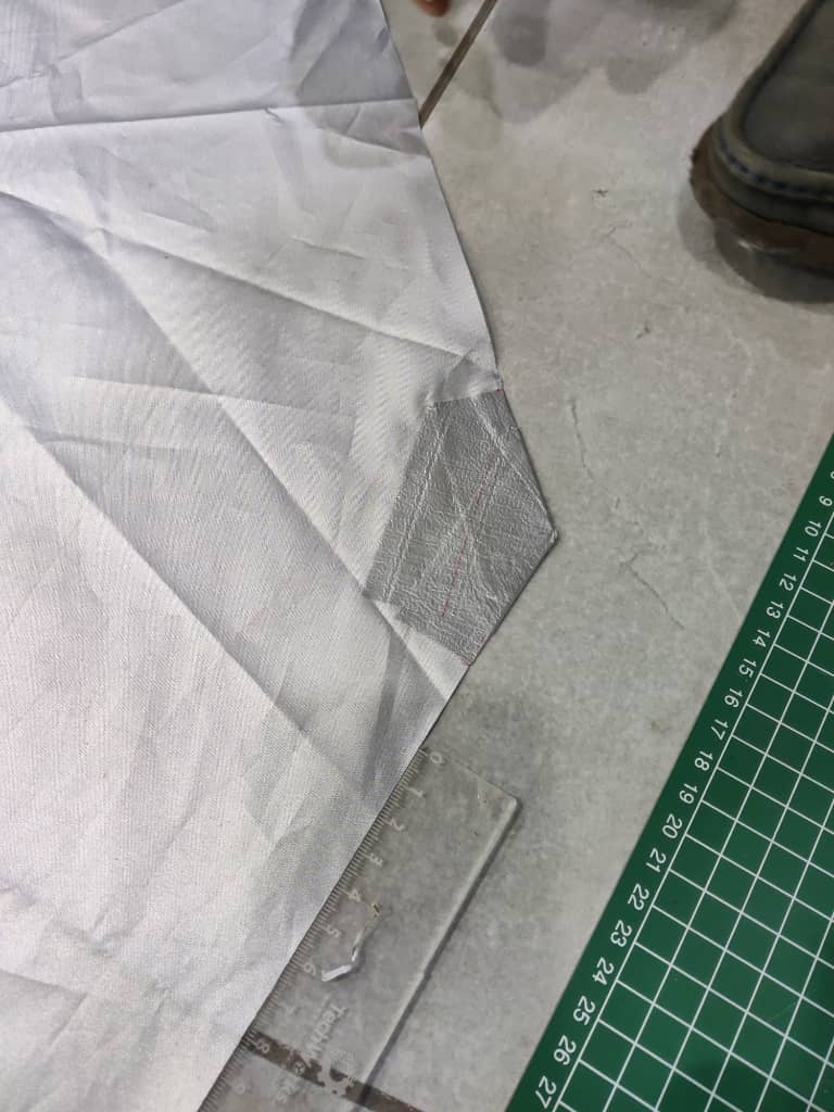
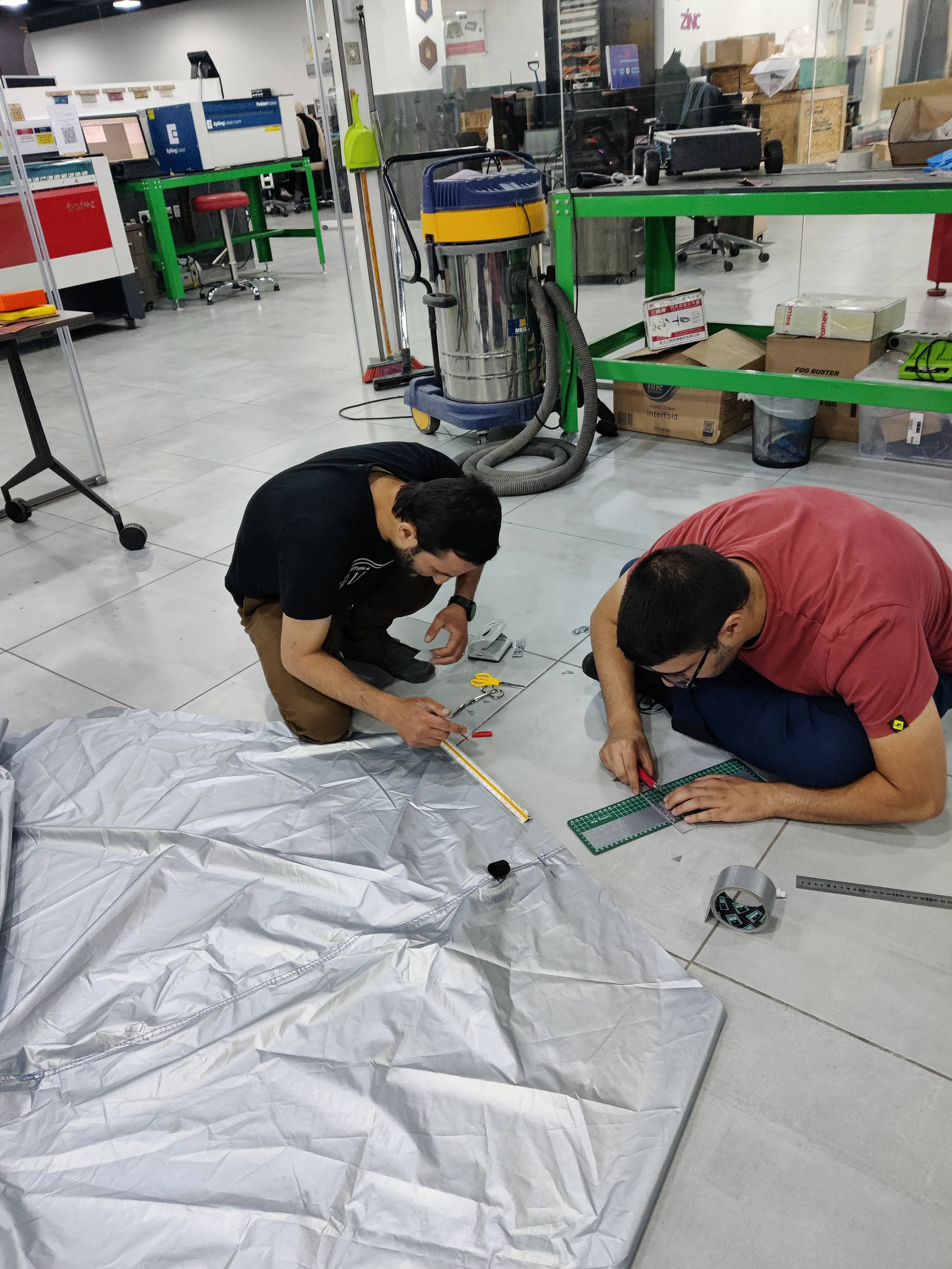
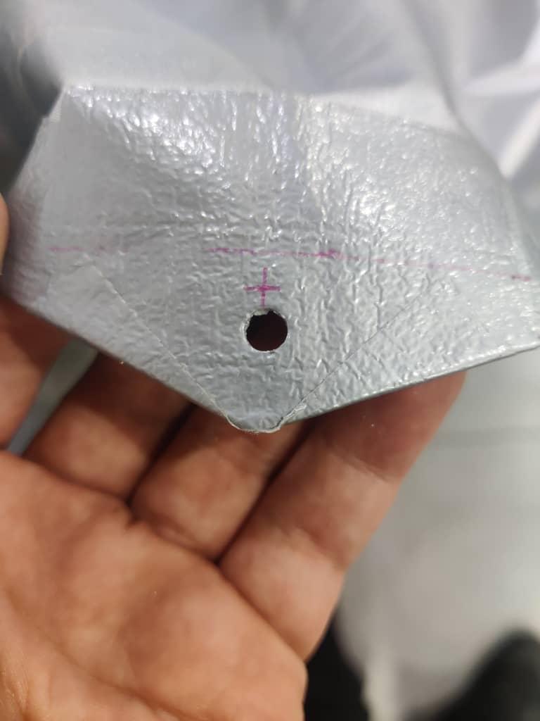
Inspired by origami folding techniques from my childhood, I designed the parachute to form an octagonal shape with eight symmetrical edges. With help from a friend, we carefully measured and marked the pattern using a long ruler, then used a precision blade to cut the fabric accordingly.
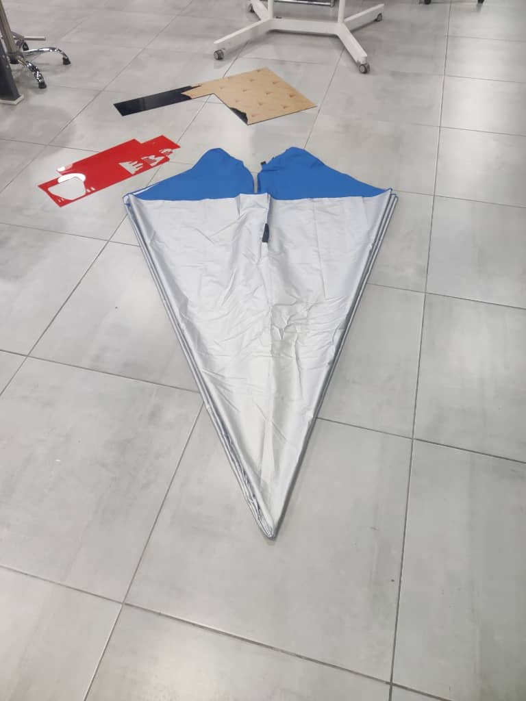
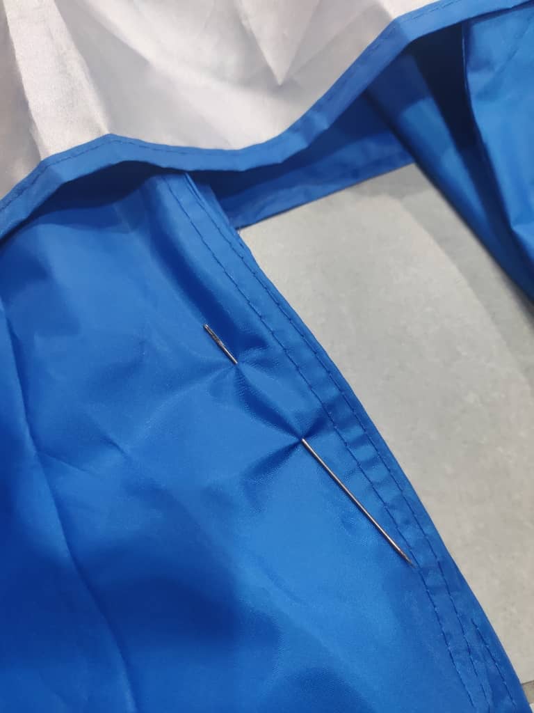
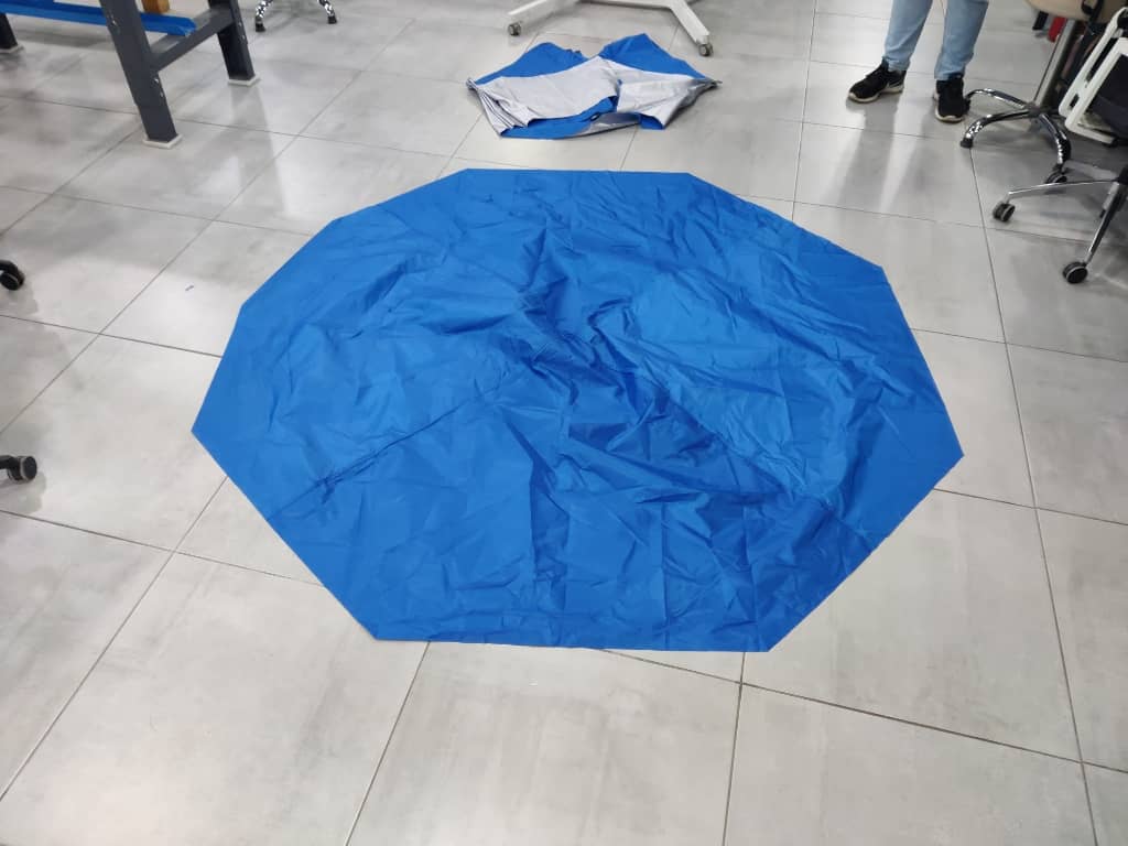
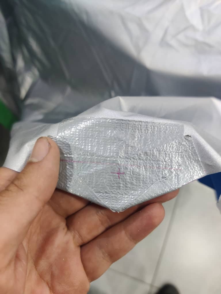
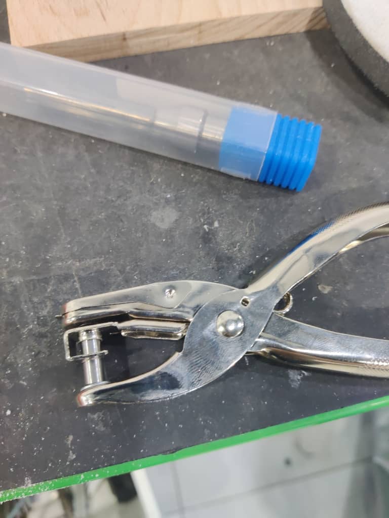
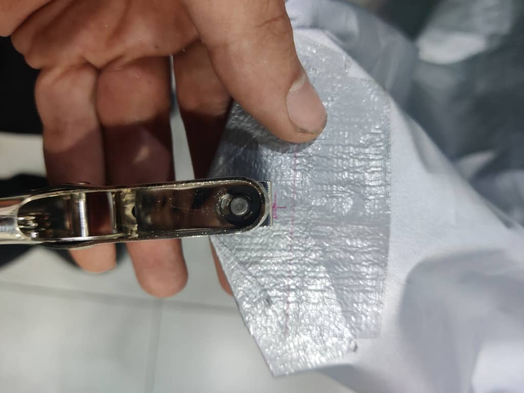
To attach the suspension lines, I reinforced each of the eight corners with layers of duct tape, then carefully punched a hole through each corner. This allowed us to tie a rope to each corner, eventually gathering all eight ropes to a central attachment point for a balanced deployment.
We then moved on to testing. On a sunny day with moderate wind, I tested the parachute’s deployment by running and observing how it unfolded. The test confirmed that the design opened consistently and provided sufficient drag, making it suitable for the final rocket deployment system.
Week 4: ESP32C3 programming + Week 9: Barometer + Week 10: Buzzer + LEDs + RBF
ESP32C3
ESP32C3
For the programming aspect of the project, I started by testing each subsystem individually to ensure proper functionality before integrating them into the final flight controller. The system is composed of four key components: LEDs, servos, a Remove Before Flight (RBF) pin, a buzzer, and a barometric sensor (BME680).
- LEDs:
I used the classic "blink" test in the Arduino IDE to confirm that each LED was wired correctly and functioning as expected.
/*
  Blink

  Turns an LED on for one second, then off for one second, repeatedly.

  Most Arduinos have an on-board LED you can control. On the UNO, MEGA and ZERO
  it is attached to digital pin 13, on MKR1000 on pin 6. LED_BUILTIN is set to
  the correct LED pin independent of which board is used.
  If you want to know what pin the on-board LED is connected to on your Arduino
  model, check the Technical Specs of your board at:
  https://docs.arduino.cc/hardware/

  modified 8 May 2014
  by Scott Fitzgerald
  modified 2 Sep 2016
  by Arturo Guadalupi
  modified 8 Sep 2016
  by Colby Newman

  This example code is in the public domain.

  https://docs.arduino.cc/built-in-examples/basics/Blink/
*/

// the setup function runs once when you press reset or power the board
void setup() {
  // initialize digital pin LED_BUILTIN as an output.
  pinMode(LED_BUILTIN, OUTPUT);
}

// the loop function runs over and over again forever
void loop() {
  digitalWrite(LED_BUILTIN, HIGH);  // turn the LED on (HIGH is the voltage level)
  delay(1000);                      // wait for a second
  digitalWrite(LED_BUILTIN, LOW);   // turn the LED off by making the voltage LOW
  delay(1000);                      // wait for a second
}
- Servos:
To control the servo motor, I installed the ESP32Servo library and ran the sweep example. This confirmed both the control signal and power delivery were working correctly.
#include <ESP32Servo.h>

Servo myServo;          // create servo object
int servoPin = 5;       // GPIO 3 on ESP32-C3
int angle = 0;          // variable to store the servo position

void setup() {
  Serial.begin(115200);
  myServo.setPeriodHertz(50);       // Standard 50 Hz servo
  myServo.attach(servoPin, 500, 2400); // Min and Max pulse width in µs
}

void loop() {
  // Sweep from 0 to 180
  for (angle = 0; angle <= 180; angle += 1) {
    myServo.write(angle);
    delay(15);
  }

  // Sweep back from 180 to 0
  for (angle = 180; angle >= 0; angle -= 1) {
    myServo.write(angle);
    delay(15);
  }
}
- Remove Before Flight (RBF) Pin:
The RBF mechanism was implemented as a digital input with
INPUT_PULLUPmode, eliminating the need for an external resistor on the PCB. Testing confirmed that the system could reliably detect when the pin was inserted or removed./* Input Pull-up Serial This example demonstrates the use of pinMode(INPUT_PULLUP). It reads a digital input on pin 2 and prints the results to the Serial Monitor. The circuit: - momentary switch attached from pin 2 to ground - built-in LED on pin 13 Unlike pinMode(INPUT), there is no pull-down resistor necessary. An internal 20K-ohm resistor is pulled to 5V. This configuration causes the input to read HIGH when the switch is open, and LOW when it is closed. created 14 Mar 2012 by Scott Fitzgerald This example code is in the public domain. https://www.arduino.cc/en/Tutorial/InputPullupSerial */ void setup() { //start serial connection Serial.begin(9600); //configure pin 2 as an input and enable the internal pull-up resistor pinMode(2, INPUT_PULLUP); pinMode(13, OUTPUT); } void loop() { //read the pushbutton value into a variable int sensorVal = digitalRead(2); //print out the value of the pushbutton Serial.println(sensorVal); // Keep in mind the pull-up means the pushbutton's logic is inverted. It goes // HIGH when it's open, and LOW when it's pressed. Turn on pin 13 when the // button's pressed, and off when it's not: if (sensorVal == HIGH) { digitalWrite(13, LOW); } else { digitalWrite(13, HIGH); } }
- Buzzer:
I reused the same blink example used for the LEDs to test the buzzer, toggling it on and off to ensure it could produce sound at the right moments.
- Barometric Sensor (BME680):
I utilized the Adafruit BME680 example code provided in the Arduino IDE. This allowed me to confirm accurate readings for temperature, pressure, humidity, and gas resistance.
/***************************************************************************
  This is a library for the BME680 gas, humidity, temperature & pressure sensor

  Designed specifically to work with the Adafruit BME680 Breakout
  ----> http://www.adafruit.com/products/3660

  These sensors use I2C or SPI to communicate, 2 or 4 pins are required
  to interface.

  Adafruit invests time and resources providing this open source code,
  please support Adafruit and open-source hardware by purchasing products
  from Adafruit!

  Written by Limor Fried & Kevin Townsend for Adafruit Industries.
  BSD license, all text above must be included in any redistribution
 ***************************************************************************/

#include <Wire.h>
#include <SPI.h>
#include <Adafruit_Sensor.h>
#include "Adafruit_BME680.h"

#define BME_SCK 8
#define BME_MISO 9
#define BME_MOSI 19
#define BME_CS 20

#define SEALEVELPRESSURE_HPA (1013.25)

//Adafruit_BME680 bme(&Wire); // I2C
//Adafruit_BME680 bme(&Wire1); // example of I2C on another bus
//Adafruit_BME680 bme(BME_CS); // hardware SPI
Adafruit_BME680 bme(BME_CS, BME_MOSI, BME_MISO,  BME_SCK);

void setup() {
  Serial.begin(9600);
  while (!Serial);
  Serial.println(F("BME680 test"));

  if (!bme.begin()) {
    Serial.println("Could not find a valid BME680 sensor, check wiring!");
    while (1);
  }

  // Set up oversampling and filter initialization
  bme.setTemperatureOversampling(BME680_OS_8X);
  bme.setHumidityOversampling(BME680_OS_2X);
  bme.setPressureOversampling(BME680_OS_4X);
  bme.setIIRFilterSize(BME680_FILTER_SIZE_3);
  bme.setGasHeater(320, 150); // 320*C for 150 ms
}

void loop() {
  if (! bme.performReading()) {
    Serial.println("Failed to perform reading :(");
    return;
  }
  Serial.print("Temperature = ");
  Serial.print(bme.temperature);
  Serial.println(" *C");

  Serial.print("Pressure = ");
  Serial.print(bme.pressure / 100.0);
  Serial.println(" hPa");

  Serial.print("Humidity = ");
  Serial.print(bme.humidity);
  Serial.println(" %");

  Serial.print("Gas = ");
  Serial.print(bme.gas_resistance / 1000.0);
  Serial.println(" KOhms");

  Serial.print("Approx. Altitude = ");
  Serial.print(bme.readAltitude(SEALEVELPRESSURE_HPA));
  Serial.println(" m");

  Serial.println();
  delay(2000);
}
After all components passed their individual tests, I began integrating them into a unified control script, which served as the core of the rocket’s flight logic and parachute deployment system.
- LEDs:
Week 5: 3D Print Nose
3D Print Nose
3D Print Nose
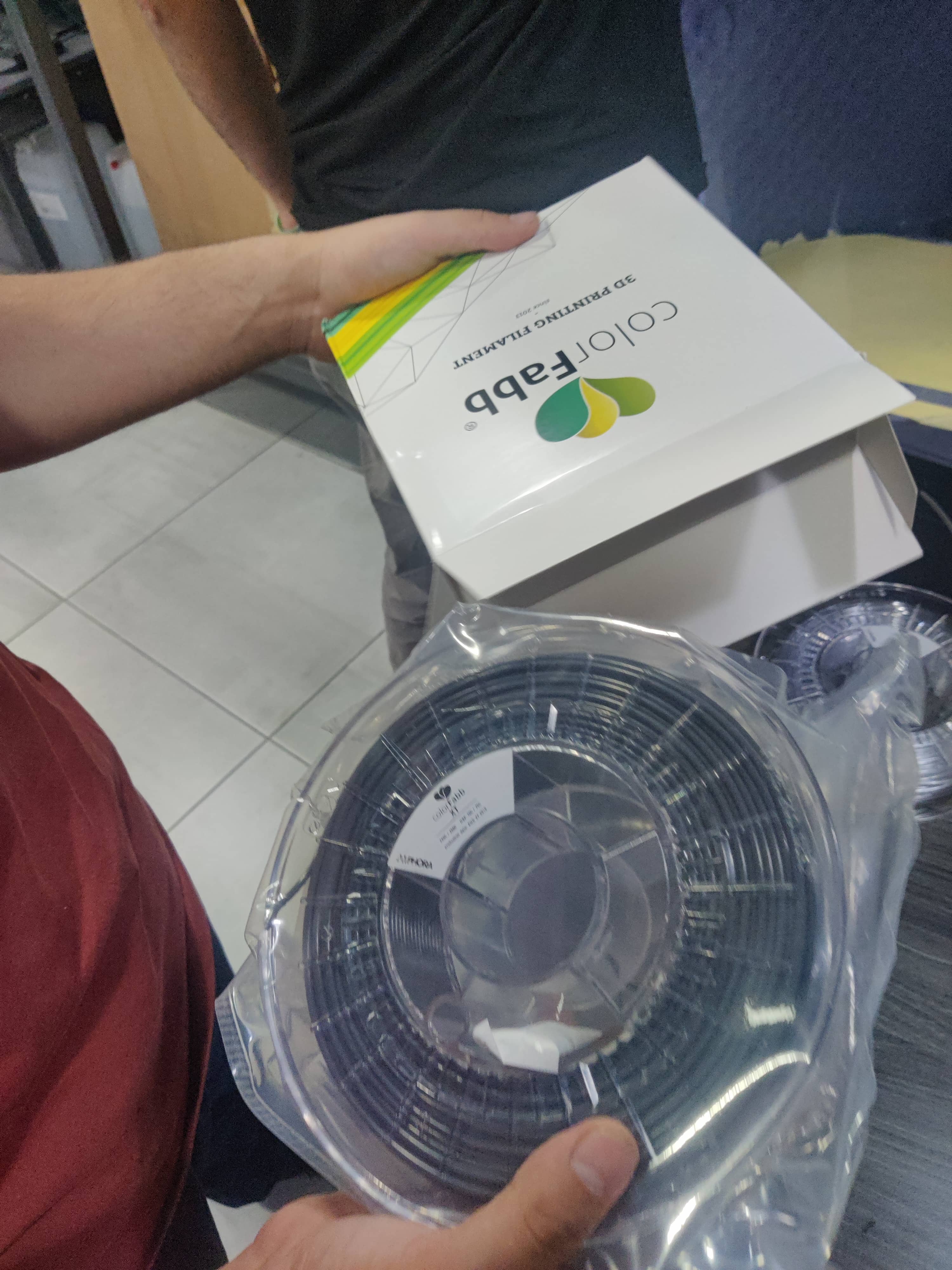
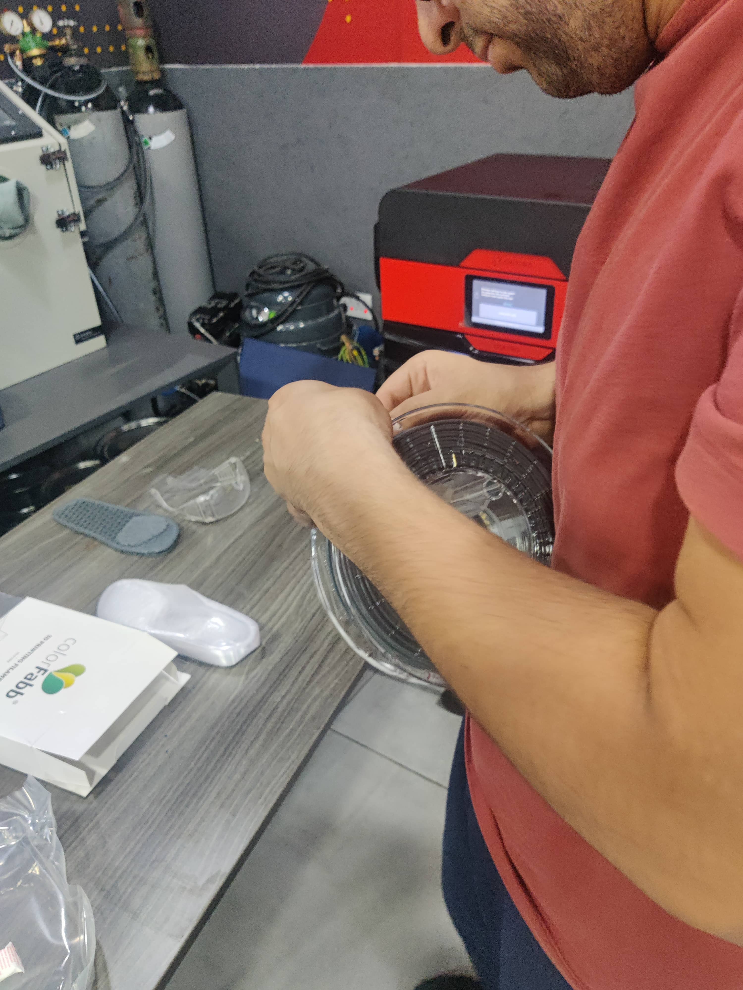
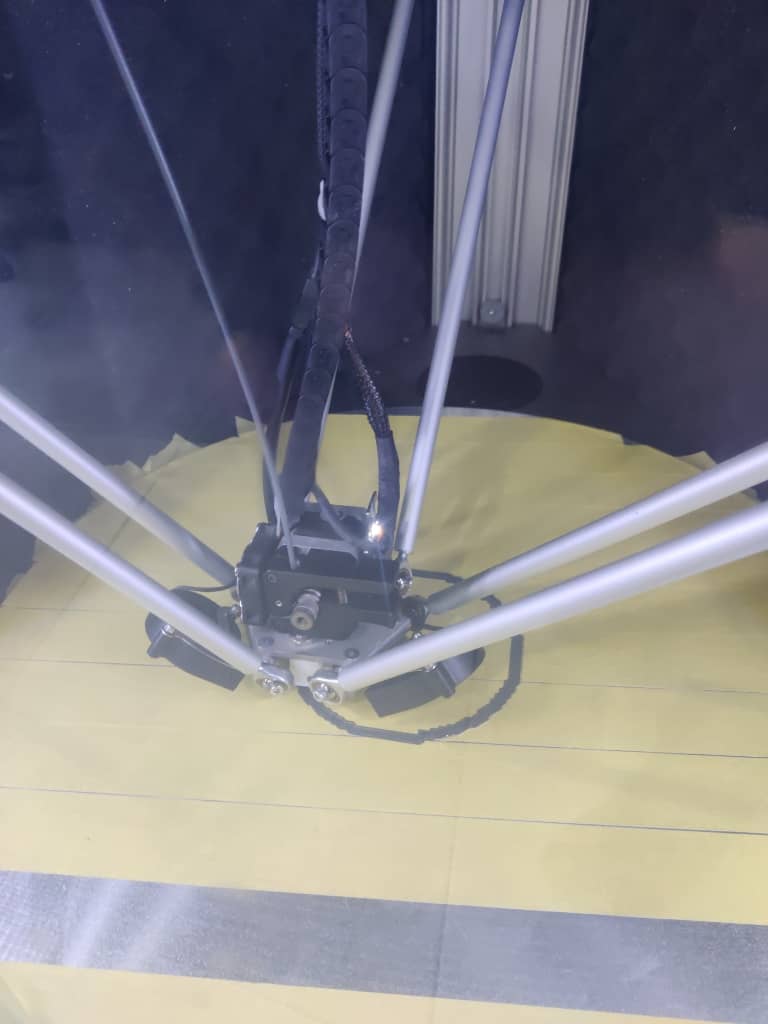
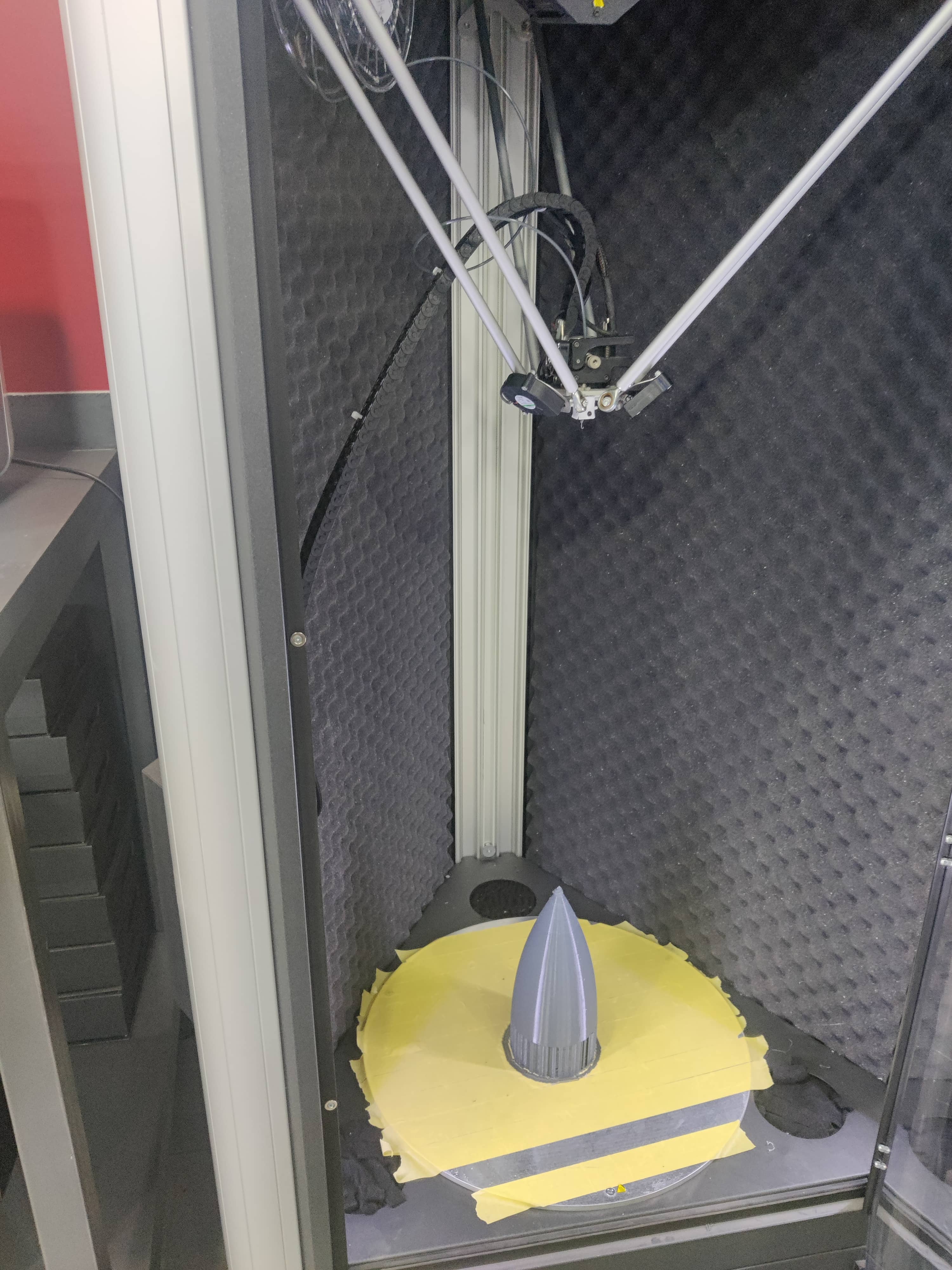
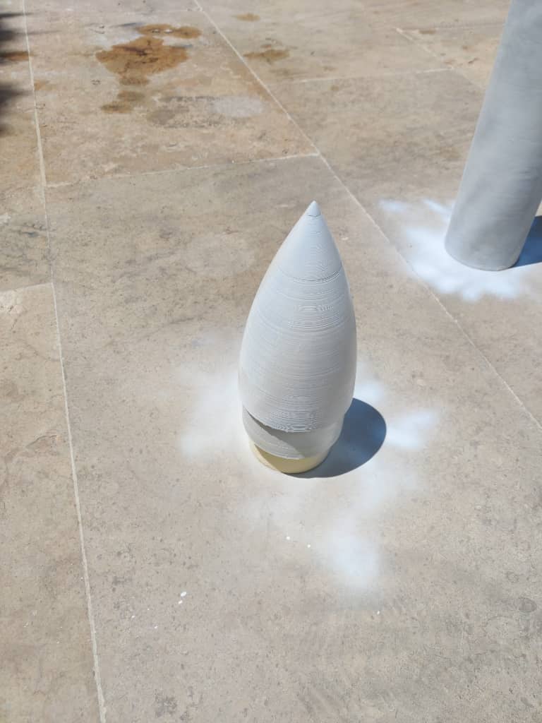
To fabricate the rocket's nose cone, I began by extracting the nose geometry from the Fusion 360 CAD model and exporting it as an STL file. I then imported the file into Simplify3D, where I customized the slicing settings to suit large-format printing.
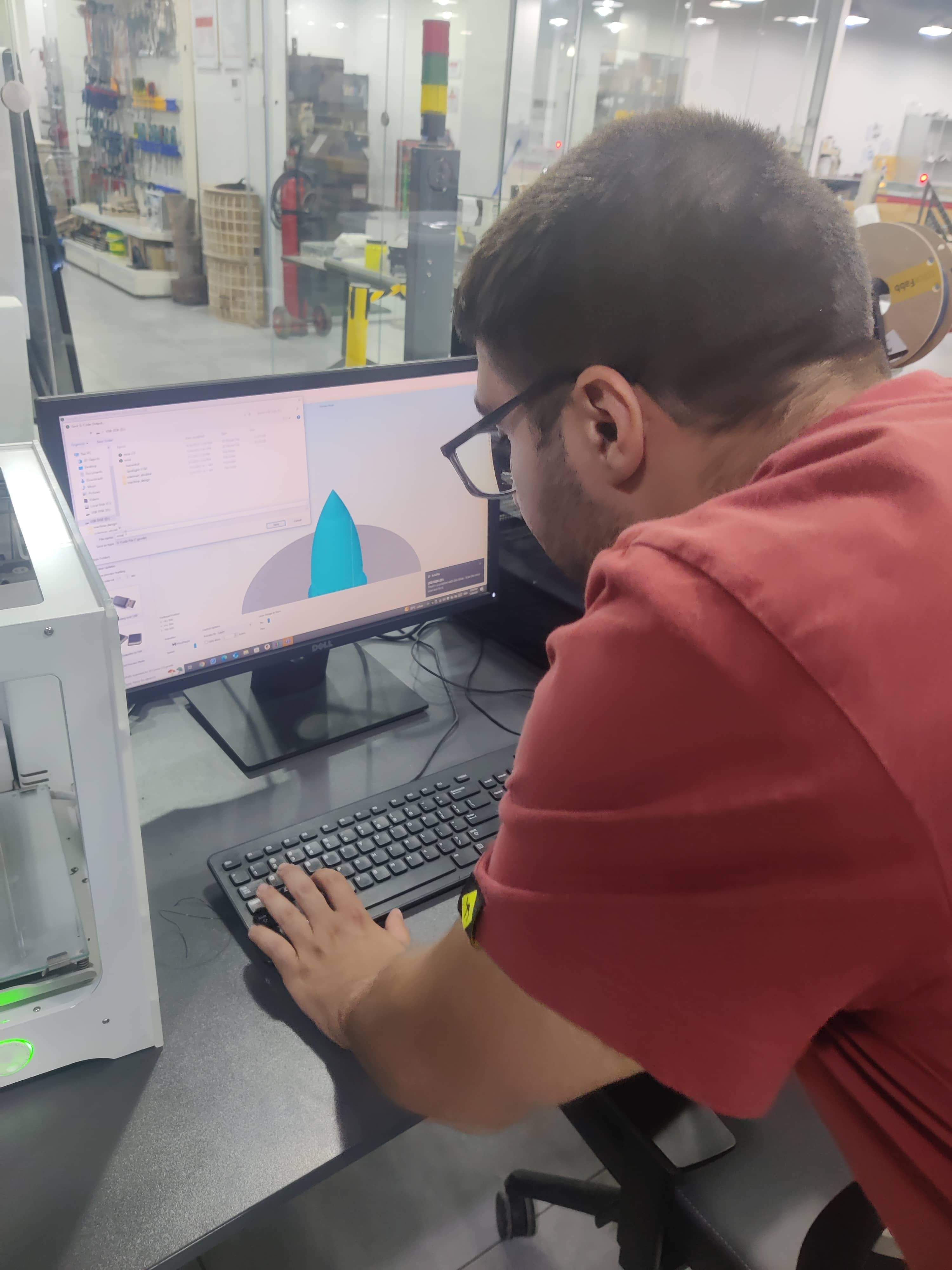
For material, I used a fresh roll of Gray XT filament, which I loaded into the WASP 4070 Industrial Delta 3D printer. With guidance from the lab instructors, we ensured an optimal first layer by fine-tuning the bed leveling and temperatures. The nozzle was set to 260°C, and the heated bed to 80°C.
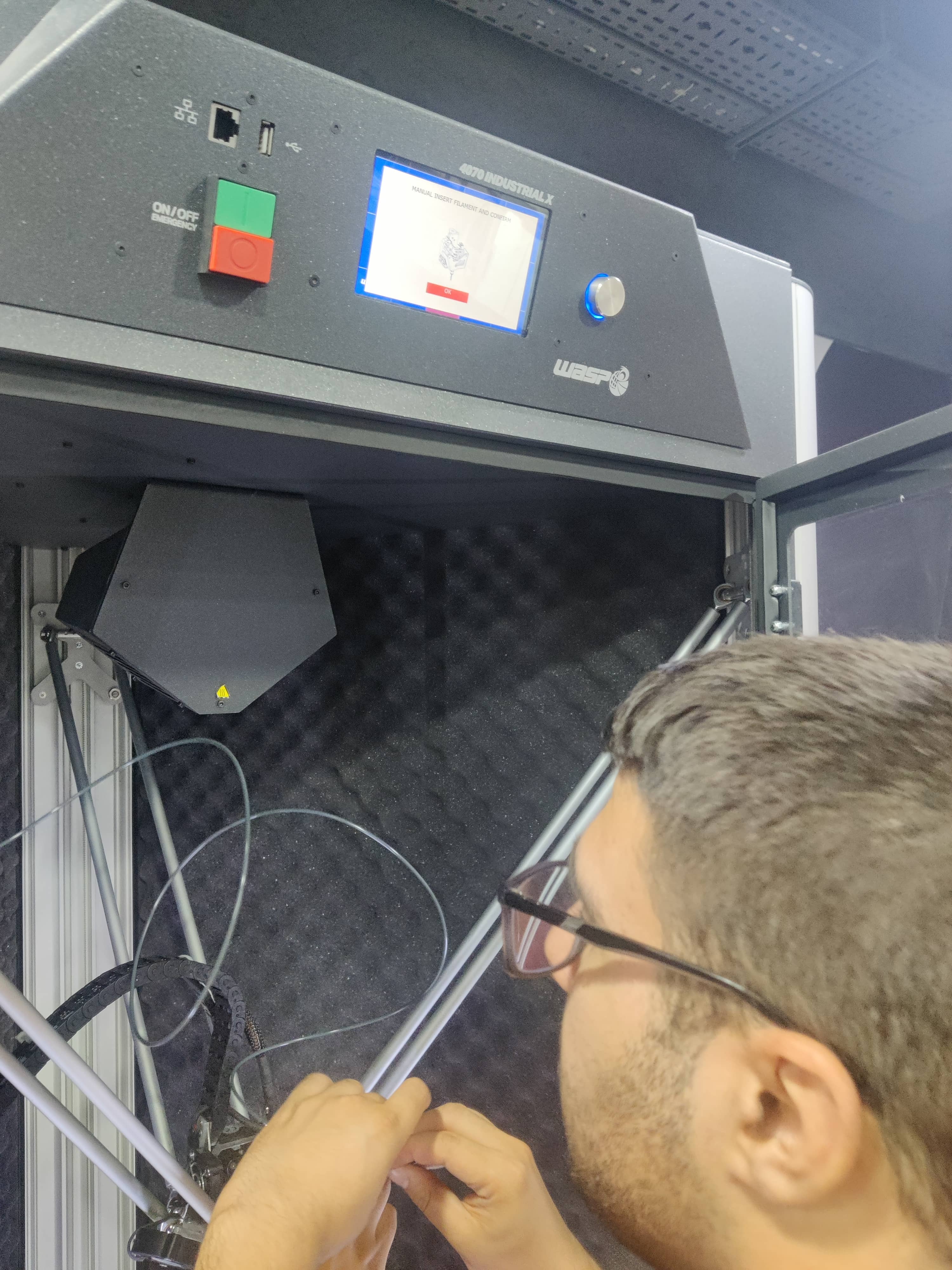
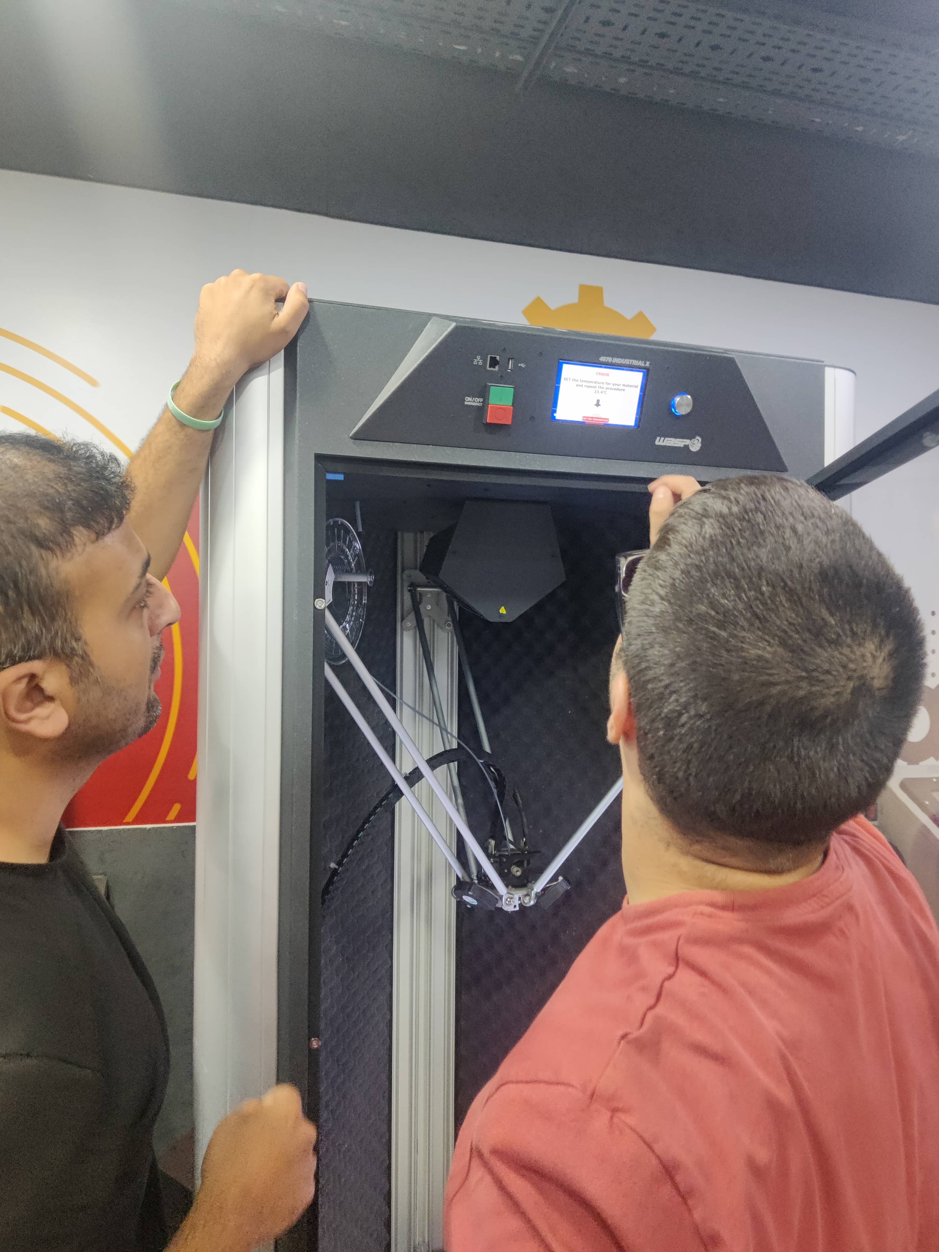
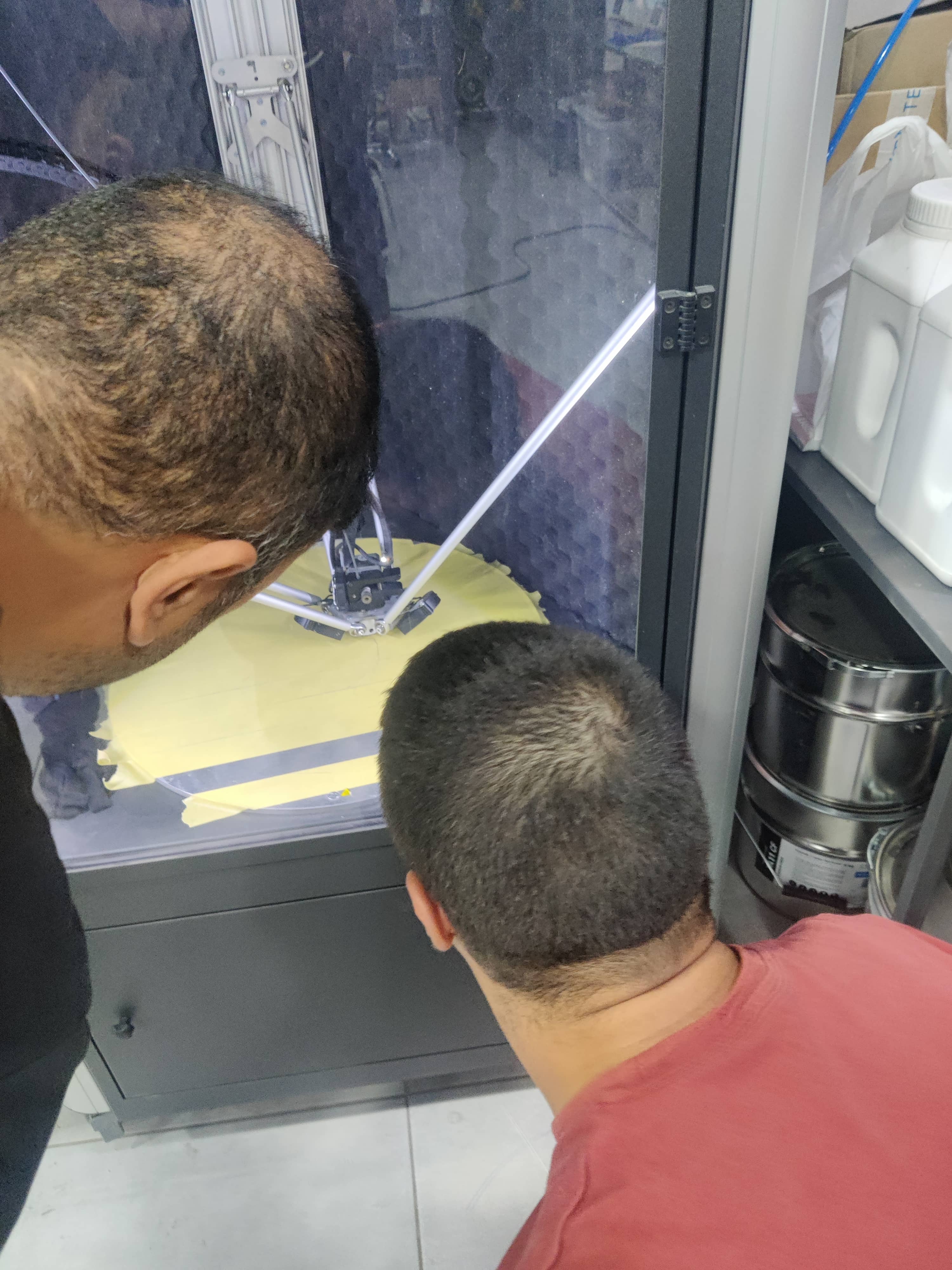
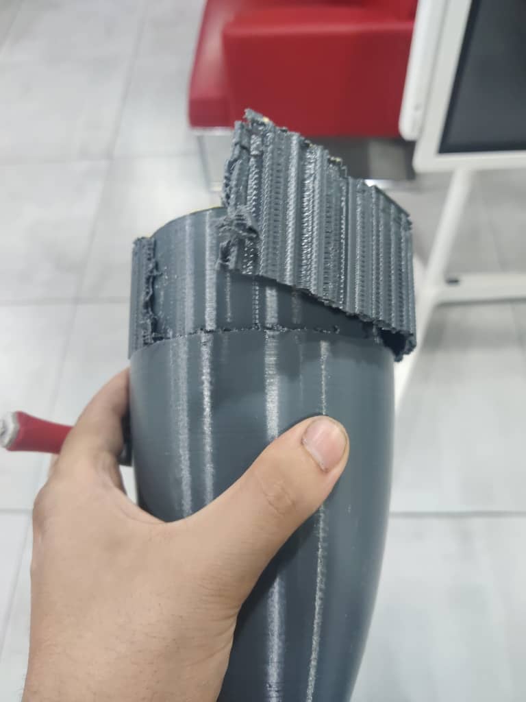
The print was extensive, taking nearly 25 continuous hours. We left it to print overnight and returned the next day to find it successfully completed. After cooling, I removed the support structures and performed a test fit with the fiberglass tube.
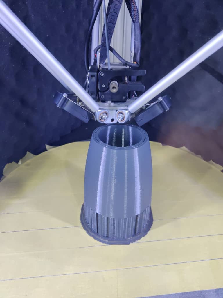
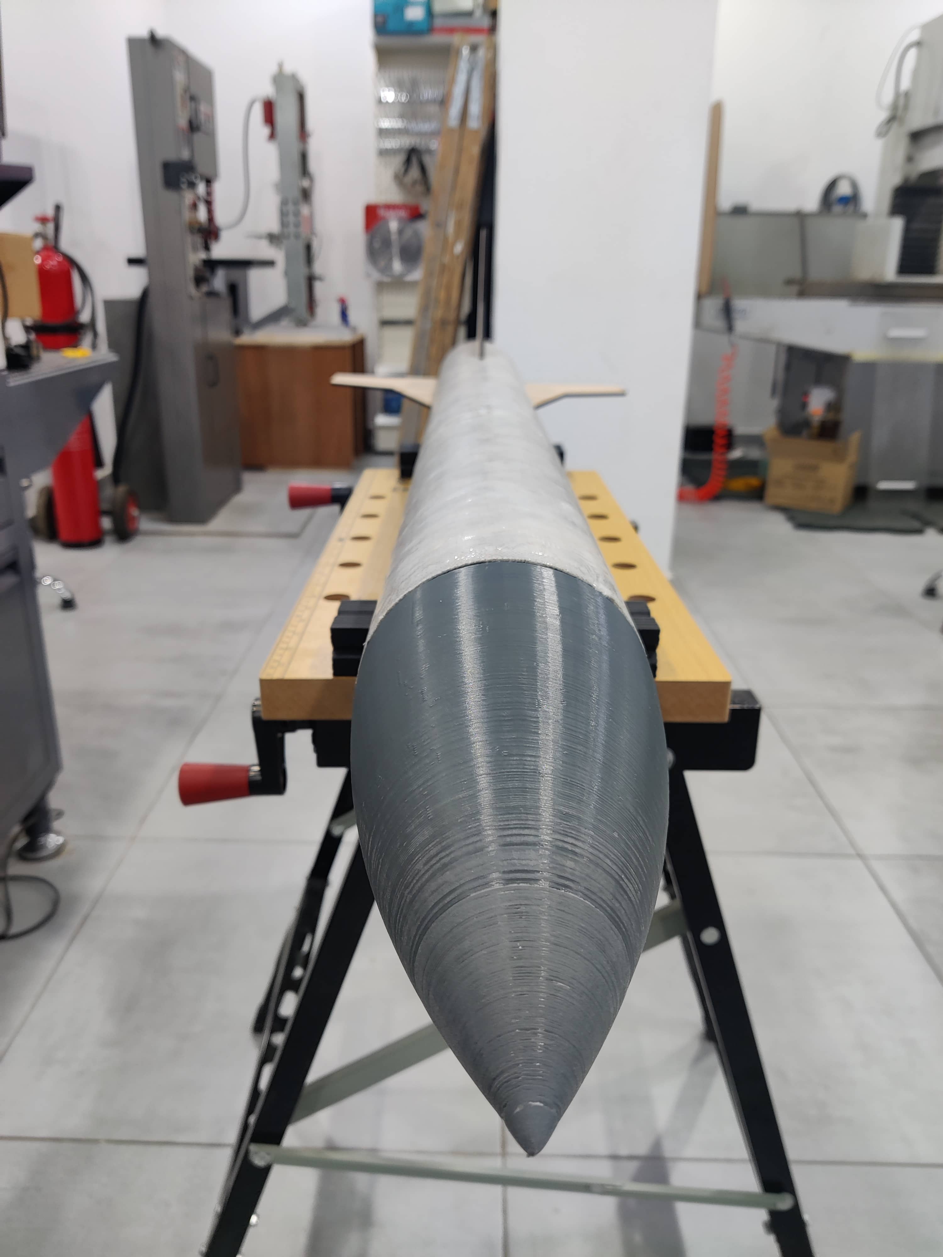
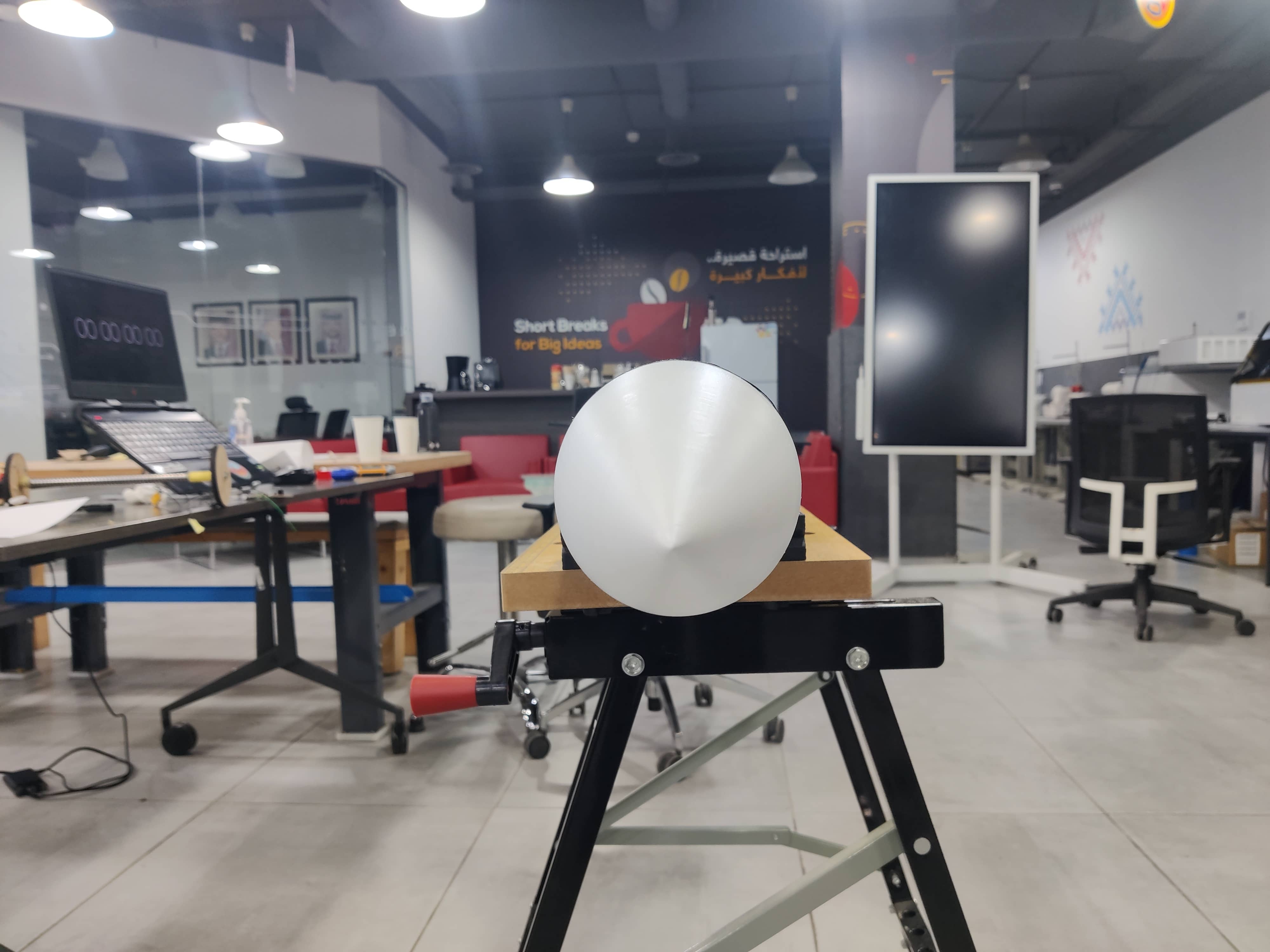
As seen in the photos, the nose cone wasn’t perfectly pointed at the tip. To resolve this, I used fine-grit sanding paper to smooth the surface and refine the shape.
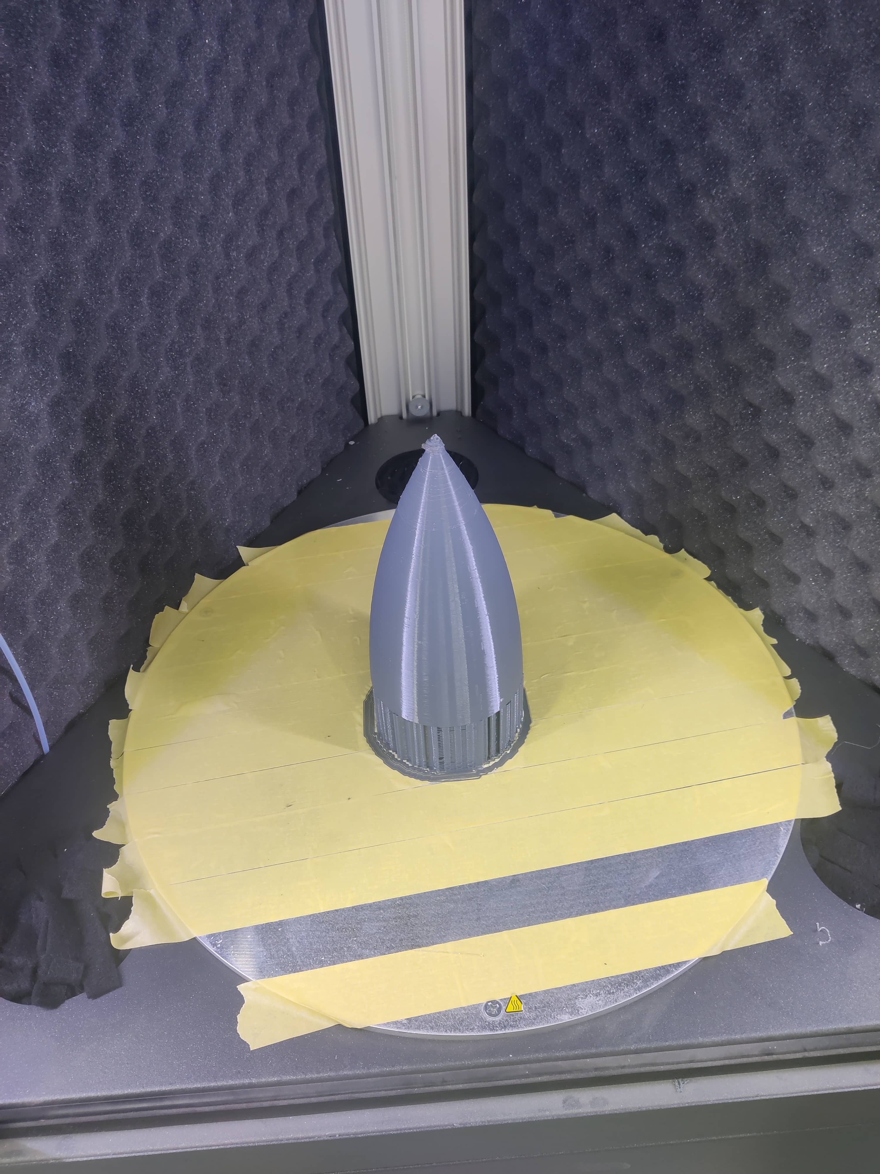
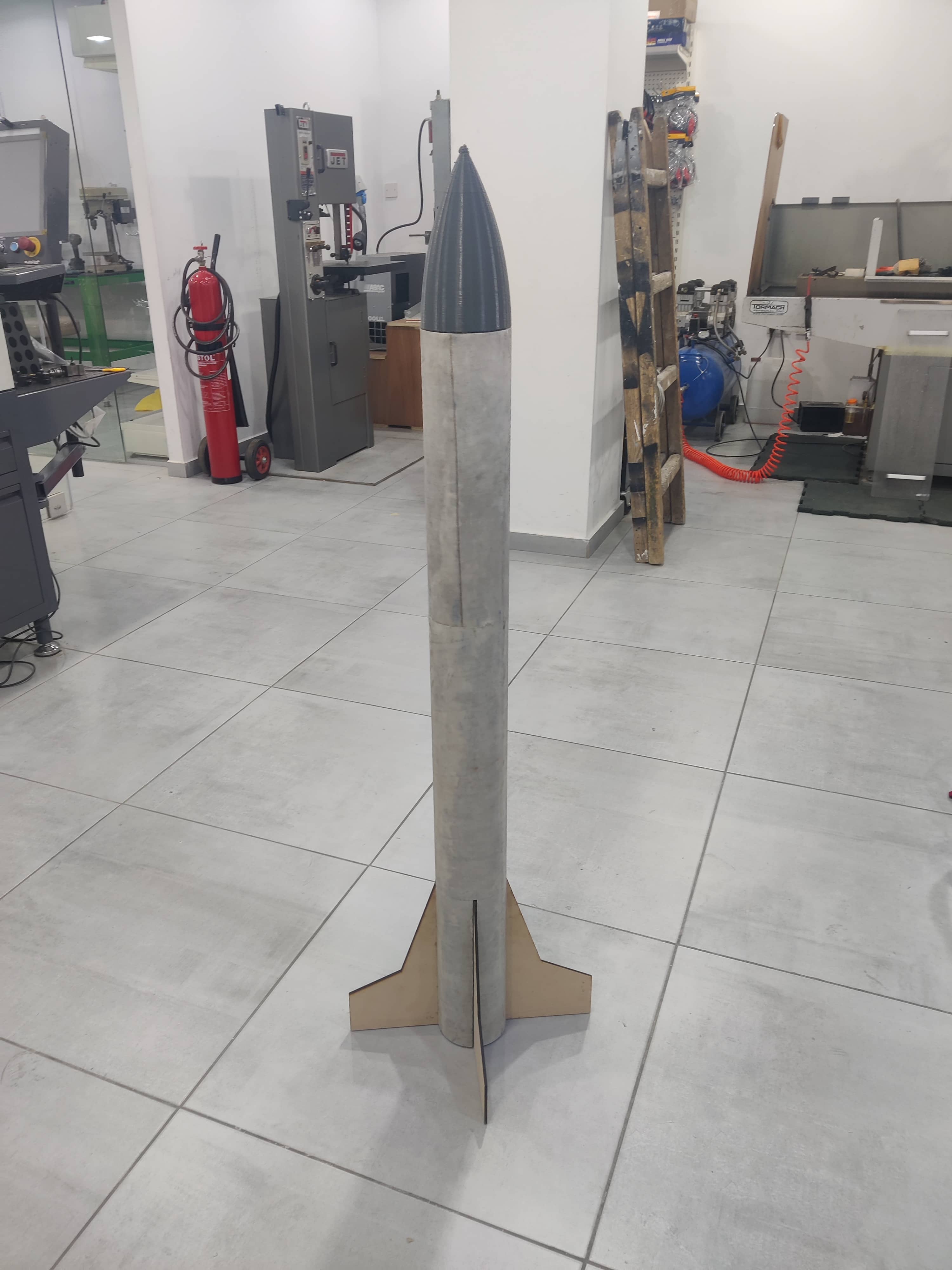
Finally, I applied two coats of white acrylic spray paint, giving it a smooth, clean finish that closely matched the intended design.
Week 6: Flight Controller design + Logic + Code
Flight Controller design
AL-HAITHAM 1 Flight Controller design V4
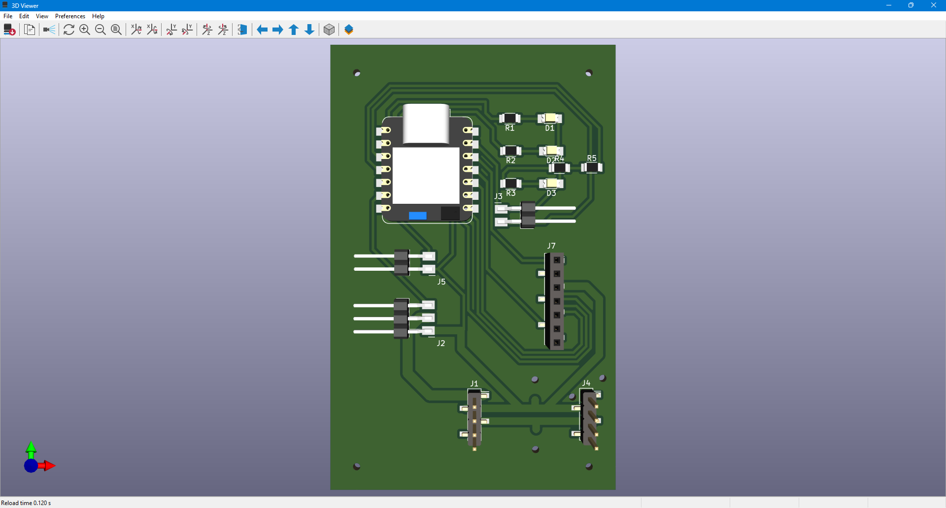
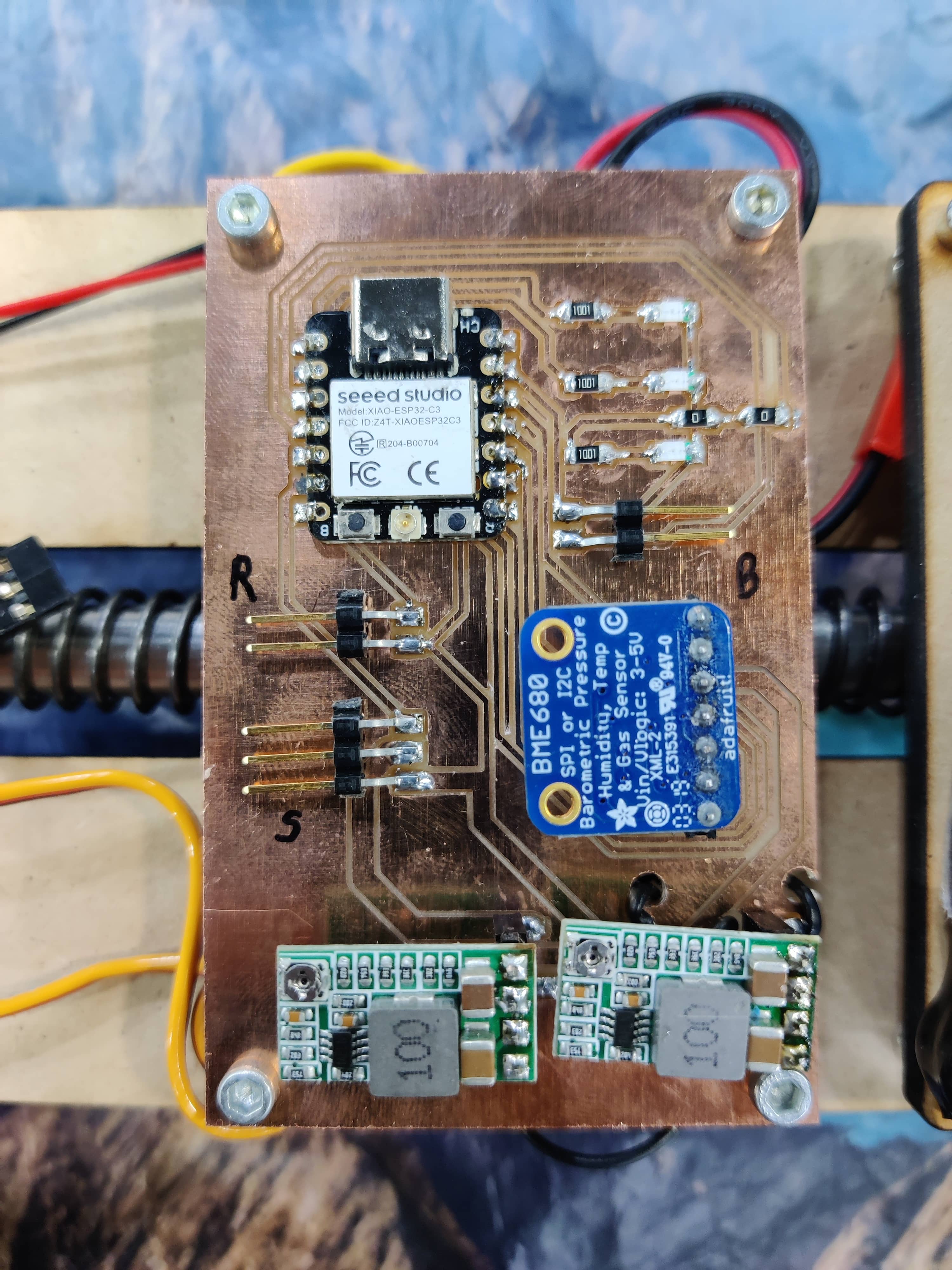
For the flight controller, I used KiCad 9 to design a custom PCB that integrates all the key input and output devices used in the system. The goal was to consolidate everything into a compact and efficient controller board while maintaining flexibility for debugging and part replacement.
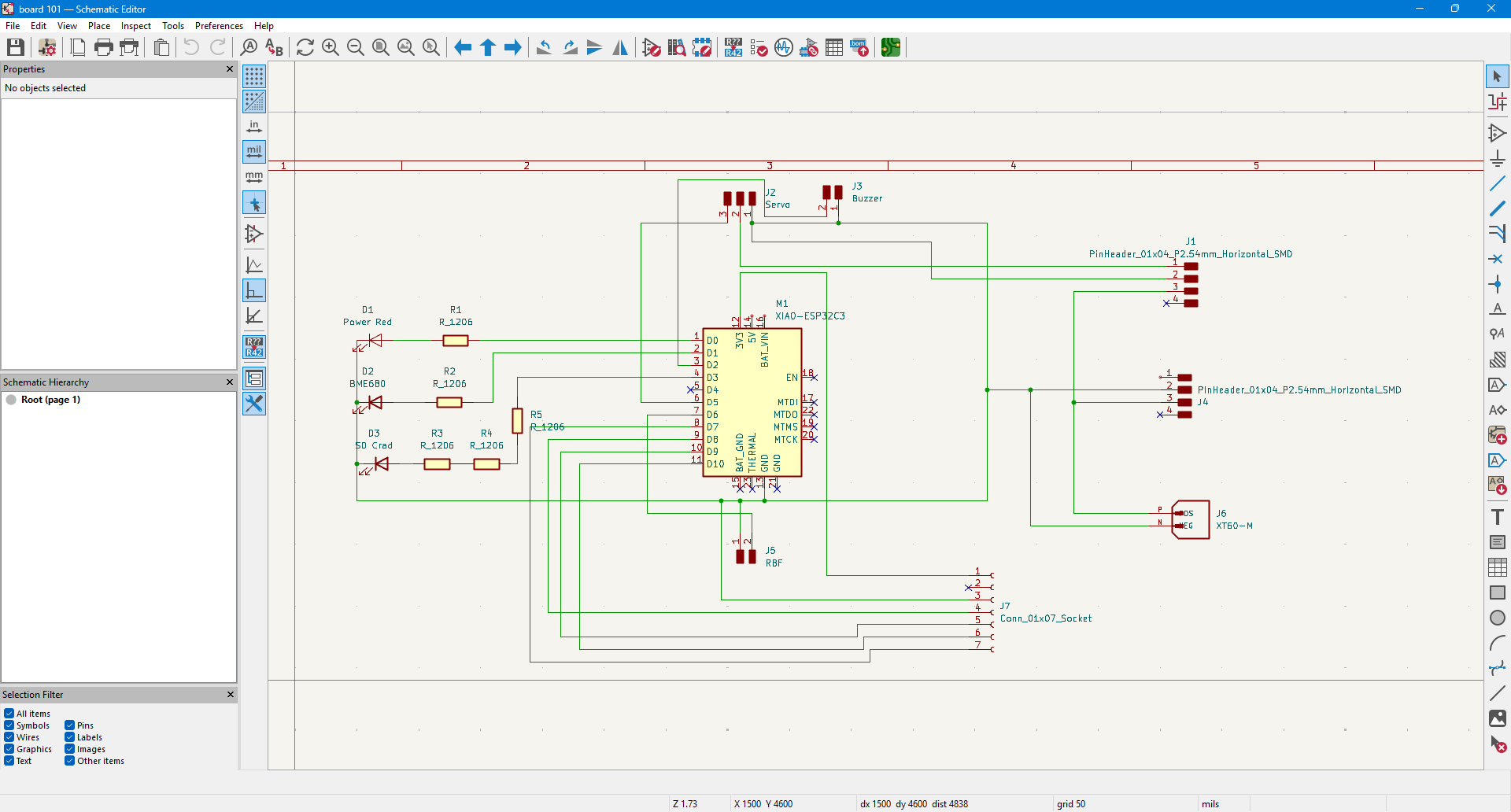
To achieve this, I implemented male and female header adapters to allow for easy swapping of components in case of malfunction during testing or flight. After laying out the schematic, I moved to the PCB editor to route the board.
Due to the complexity of the design and trace congestion, I used a few 0-ohm resistors as jumpers to bridge certain paths and resolve trace entanglement. Some traces were intentionally made thicker, particularly those carrying higher currents from the 2-cell LiPo battery to the power regulation system. This system steps the voltage down to 5V for the servos and 3.3V for logic-level components.
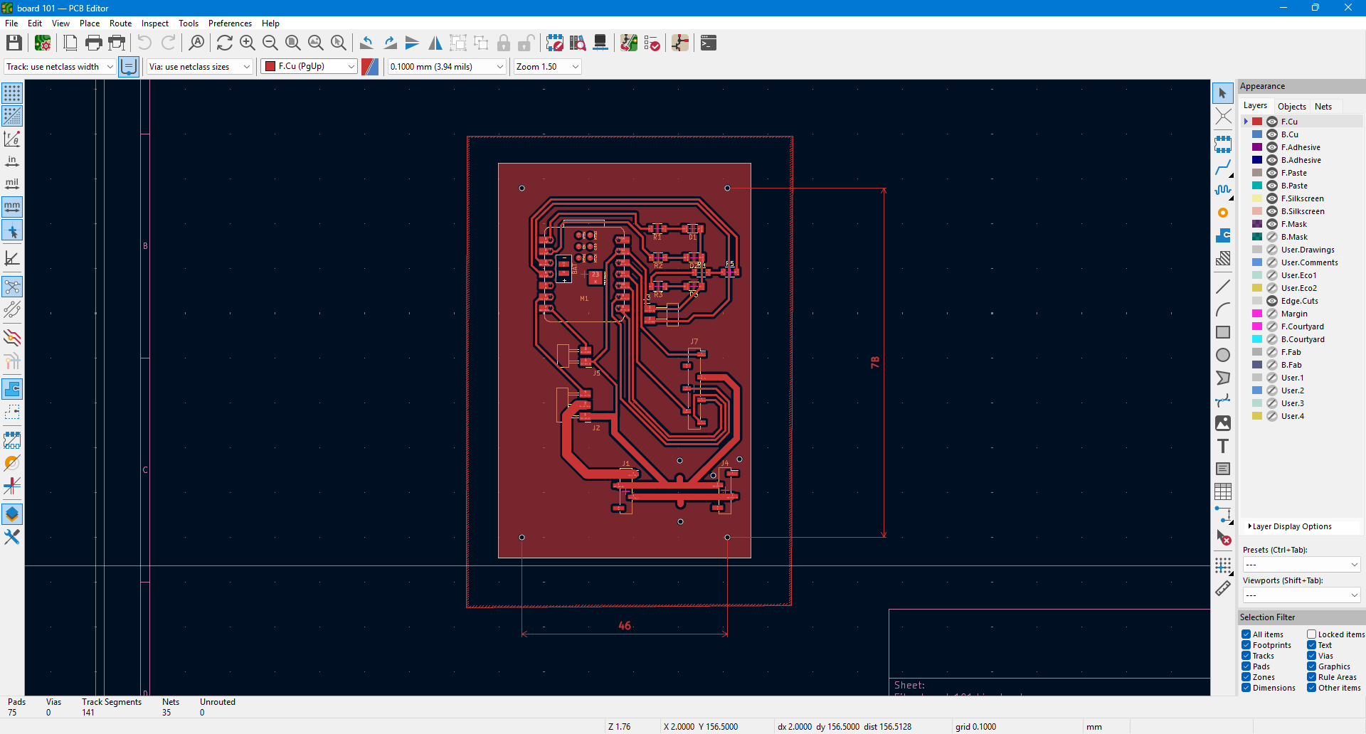
Once routing was complete, I reviewed the 3D model of the PCB to ensure it would fit within the fiberglass rocket body. I also added mounting holes in the corners so it could be securely fixed to the parachute deployment mechanism using spacers.
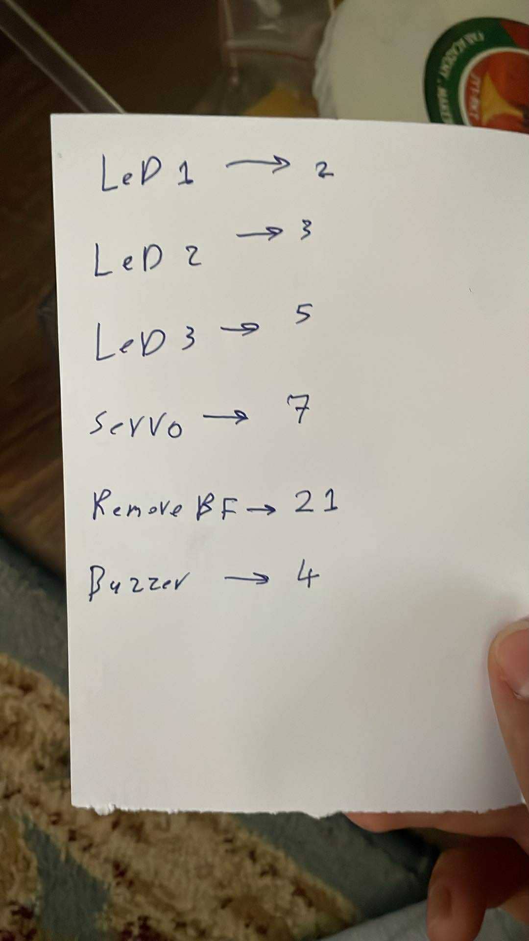
To streamline the future programming and wiring process, I documented the pin mapping by labeling each GPIO’s function on paper and matching it to the KiCad layout. This step was critical for ensuring accurate connections and smooth integration during system testing.

System Logic:
1. Initialization (
setup()function)- Serial communication starts for debugging.
- Pin configuration is set:
RBF_PIN(Remove Before Flight pin) is input.
BUZZER_PINis output.
- Servo is attached and set to 180° (arming position).
- BME680 barometric sensor is initialized and configured for accurate altitude readings.
2. Waiting for Launch Preparation (
loop()function)RBF logic:
- The system waits until the
RBF_PIN(Remove Before Flight pin) is pulled LOW (i.e., shorted or pulled to GND).
- Once detected:
- The current time is recorded in
rbfRemovedTime.
- The buzzer beeps once to confirm the system is armed and entering delay.
- The current time is recorded in
3. 2-Minute Arming Delay
- After RBF is removed, the system waits 2 minutes (120,000 ms).
- During this time, nothing else happens—this is your safety delay before launch.
4. System Starts After 2 Minutes
- After 2 minutes, the system:
- Beeps again
- Prints altitude to Serial Monitor for testing
5. Real-Time Flight Logging
- On every loop:
- The BME680 reads pressure.
- Altitude is calculated using the standard barometric formula.
- Altitude is printed on the serial monitor.
6. Apogee Detection (Key Logic)
- The code checks if the rocket is still gaining altitude.
- If altitude keeps increasing, it keeps updating
apogeeAltitudeandapogeeTime.
- Once altitude stops increasing for more than 2 seconds:
- Apogee is confirmed.
- Servo is activated → rotates from 180° to 0°, releasing the parachute.
deployed = trueis set.
7. Landing Detection
After deployment:
- The code monitors the altitude readings:
- If the altitude is stable (±0.2 m) for over 5 seconds,
- It assumes the rocket has landed.
- The buzzer is triggered to continuously beep so you can find the rocket on the ground.
What the System Does (Full Timeline):
- Power ON → System waits for RBF pin to be pulled
- RBF pulled → 1 beep → 2-minute wait
- After 2 minutes → 2nd beep
- Rocket launches → Altitude increases
- Apogee detected (altitude stops increasing for 2 seconds) → Servo activates → parachute deploys
- Altitude stabilizes after landing → Continuous buzzer sound helps you locate it
Code
Code v3.4
#include <Wire.h>
#include <Adafruit_BME680.h>
#include <ESP32Servo.h>

#define RBF_PIN 21        // Remove Before Flight pin
#define BUZZER_PIN 4     // Buzzer pin
#define SERVO_PIN 7      // Servo pin

#define LED_ARMED 2      // Green LED - RBF removed
#define LED_READY 3      // Yellow LED - Logging/Ready
#define LED_DEPLOYED 5   // Red LED - Deployed or Landed

Adafruit_BME680 bme;     // BME680 sensor object
Servo parachuteServo;

bool rbfRemoved = false;
unsigned long rbfRemovedTime = 0;
bool startLogging = false;
bool deployed = false;
float apogeeAltitude = 0;
unsigned long apogeeTime = 0;
unsigned long stableStartTime = 0;

float lastAltitude = 0;

void setup() {
  Serial.begin(9600);
  pinMode(RBF_PIN, INPUT_PULLUP);
  pinMode(BUZZER_PIN, OUTPUT);
  pinMode(LED_ARMED, OUTPUT);
  pinMode(LED_READY, OUTPUT);
  pinMode(LED_DEPLOYED, OUTPUT);

  digitalWrite(LED_ARMED, LOW);
  digitalWrite(LED_READY, LOW);
  digitalWrite(LED_DEPLOYED, LOW);

  parachuteServo.attach(SERVO_PIN);
  parachuteServo.write(180);  // Arm position

  if (!bme.begin()) {
    Serial.println("BME680 not found");
    while (1);
  }

  bme.setTemperatureOversampling(BME680_OS_8X);
  bme.setHumidityOversampling(BME680_OS_2X);
  bme.setPressureOversampling(BME680_OS_4X);
  bme.setIIRFilterSize(BME680_FILTER_SIZE_3);
  bme.setGasHeater(320, 150);
}

void loop() {
  unsigned long currentTime = millis();

  // Wait for RBF pin to be pulled low
  if (!rbfRemoved && digitalRead(RBF_PIN) == LOW) {
    rbfRemoved = true;
    rbfRemovedTime = currentTime;
    tone(BUZZER_PIN, 1000, 500); // Beep once
    digitalWrite(LED_ARMED, HIGH);  // Green LED ON
    Serial.println("RBF removed, arming...");
  }

  // Wait 2 minutes after RBF removal
  if (rbfRemoved && !startLogging && (currentTime - rbfRemovedTime >= 120000)) {
    startLogging = true;
    tone(BUZZER_PIN, 1000, 500); // Beep again
    digitalWrite(LED_READY, HIGH);  // Yellow LED ON
    Serial.println("Ready for launch");
  }

  if (startLogging) {
    if (!bme.performReading()) {
      Serial.println("Failed to read from BME680");
      return;
    }

    float pressure = bme.pressure / 100.0;
    float altitude = 44330 * (1.0 - pow(pressure / 1013.25, 0.1903));

    Serial.print("Time: ");
    Serial.print(currentTime);
    Serial.print(" ms, Altitude: ");
    Serial.print(altitude);
    Serial.println(" m");

    // Apogee detection
    if (!deployed) {
      if (altitude > apogeeAltitude) {
        apogeeAltitude = altitude;
        apogeeTime = currentTime;
      } else if (currentTime - apogeeTime >= 2000) {
        parachuteServo.write(0);  // Deploy parachute
        Serial.println("Parachute deployed!");
        digitalWrite(LED_DEPLOYED, HIGH); // Red LED ON
        deployed = true;
        stableStartTime = currentTime;
      }
    }

    // Landing detection
    if (deployed) {
      if (abs(altitude - lastAltitude) < 0.2) {
        if (currentTime - stableStartTime >= 5000) {
          tone(BUZZER_PIN, 2000); // Continuous beep
          digitalWrite(LED_DEPLOYED, HIGH); // Red LED ON
        }
      } else {
        stableStartTime = currentTime;
      }
    }

    lastAltitude = altitude;
  }

  delay(500);
}
Week 8: PCB
PCB
PCB
To fabricate the PCB for the flight controller, I used the Roland SRM-20 milling machine. After completing the design in KiCad, I used MODS to generate the toolpaths for both the traces and the board outline.
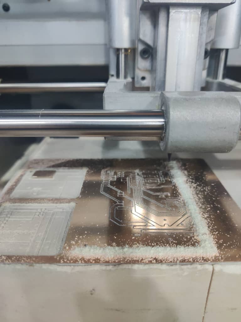
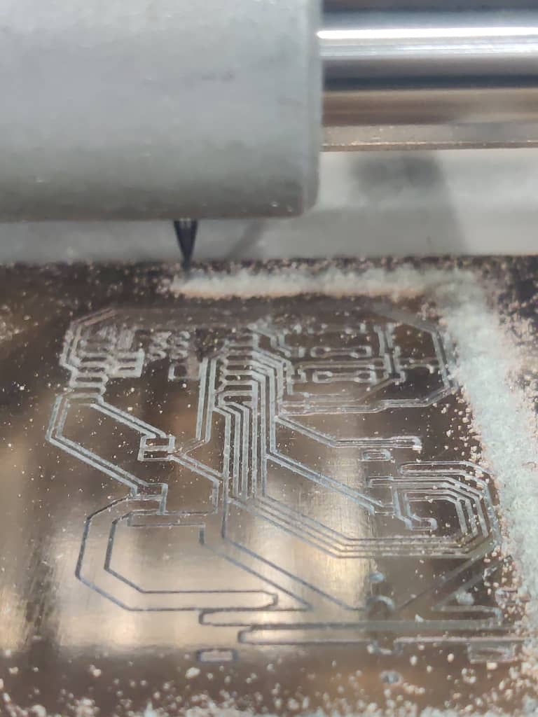
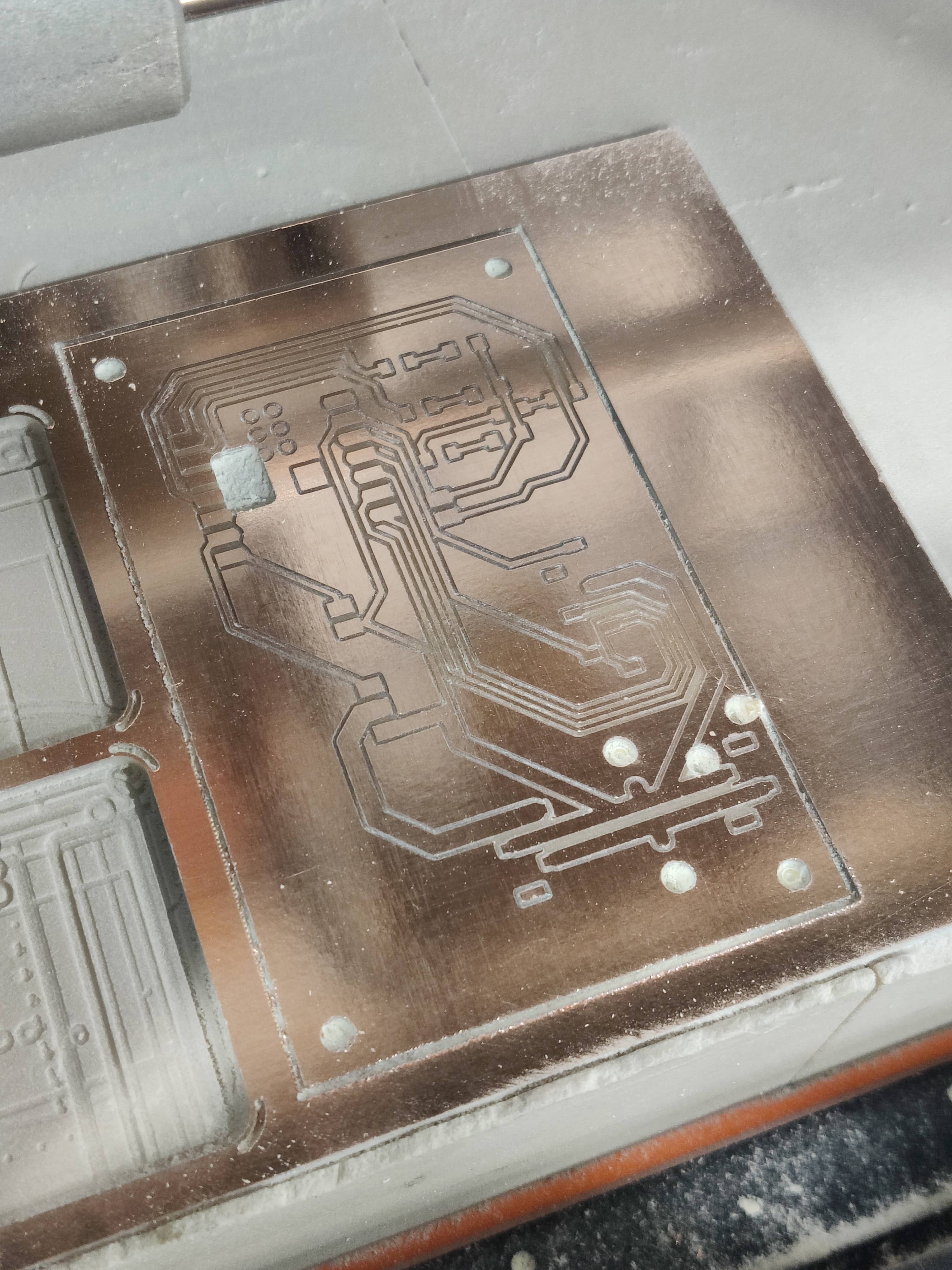
Once the PCB was milled, I referred back to the previously documented GPIO pin mapping, which linked each pin to its respective input or output device. This made the testing process much smoother. I began testing each component individually — from servos and LEDs to sensors and the buzzer — and confirmed that all devices were functioning as expected.
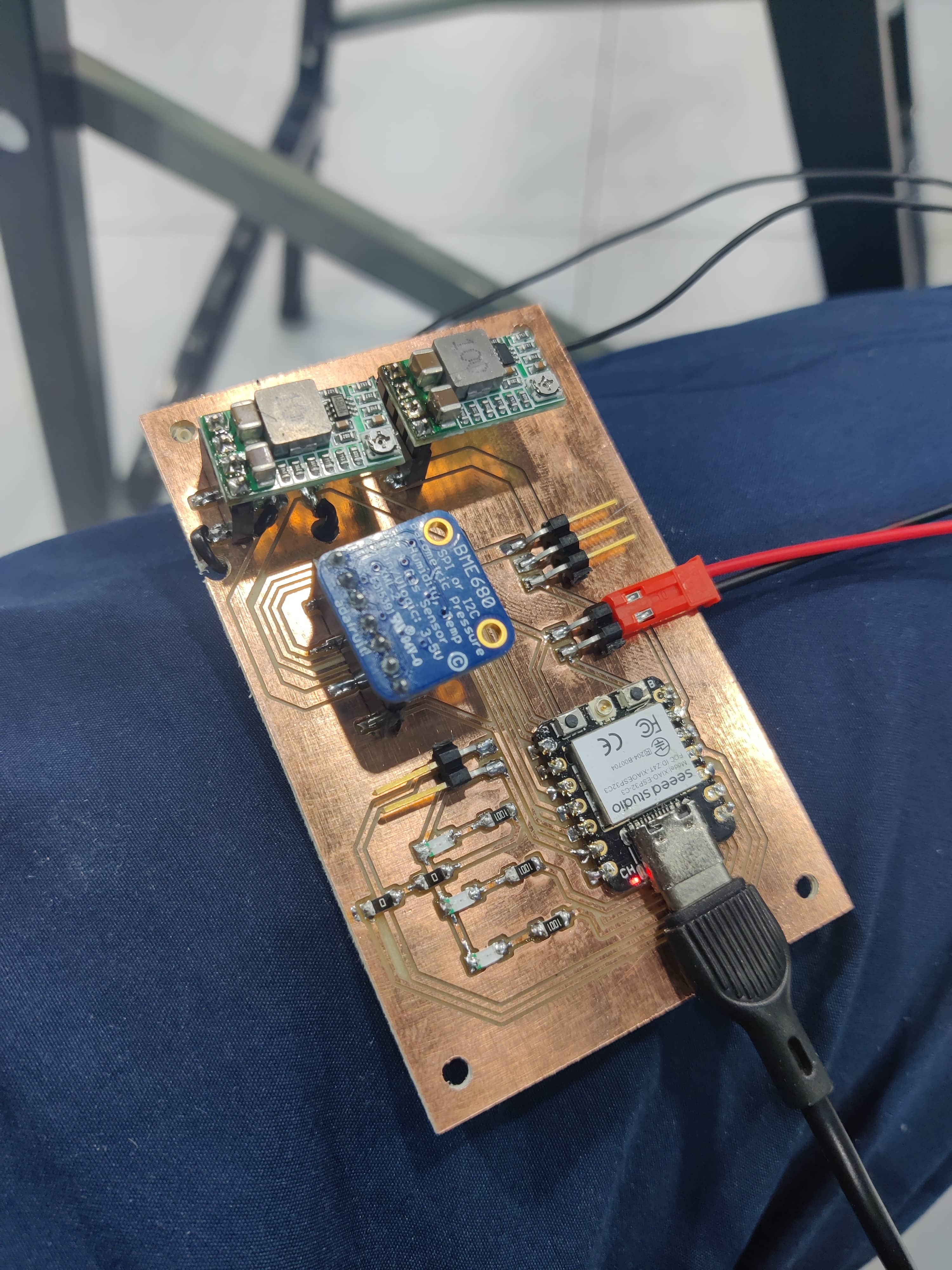
After successful testing, I used spacers to mount the PCB directly onto the parachute deployment mechanism. With careful wire management, I was able to secure all connections neatly and ensure the system was both reliable and organized inside the fiberglass rocket body.
Week 15: Processing Control Station
Processing Control Station
Processing Control Station
For monitoring the rocket's performance, I designed a custom control station using Processing. The goal was to create a visual interface that receives real-time data from the barometric sensor onboard the rocket. This included humidity, temperature, pressure, gas resistance, and altitude readings.
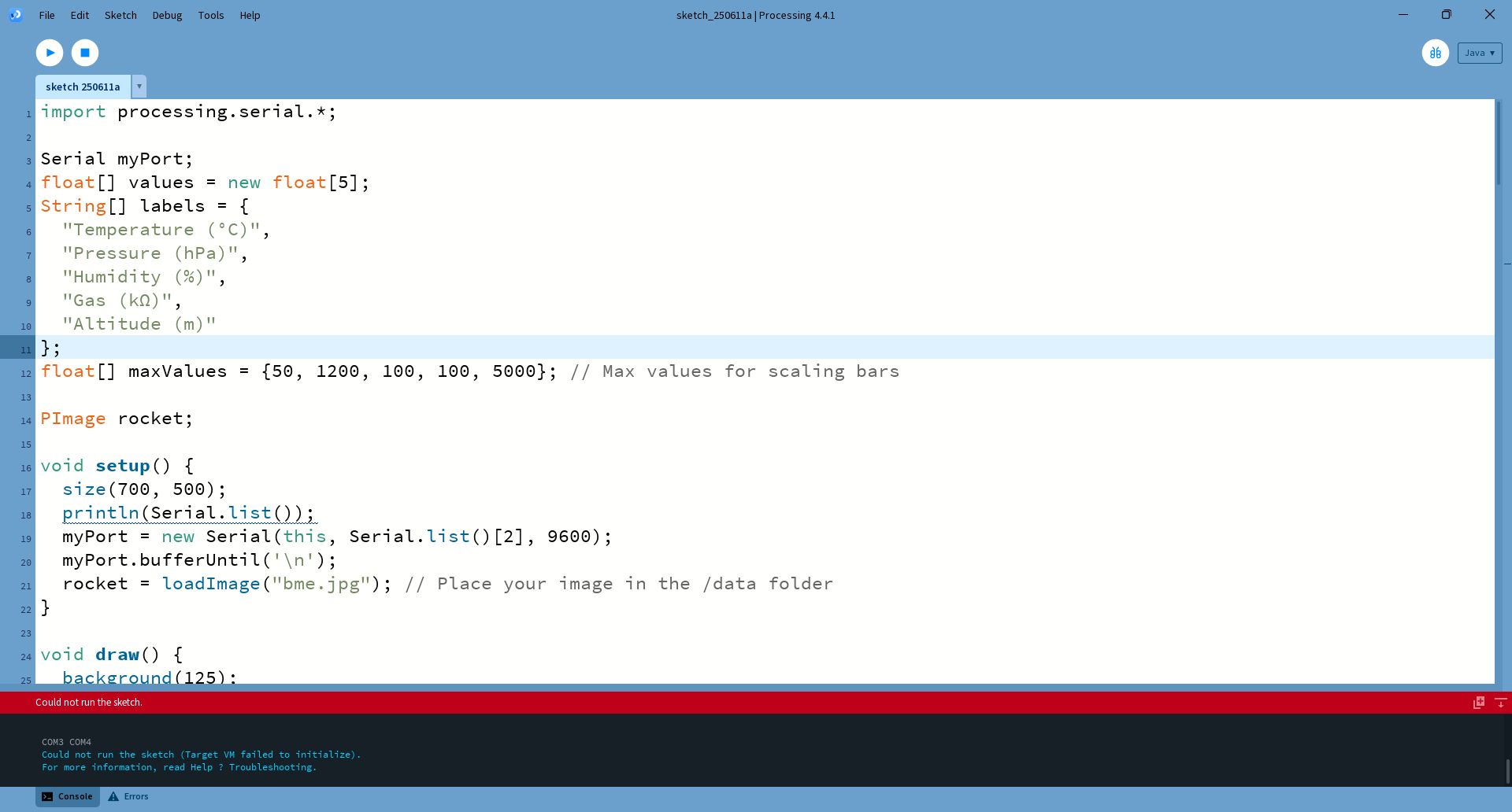
By serial communication between the Arduino and Processing, I was able to stream sensor data live into a graphical user interface (GUI). This allowed me to monitor the rocket's environmental and altitude data, offering both real-time feedback and a visual representation of the Sensor behavior.
import processing.serial.*;

Serial myPort;
float[] values = new float[5];
String[] labels = {
  "Temperature (°C)",
  "Pressure (hPa)",
  "Humidity (%)",
  "Gas (kΩ)",
  "Altitude (m)"
};
float[] maxValues = {50, 1200, 100, 100, 5000}; // Max values for scaling bars

PImage rocket;

void setup() {
  size(700, 500);
  println(Serial.list());
  myPort = new Serial(this, Serial.list()[2], 9600);
  myPort.bufferUntil('\n');
  rocket = loadImage("bme.jpg"); // Place your image in the /data folder
}

void draw() {
  background(125);

  // Title
  fill(255);
  textSize(28);
  textAlign(CENTER);
  text(" Alhaitham 1 Educational Rocket Control Station", width/2, 40);

  // Draw bars and labels
  textSize(14);
  for (int i = 0; i < values.length; i++) {
    float x = 60;
    float y = 80 + i * 70;
    float barWidth = map(values[i], 0, maxValues[i], 0, 200);

    fill(100, 200, 250);
    rect(x, y, barWidth, 30, 7);

    fill(255);
    textAlign(LEFT);
    text(labels[i], x + 210, y + 20);

    // Draw value text
    textAlign(RIGHT);
    text(nf(values[i], 1, 2), x + barWidth - 10, y + 20);
  }

  // Draw rocket image in the center
  //image(rocket, width/2 - 50, height - 220, 100, 200);
}

void serialEvent(Serial p) {
  String input = trim(p.readStringUntil('\n'));
  if (input != null) {
    String[] parts = split(input, ',');
    if (parts.length == 5) {
      for (int i = 0; i < 5; i++) {
        values[i] = float(parts[i]);
      }
    }
  }
}
Week 16: Electronics + Mechanical + Control System Integration
Electronics + Mechanical + Control System Integration
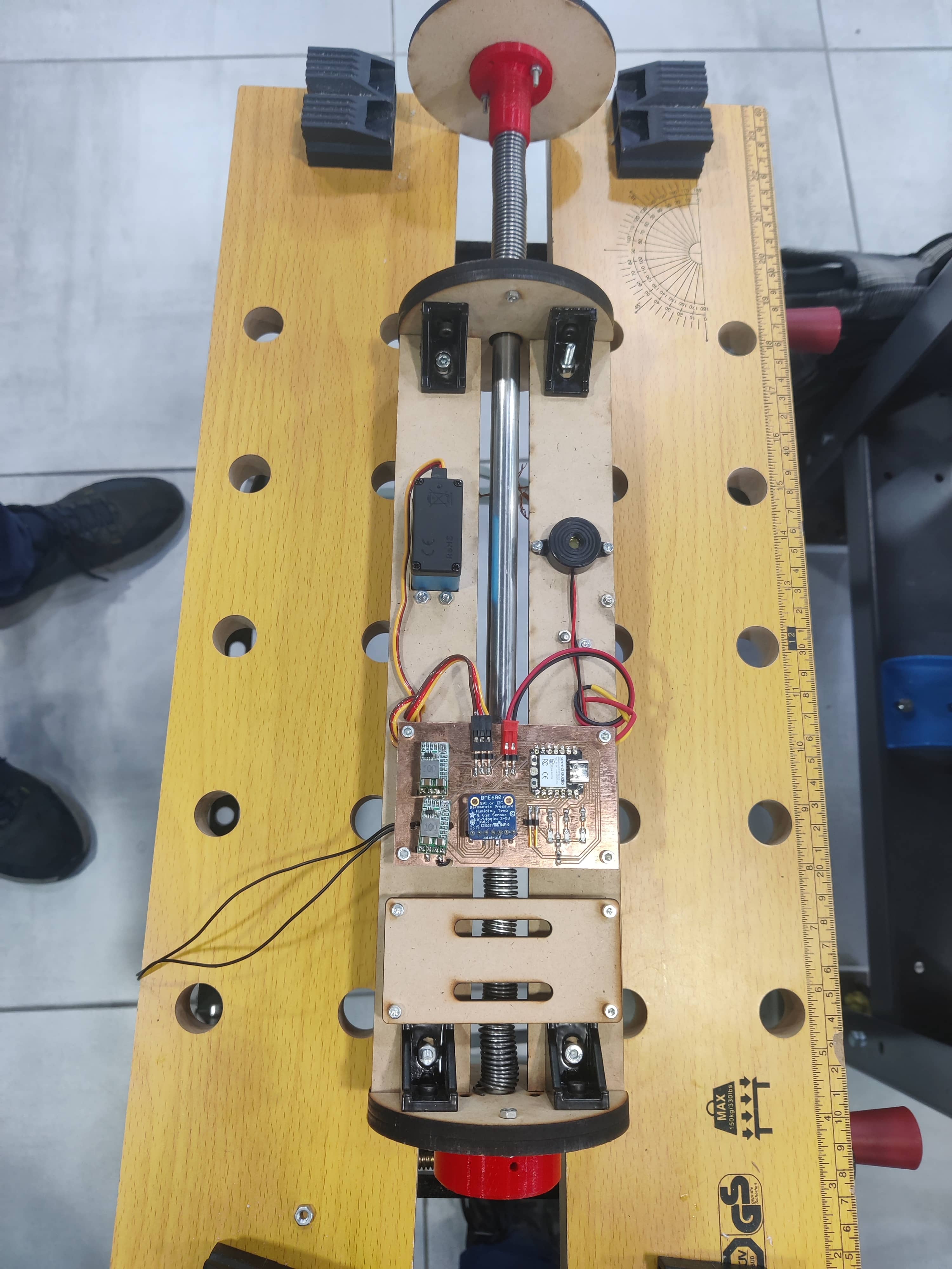
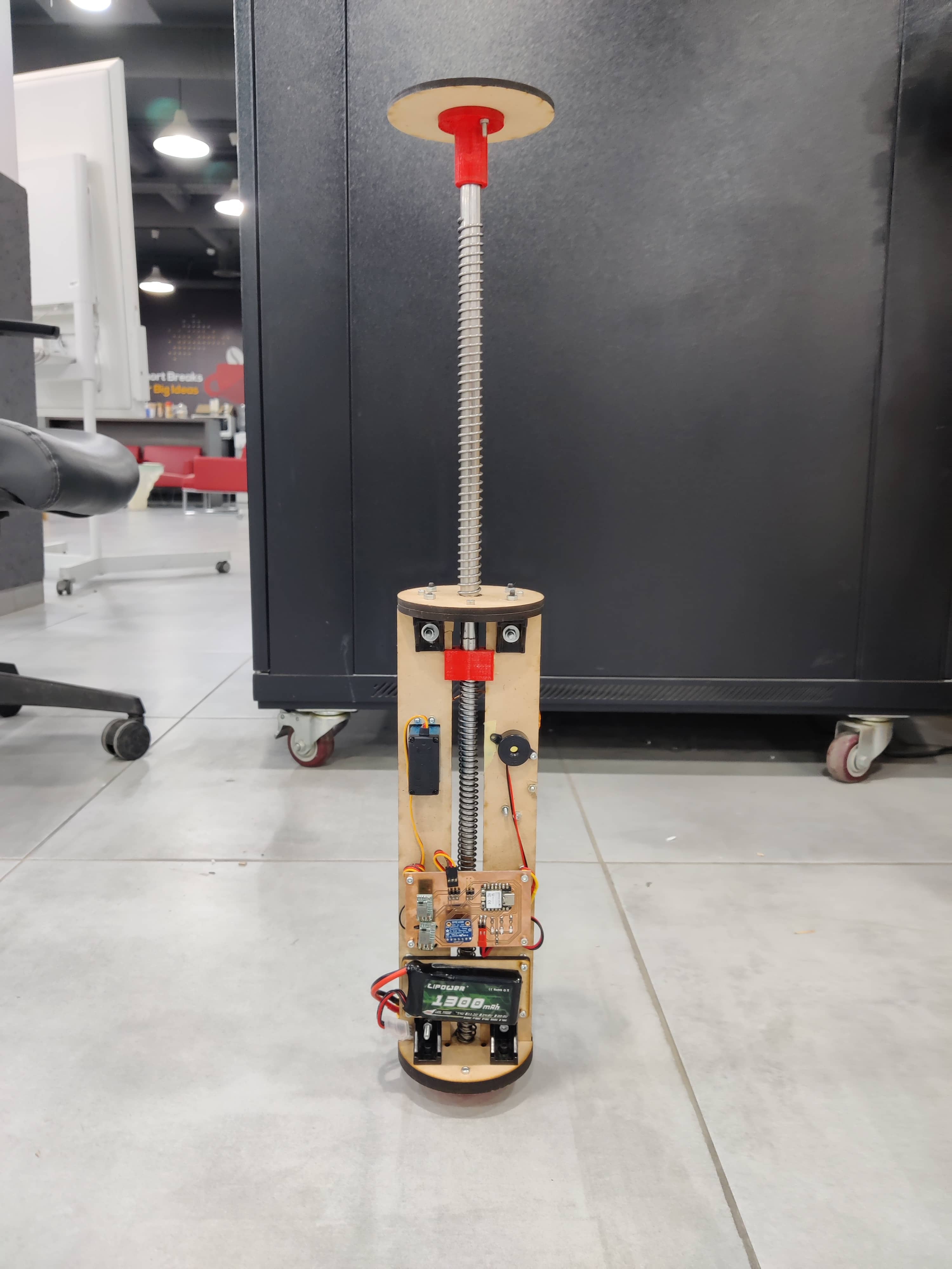
Electronics + Mechanical + Control System Integration
Week 17: Rail Button
Rail Button
Rail Button
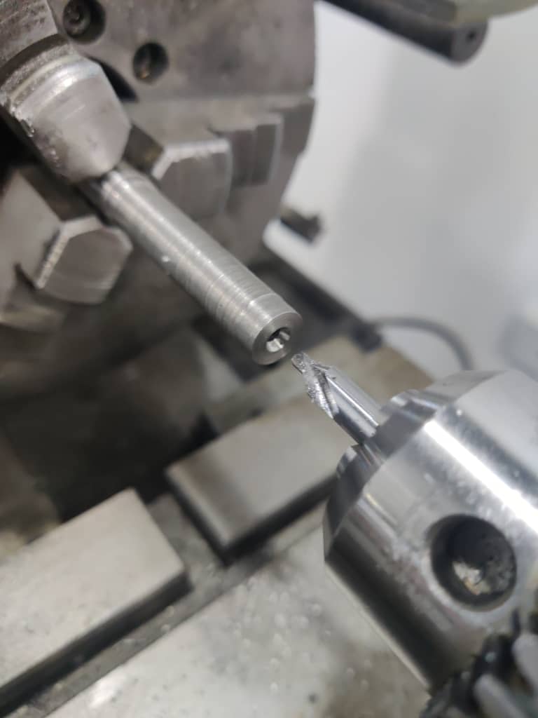
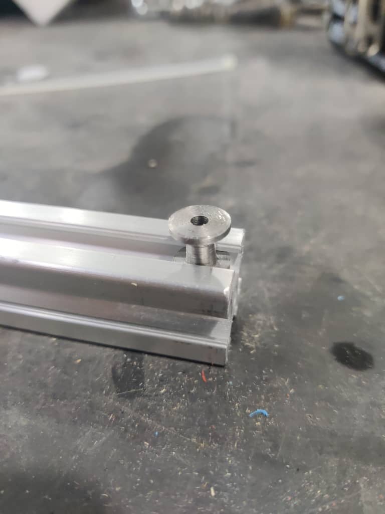
To ensure proper guidance of the rocket during launch, I needed to add a rail button — a small metal part designed to keep the rocket aligned with the launch rail. After researching available commercial options, I decided to machine a custom rail button in the lab.
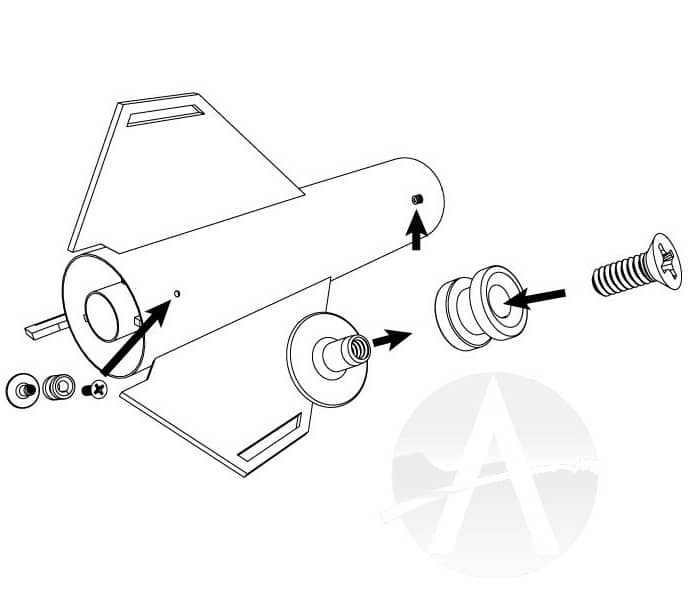
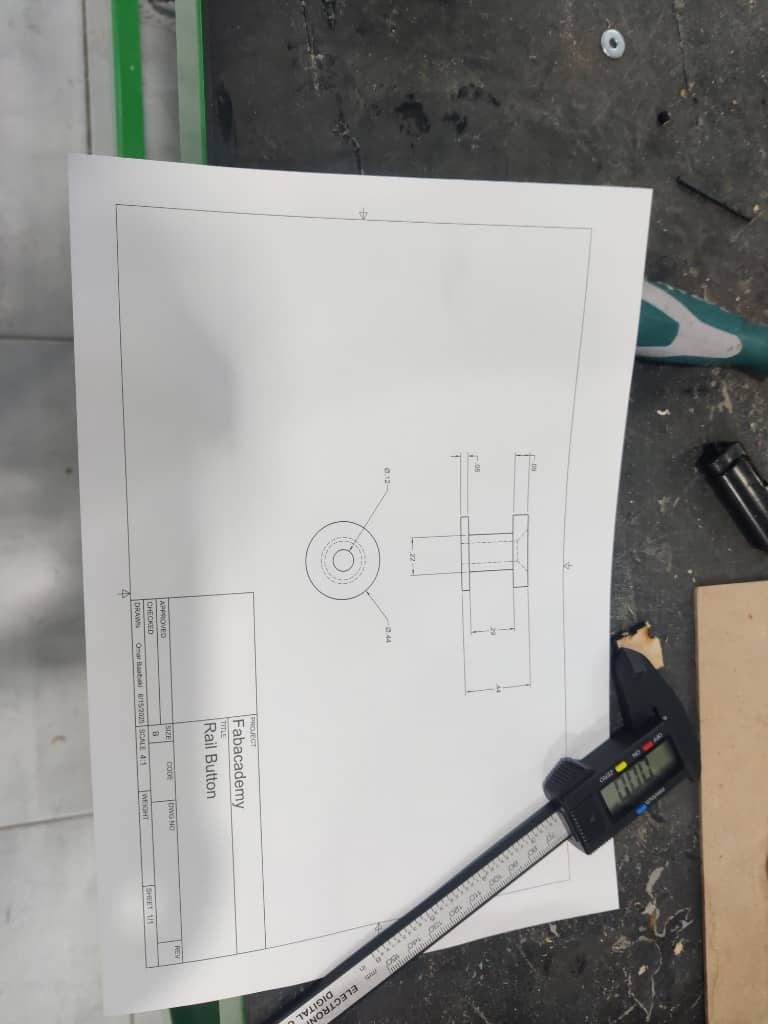
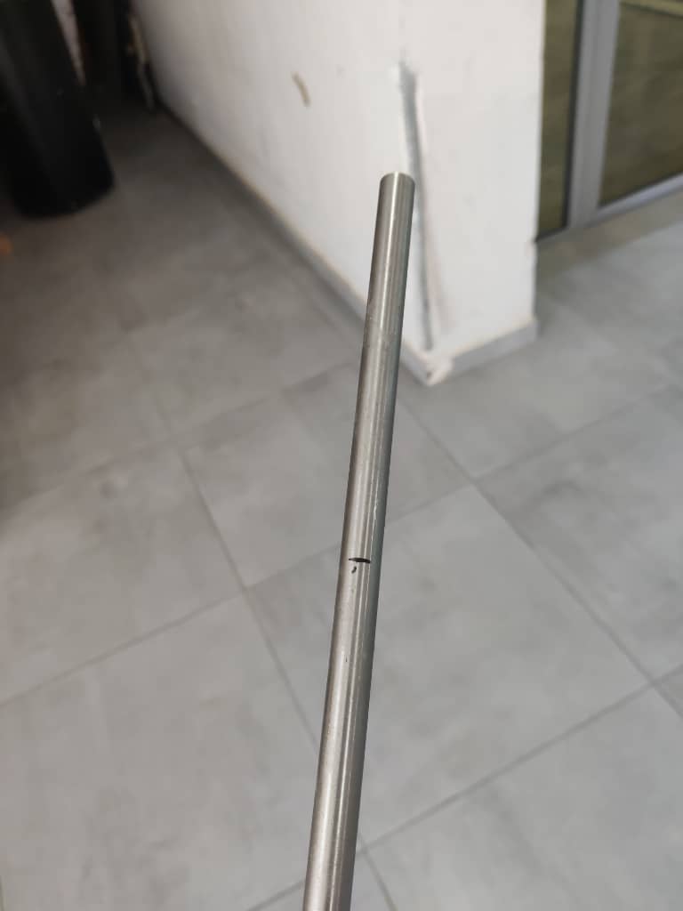
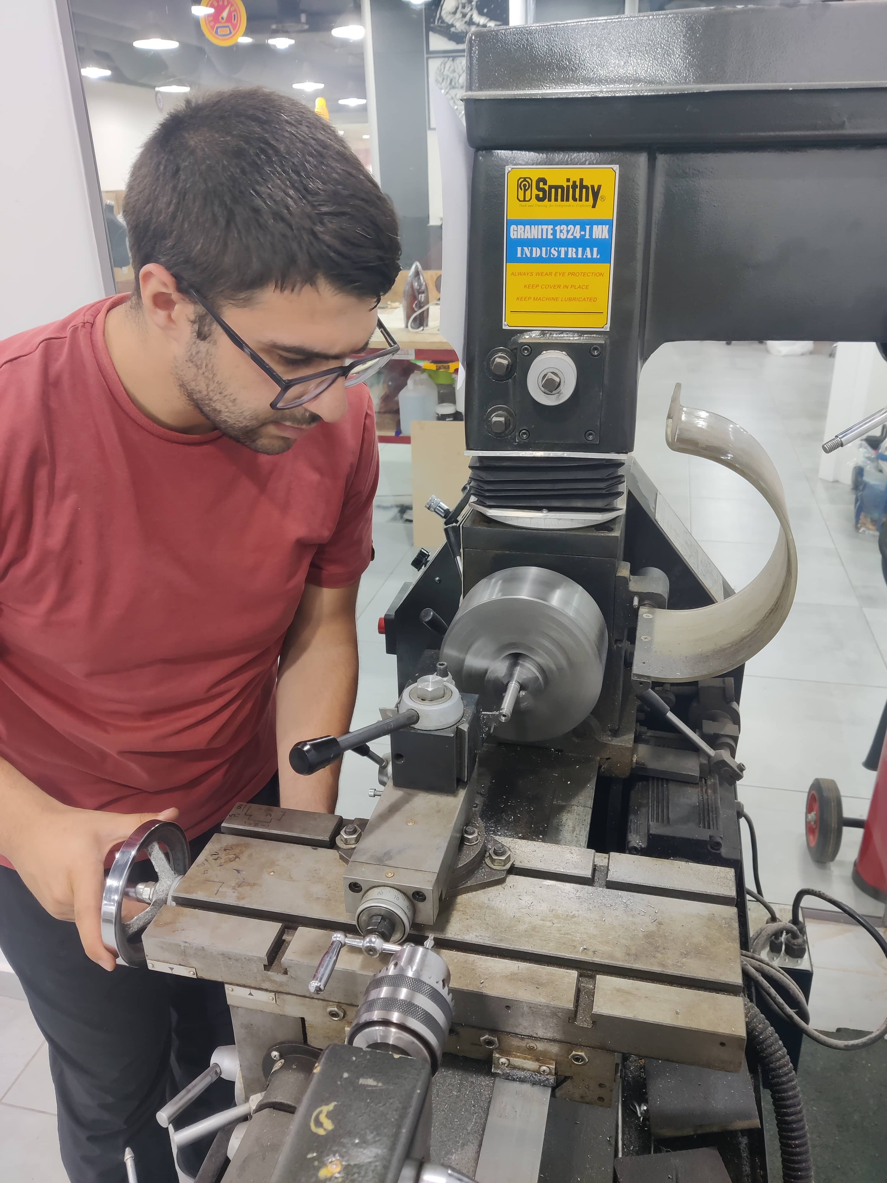
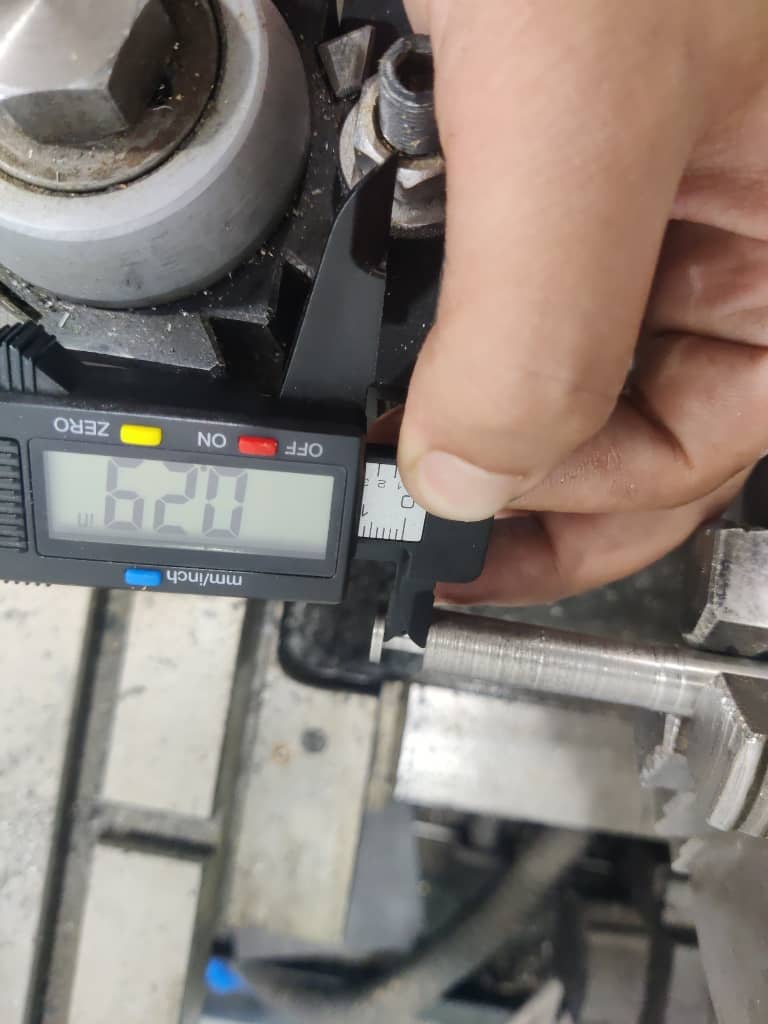
Using Fusion 360, I designed the part and printed a sketch to assist with the machining process. The chosen material was a 0.46-inch stainless steel tube. With support from a local instructor, I used the manual lathe to clean the surface, calibrate the setup, and begin shaping the part.
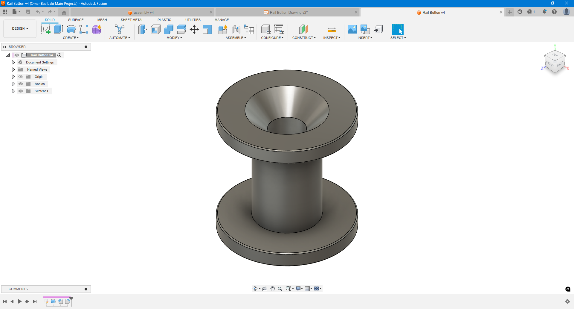
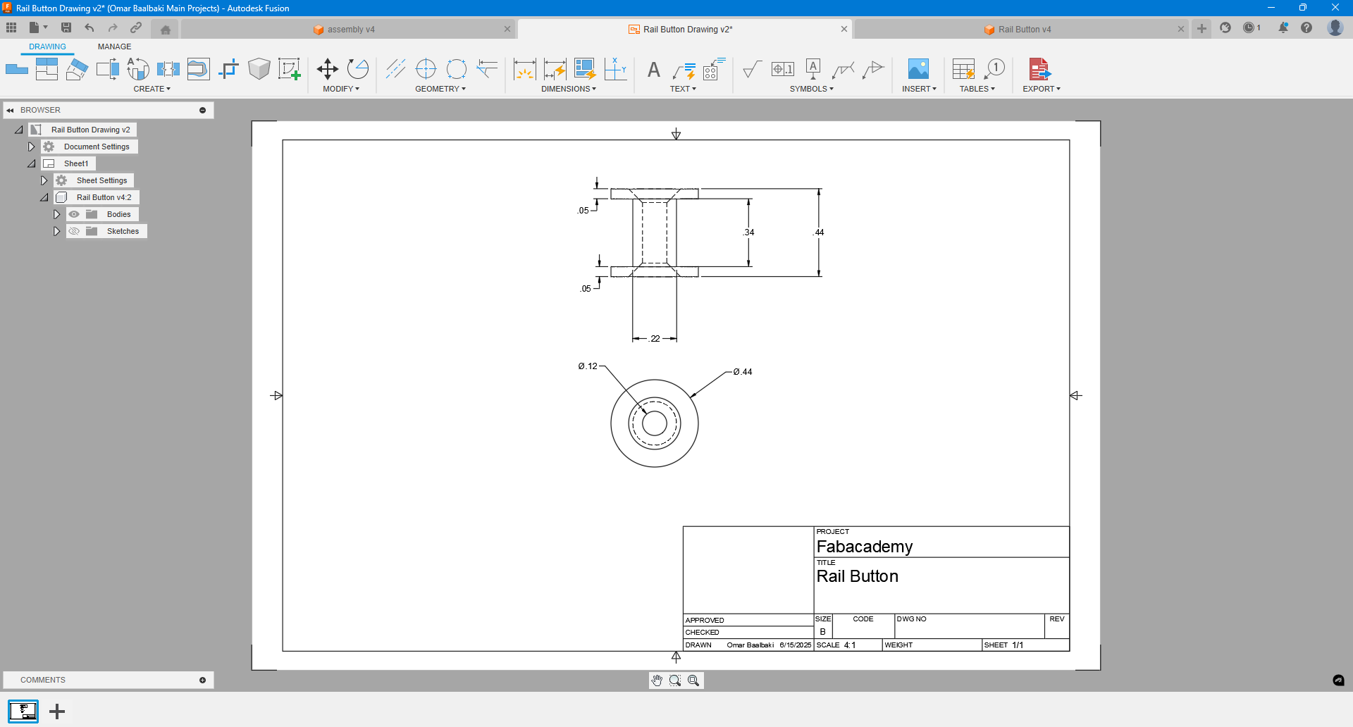
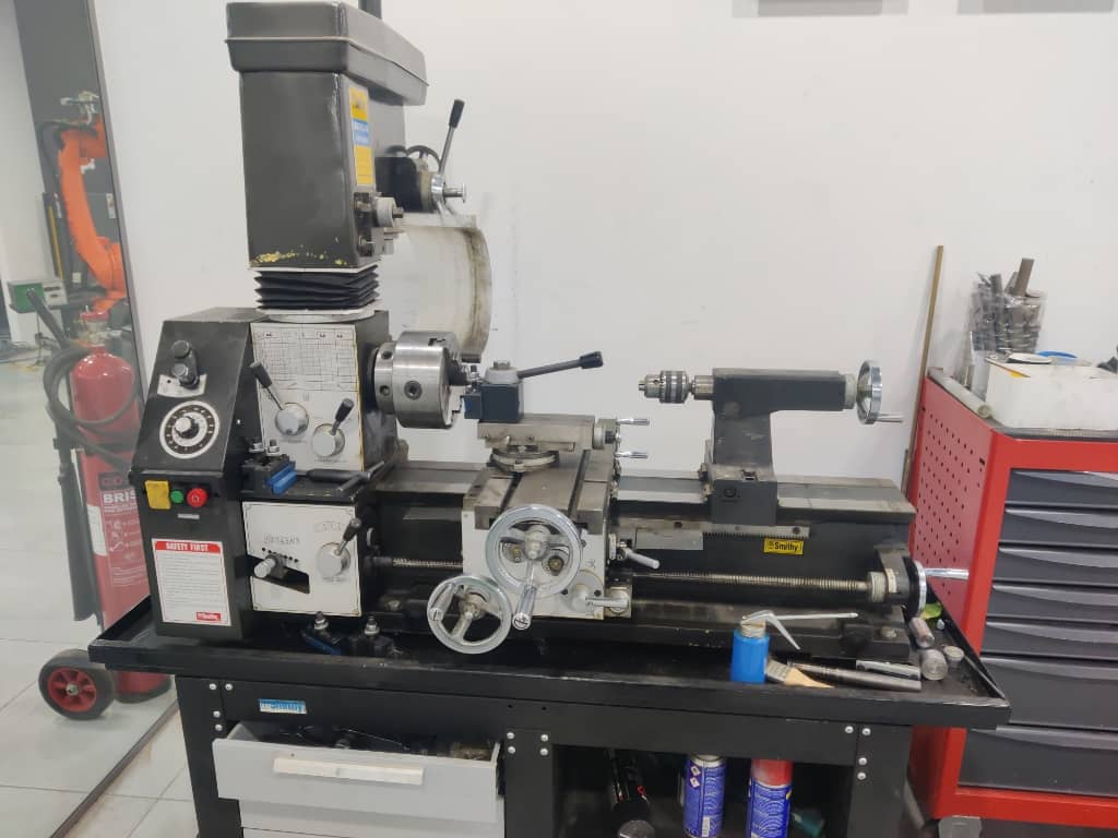
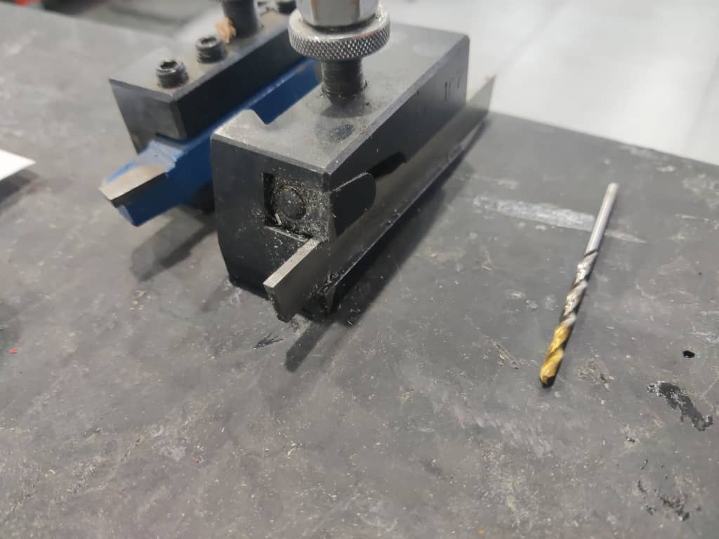
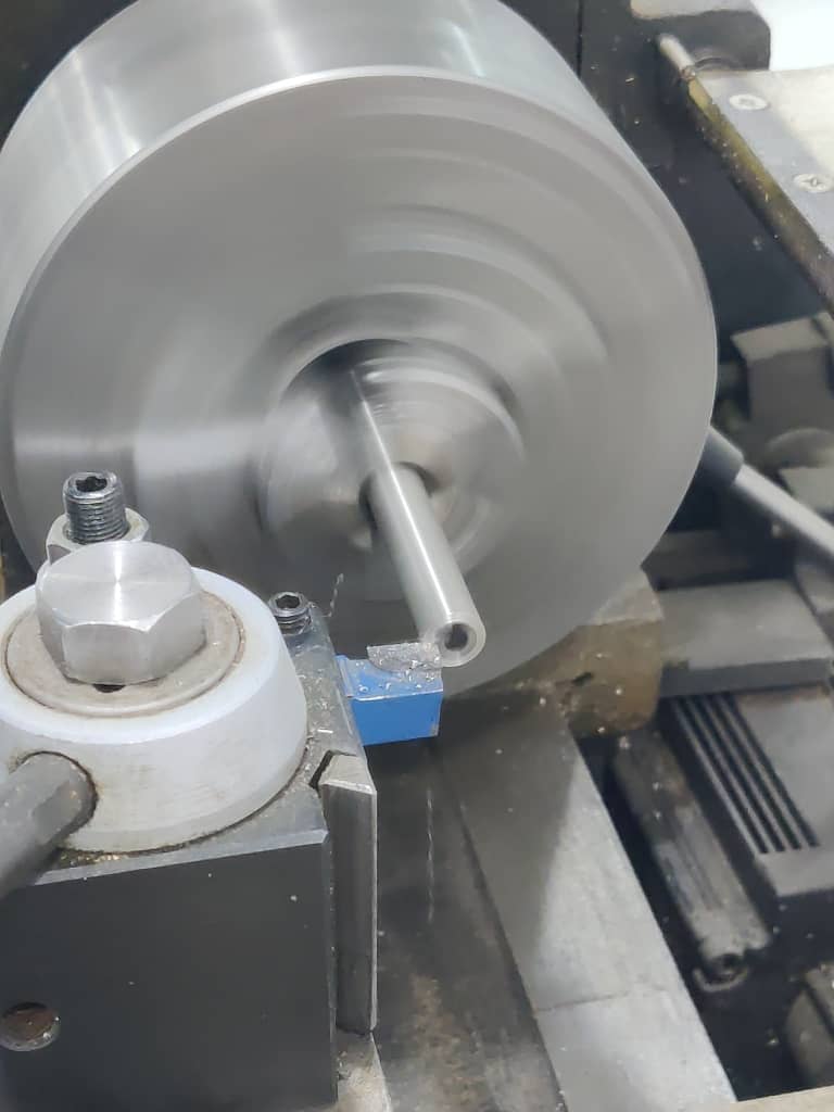
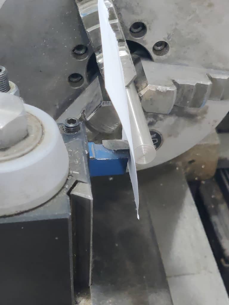
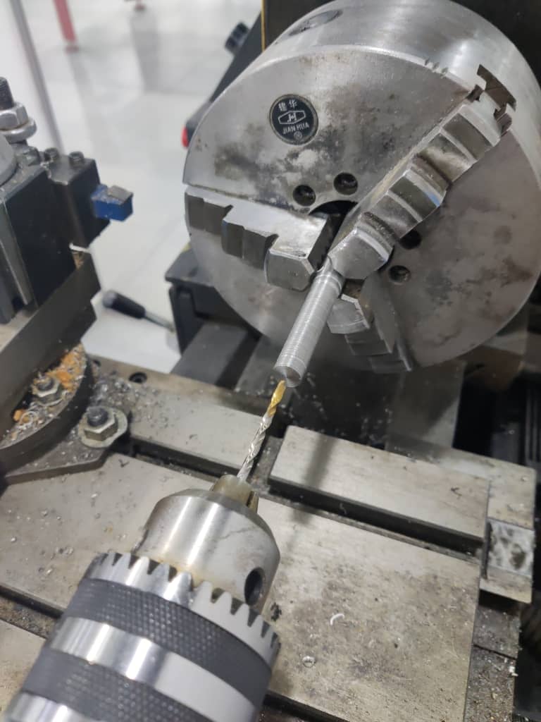
A key step was creating a chamfered hole for the screw, which would secure the rail button in place. This experience significantly deepened my understanding of manual machining and the importance of safety protocols and precision.
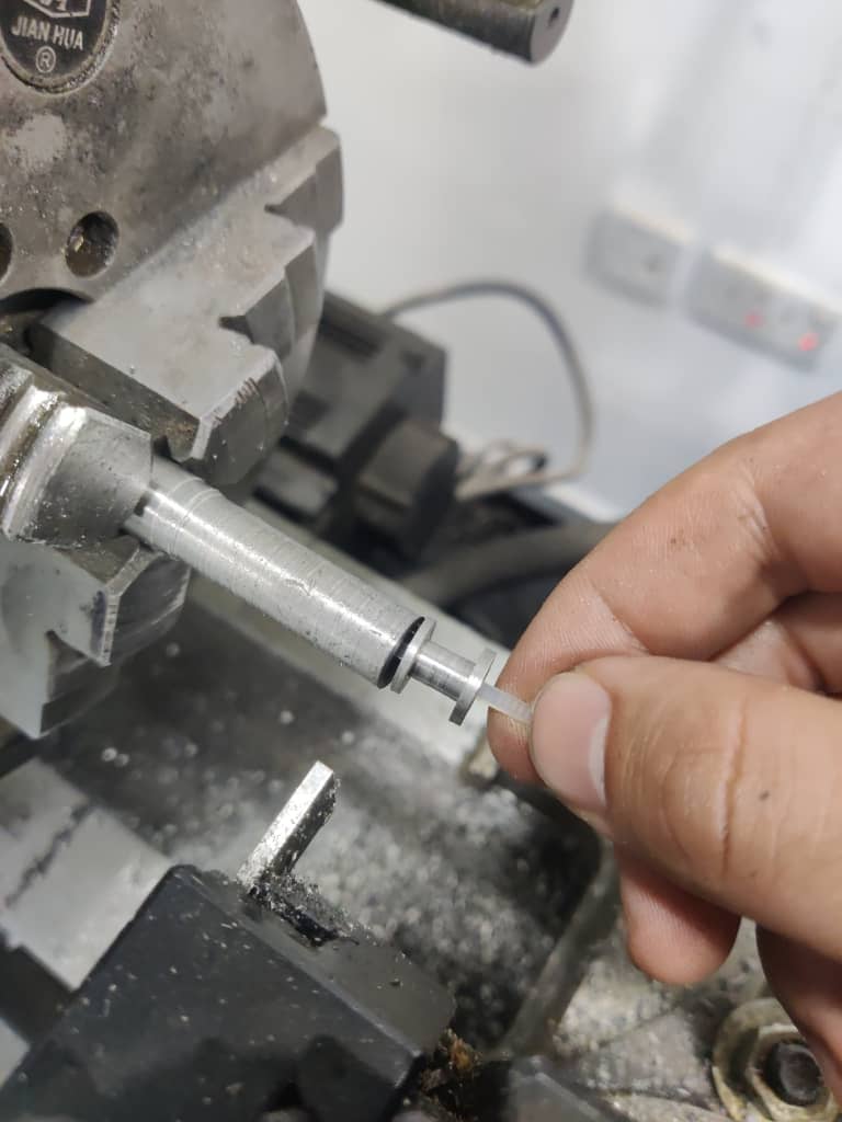
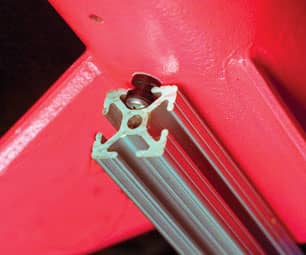
I later tested the machined rail button on a 20x20 aluminum profile, simulating a launch rail — and the result was successful. I plan to mount the button on the rocket once I finalize the launch pad design, ensuring everything aligns correctly.
Week 18: Applications and Implications
Applications and Implications
Applications and Implications
Week 19: Invention, intellectual property, and income
Invention, intellectual property, and income
Invention, intellectual property, and income
Invention, intellectual property, and income Page :